Contents
Introduction
This page tells you how to set up the axis compensation of your Ormerod 2 so that it can print accurately. You should have covered basic communication in the Commissioning section.
Ormerod supports both a USB interface, via the RepRap utility Pronterface, and an ethernet/web interface using a web browser. At the moment only the Google Chrome and Firefox web browsers are supported, though other browsers may well work too. Browser support will be expanded in future firmware releases.
Calibration
X, Y and Z axis calibration
The X, Y, Z and extruder axis calibration are expressed in ‘steps per mm’. This defines how may ‘steps’ the stepper motor has to move to move the axis 1mm. Because the X, Y and Z axes are fixed mechanical systems, this is already set for you in firmware, and should not need changing. When printing, if parts come out the wrong size, more likely you have backlash (mechanical movement) in the axes, or you are over- or under-extruding. If you change the steps per mm settings of X, Y or Z, you may fix one problem, but exacerbate another. The extruder axis is somewhat different, as it can be affected by the physical properties of the filament. It is covered in the next section.
More information on setting X, Y, and Z steps per mm
To check your settings, send ‘M92’ to the printer. It should respond (in the Pronterface log window, or the ‘Message Log’ tab of the web interface) with the current steps per mm setting for all axes, which will be something like:
For firmware version 0.78c and before, the setting for the X, Y axes show an integer with no decimal places; the exact steps per mm setting is actually 87.489:
Steps/mm: X: 87, Y: 87, Z: 4000, E: 420.000000:420.000000:420.000000:420.000000:420.000000
For firmware version 1.04 and later:
Steps/mm: X: 87.489, Y: 87.489, Z: 4000.0, E: 420.000:420.000:420.000:420.000:420.000
The extruder shows the steps per mm set to 420 steps per mm, for up to 5 extruders. See the next section about setting this more accurately.
For reference, we supply 200-steps-per-revolution stepper motors (1.8 degree per step), use 16x microstepping, MXL belt (2.032mm pitch), and 18-tooth pulleys on the X and Y axis. On the Z axis, the thread pitch of the M5 rod is 0.8mm. If you change any of these, you can use these numbers to work out the steps per mm, where:
Steps per mm for belt (X and Y axes)
= ( motor steps per revolution * microstepping ) / ( number of pulley teeth * belt tooth pitch )
= ( 200 * 16 ) / ( 18 * 2.032 )
= 87.489
Steps for leadscrew (Z axis)
= ( motor steps per revolution * microstepping ) / thread pitch
= (200 x 16) / 0.8
= 4000
You can also use the above information to calculate the steps per mm using Josef Prusa’s calculator here.
Set the steps per mm by sending:
M92 X87.489 Y87.489 Z4000 E420
You can do this just for one axis; the command doesn’t have to include all of them. To make this change permanent, add it to your config.g file on the SD card. The extruder value is set in the config.g already (‘M92 E420’); if you need to use different settings for the X, Y or Z, you can add it to this.
Extruder calibration
Load filament into the extruder
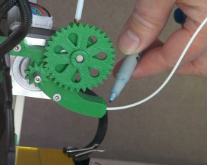
You can use Pronterface or the web interface. Select Motors Off (or send ‘M84’) so that you can turn the extruder mechanism by hand. Feed filament into the input of the filament drive, and wind the big gear until the filament is just visible in the PTFE Bowden tube. (Don’t pinch your finger in the gears…)
You can feed the filament all the way to the nozzle by hand by continuing to turn the large gear, if you wish. This can be useful, as you can feel if there is any resistance to movement, which you won’t feel if you command the extruder to push the filament through using its drive. Stop just before the filament disappears into the hot end.
You can also feed filament to the nozzle using the extruder drive.
The firmware has a built-in limit on extrusion if the temperature of the hot end is below 170C. Without this, if you try and extrude filament through the hot end when it is cold, the filament can’t move, so either the extruder stepper motor will skip, or the hobbed insert in the extruder drive will grind away at the stationary filament, and you’ll have to remove the filament, remove the extruder large gear, and clean the teeth of the hobbed insert, or it will slip on the filament when extruding.
First, make sure the hot end is ‘active’, either by clicking on ‘Heater 1’ in the web interface, or send:
T0
If the hot end is NOT enabled, you will get the message ‘attempting to extrude with no tool selected’ when you try and extrude.
As we want to feed filament up to the hot end, which is not heated up, we want to override this limit. To override this, send:
M302 P1
(This will revert the next time you reset or power off the Duet, or you can send ‘M302 P0’.)
You can feed filament at 800mm/m (web interface max speed is 240mm/m), at 100mm at a time, until the filament is near the nozzle. Then reduce the distance, and stop just before the filament disappears into the hot end.
Set the hot end temperature of the hot end to 200oC. When it gets to temperature feed the filament the last small distance to the nozzle. Make sure you slow down the filament as it enters the hot end, and extrude at 100mm/minute maximum. If you try and extrude too fast, there will not be sufficient time for the heater to melt the plastic, and the pressure required to extrude will increase until the filament starts slipping in the drive.
The firmware has a built-in limit on extrusion if the temperature of the hot end is below 170C. Without this, if you try and extrude filament through the hot end when it is cold, the filament can’t move, so either the extruder stepper motor will skip, or the hobbed insert in the extruder drive will grind away at the stationary filament, and you’ll have to remove the filament, remove the extruder large gear, and clean the teeth of the hobbed insert, or it will slip on the filament when extruding.
As we want to feed filament up to the hot end, which is not heated up, we want to override this limit. To override this, send:
M302
You can feed filament at 800mm/m (web interface max speed is 240mm/m), at 100mm at a time, until the filament is near the nozzle. Then reduce the distance, and stop just before the filament disappears into the hot end.
Set the hot end temperature of the hot end to 200oC. When it gets to temperature feed the filament the last small distance to the nozzle. Make sure you slow down the filament as it enters the hot end, and extrude at 100mm/minute maximum. If you try and extrude too fast, there will not be sufficient time for the heater to melt the plastic, and the pressure required to extrude will increase until the filament starts slipping in the drive.
So, before feeding the filament by Pronterface or the web interface, send:
M566 E50
In Pronterface, set the extrude distance in the box to the right of the ‘Extrude’ button, and the speed in the box to the right of the ‘Reverse’ button. These two boxes set the speed and distance, while the two ‘Extrude’ and ‘Reverse’ buttons set the direction. The web interface uses a simpler layout, with buttons for speed, direction and length.
You can feed filament at 800mm/m (web interface max speed is 240mm/m), at 100mm at a time, until the filament is near the nozzle. Then reduce the distance, and stop just before the filament disappears into the hot end.
Set the hot end temperature of the hot end to 200oC. When it gets to temperature feed the filament the last small distance to the nozzle. Make sure you slow down the filament as it enters the hot end, and extrude at 100mm/minute maximum. If you try and extrude too fast, there will not be sufficient time for the heater to melt the plastic, and the pressure required to extrude will increase until the filament starts slipping in the drive.
Once the filament has reached the nozzle, and you have tested some extrusion, send:
M566 E1200
to reset the extruder minimum speed for printing.
Removing filament from the extruder
If you need to remove or change the filament, with a little practice, you can get it to pull out the filament all the way to the nozzle’s tip. This can also pull out any contamination in the nozzle.
- Heat nozzle to operating temperature (200C for PLA).
- Extrude a little filament, like 10mm (if possible) by hand, with the motors off, or via the interface. Then set the temperature to 100C.
- Wait for the temperature to drop to 100C, then reverse filament until it comes out of the extruder drive (about 380mm). You can do this at 600mm/min, or by hand if you have disconnected the Bowden tube from the extruder.
- This should pull out the filament from the melt chamber, usually right down to the nozzle, along with any contamination.
- Feed new filament in, as per the instructions in the section above.
Set the extruder axis steps per mm
For initial setup, the extruder steps per mm are set in config.g to a standard setting of 420 steps per mm. This should be sufficient to get you printing the test gcode files included in the SD Image. To get the best quality prints, you may need to make fine adjustments to the filament feed to make it as accurate as possible.
More information on setting extruder steps per mm
You can use Pronterface or the web interface for setting the extruder steps per mm. If you use the web interface, click on the ‘Message log’ tab, to see the firmware response to commands.
Select Motors Off, so that you can turn the extruder mechanism by hand. Feed filament into the input of the filament drive, and wind the big gear until the filament is just visible in the PTFE Bowden tube. (Don’t pinch your finger in the gears…) Then use a felt-tipped pen carefully to mark the filament just where it enters the mechanism.
Now tell Ormerod 2 to feed 100mm of filament. Mark the filament again.
Reverse the filament by 110 mm, so you can see both marks. Using a ruler carefully measure between them. The measurement probably won’t be exactly 100mm. Suppose it is 97mm.
Now send an M92 command. The result in the USB interface window will be something like:
Steps/mm: X: 87.489, Y: 87.489, Z: 4000.0, E: 420.0:420.0:420.0:420.0:420.0
These numbers are the number of pulses sent to each stepper motor to drive it 1mm. There are five extruder values because the firmware supports up to five extruder drives.
Because you only got 97mm and you wanted 100mm, the E420 needs to change to 420x(100/97), which is to say 433. Do that calculation for the length you measured, then add a line saying
M92 E433
but with your number in place of the 433 to your config.g file. M92 with no arguments reports the values; if you give it a value, it sets it.
(You only need to specify one E value – that will set all five values to that one. In multiple-drive machines you can set them individually thus: M92 E433:427:440:425:429 )
Now your Ormerod will extrude precisely the right amount of filament when it’s printing.
Level the bed manually
You should only need to do this once when you first build your machine. Though you may need to repeat this if you drop the machine (try to avoid that…) or take it on a bumpy journey. You can then use the automatic bed plane compensation to level the bed due to day-to-day movement.
It would be very difficult to build a machine that was perfectly square and needed no compensation. But it is easy to build one that is approximately square and then to use the power of the on-board computer to compensate for slight inaccuracies. The Ormerod 2 should be fairly square anyway, but getting the bed plane reasonably flat before doing the Bed Plane Compensation described below will improve the results.
For this it is useful to have a drill bit of known diameter – say 3mm. You are not going to make any holes. But you can use the cylindrical drill shank as a 3mm reference.
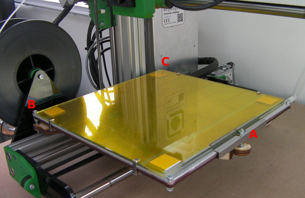
The main adjusting screws are A B C in the picture. You will remember that you put nyloc nuts on the bed screws to allow you to adjust the bed. There are conventional nuts opposing these – slacken them off. It is also useful to know that one full turn of an M3 nut on its screw moves by 0.5mm. You can use a felt-tipped pen to mark one face on the nylock nuts so you can tell how many times you turn them.
Home the X, Y axes. Move the nozzle over point B. We haven’t set up the Z axis homing yet (next section) so move the Z down, until the drill shank will just roll under the nozzle.
Move the Y axis to about Y = 190 (at C). Roll the drill under the nozzle. You will probably find that the bed is either too high or too low. Adjust the screw in that corner so that the drill just rolls under the nozzle. If you have to adjust too far, it may be better to go back and do some adjustment at the Y = 0 end. The important thing is not to achieve any particular height – it is to get both ends the same. Take care when making the adjustments that you don’t cause the ends of the screws to scrape on the aluminium extrusion beneath them.
Now move to X=190 Y = 100 and adjust the height over the screw in the middle of the far edge – the edge that sticks out, screw A.
Tighten the nuts to clamp the bed firmly and run the checks above again to make sure nothing has moved when you did the tightening. You may have to slacken a nut or two and make a small adjustment again.
The bed will now be much more accurately flat.
Setting the Z Probe
Quick method
If it’s the first time you are setting the Z Probe (proximity probe), read the next section ‘Setting the Z Probe’ first, for a full explanation.
- Send M561 then M556 S100 X0 Y0 Z0. This resets any bed plane and orthogonal axis compensation.
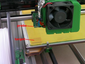
- Move the X axis so that the proximity probe is over the bed target closest to X0 Y0. This is usually around X40 Y0. If the X and Y axes are homed, you can use ‘G1 X40 Y0’ to go there.
- Move the Z axis down so the nozzle just touches the bed; use a piece of paper, move Z down 0.1mm at a time, until it traps the paper. Then move it down 0.1mm more.
- Send G92 Z0. This sets the current Z position to 0, for reference.
- Move the Z axis up 2mm. Send G31. The response will most likely be less than 600.
- Move the Z axis up 0.1mm. Send G31.
- Repeat the above until G31 reports a value of around 600, +/-20
- Send M114, and note the Z height.
- Send G31 Z[zzz] P[ppp], where [zzz] is the height of Z from the M114 command, and [ppp] is the value reported by the last G31 command
- An EXAMPLE might be: G31 Z2.5 P598
- Home Z to test, and adjust as necessary.
- Copy the G31 Z[zzz] P[ppp] command you have derived into the config.g file on the SD card.
The sensor works best in the range around 600. At this distance the nozzle can be between 1.5mm and 4mm from the bed, depending on your printer. We don’t set the sensor at the point the nozzle is touching the bed – the reading is too high and inaccurate.
Setting the Z Probe – first time
The proximity sensor (also known as the Z probe) uses an infra-red sensor to detect the paper targets that you put under the Kapton tape on the bed glass.
Plug both the USB and ethernet cables in and turn on the power.
Now a useful thing: you can use both the USB and ethernet interfaces at the same time – the RepRap Firmware in the Duet controller will sort everything out for you. Open the Arduino IDE and go to Tools->Port and select the USB port for your Ormerod 2. Then go to Tools->Serial Monitor. Make sure the speed is set to 115200 (bottom right) and that Newline is selected (next to the speed). Now type an M105 G-Code command to your Ormerod 2 in the Send bar and send it:
serial: M105
ok T:16.3 B:18.9
Ormerod 2 is saying it got a command on its serial (i.e. USB) interface, and is reporting its temperatures to you. You are talking directly to the USB interface, something that is normally mediated by Pronterface. You can actually do the whole of this section just by typing commands at this interface. but things will be quicker if you also use the ethernet interface at the same time. Open a browser and connect to the IP address you set for your Ormerod 2 in the Commissioning Section.
(If the web interface is not working, you can debug it by using the Serial Monitor to send M111 S9 – debug HTTP requests.)
On the web control page lift the Ormerod’s Z axis by +10mm to make sure the nozzle is well clear of the bed, then select Home X and Home Y. Those two axes should zero themselves.
Now use the controls to move the Z probe over the paper target in the bed corner. (X = 40, Y = 0) should be about right.
Send the command M558 P2. This activates the Z probe. This should already be in your config.g file, but make sure it loads on startup (see the section in the Commissioning instructions).
Make sure the tag is well under the probe – you don’t want the probe near its edge.
Now move the Z axis down so that the nozzle is a tiny bit above the bed and you can just see light between the two. Take care – you don’t want to crash the nozzle into the bed. When you get near, move in 0.1mm increments.
Send a G92 Z0 command. You should see the Z position on the Control page go to 0.0. G92 tells the RepRap Firmware that an axis is at whatever position you specify. As the nozzle is almost touching the bed, we want this to be Z = 0.
Next send a G31 command. This fires the Z probe and reports the measurement it makes in the Serial Monitor window. The measurement should be about 950 or so.
(What’s going on? The Z probe works by reflected IR light. The closer it gets to the paper target the more light is reflected, and this sends back a bigger voltage to the Duet controller, which converts the voltage into a number. The biggest possible voltage is 3.3 volts, which the Duet would convert to 1023 = 210 – 1. So the 950 means “pretty close”.)
Now. It is not a good idea to zero the Z axis by driving it down and looking for this value for two reasons:
- The probe is not very accurate or sensitive at the very top end of its range, and
- It gives us no room for error – we might crash the bed.
So, raise the Z axis in small increments and send a G31 after each movement. As you start, you will see almost no change (not very accurate or sensitive at the top of its range, remember?), but then the readings will start to drop. Stop when they are around 600. Suppose the value is 590. Look at the Z position box. Z will probably be between 2 and 3mm off the bed – say it’s 2.3mm.
Now send G31 Z2.3 P590
This use of G31 sets values, rather than reporting them to you. It tells the Duet that a reading of 590 corresponds to Z = 2.3 mm off the bed.
Now when you select Home Z, Z will drop until the Duet detects a probe reading of 590. It will then lower by a further 2.3mm, and you will be at Z = 0. Try it: raise Z to about 10mm, then select Home Z. Ormerod 2 will home its Z axis.
This is all very well, but you don’t want to go through this rigmarole every time you turn on the machine. So put the G31 Z2.3 P590 (with your numbers, obviously) in the Ormerod’s config.g file. That will set these values every time you reset the machine. See here for how to edit the config.g file.
As mentioned above, the position X=40, Y=0 should be about right for the IR probe to be above the paper target. But if your position is significantly different you will also want to record that permanently so that your RepRap always homes its Z axis in the right X,Y position. The axes are all homed by macros. These are little G Code files stored in the sys folder on the SD card, and are described here. There is one called homez.g. As supplied it looks like this (with comments for explanation):
G91 ; set movements relative
G1 Z5 F200 ; move upwards 5mm at 200 mm/min to make sure we don't hit anything
G90 ; set movements absolute
G1 X40 Y0 ; Move to the X, Y point at which to probe the bed over the paper
G30 ; Move down until the probe is triggered (i.e. move down until the IR voltage is 590, which automatically sets Z = 2.3mm).
G1 Z0 F200 ; Move down to Z=0 (i.e. move down the last 2.3mm)
If your paper is in a different place, change the G1 X40 Y0 line to the appropriate X and Y coordinates.
There is also a file called homeall.g. This is used to home all three axes at once (this is more efficient than calling the separate macros for each axis in turn). Open that and change the G1 X55 Y0 to your paper coordinates too.
Compensation
Bed Plane Compensation
Ormerod 2 allows you to compensate for the fact that the plane of its printing surface may not be exactly at right-angles to its Z direction. This section tells you how to implement this.
Fully automatic bed plane compensation is a very easy process. It uses the IR Z probe to probe the bed in four places automatically.
Now record the points at which you want automatic probing to take place. You put them in the file bed.g in the sys folder. Here is that file with the lines you need to change marked ***:
M561                  ; Zero any previous bed compensation
 G1 Z10 F200          ; Move 10mm off the bed
 G1 X55 Y0 F2000      ; *** First probe point
 G30 P0 Z-100000      ; Probe the bed
 G1 Z10 F200          ; Move back up
 G1 X55 Y175 F2000    ; *** Second probe point
 G30 P1 Z-100000      ; Probe the bed
 G1 Z10 F200          ; Move back up
 G1 X205 Y175 F2000   ; *** Third probe point
 G30 P2 Z-100000      ; Probe the bed
 G1 Z10 F200          ; Move back up
 G1 X205 Y0 F2000     ; *** Fourth probe point
 G30 P3 S Z-100000    ; Probe the bed and use the four measured points to set the bed equation
 G4 P1500             ; Pause to give the web interface time to report the points
 G1 Z10               ; Move back up
Make sure you set them in clockwise order round the rectangle, starting near the origin.
Now sending a G32 command will run bed.g, causing Ormerod 2 to probe all four points and set the bed compensation automatically.
Now record the points at which you want automatic probing to take place. You can either put these in a short G-code file that you run, or add them to config.g.
M557 P0 X60 Y0
M557 P1 X60 Y180
M557 P2 X220 Y180
M557 P3 X220 Y0
Make sure you set them in clockwise order round the rectangle, starting near the origin.
Now sending a G32 command will cause Ormerod 2 to probe all four points and set the bed compensation automatically.
Orthogonal Axis Compensation
Before doing the compensation described in this section, first do the Bed Plane Compensation described above. Orthogonal Axis Compensation depends on having the bed plane right.
This compensation is not intended to avoid all the effort in getting the axes at right angles. During construction you should have used a square on the Y axis to set the vertical Z pillar at right angles to it.
Now skip to the Printing Instructions. They tell you how to do your first print, which you will need to set the orthogonal axis compensation. Then come back and do the rest of this section….
Setting the compensation from the printed test parts
Ormerod 2 allows you to compensate for the fact that its X, Y, and Z axes may not have been assembled at perfect right angles. This section tells you how to implement this.

