
Goal
By the end of this stage, your machine will look like this:

Tools
- Wire cutters
- Soldering iron
- Allen key
Heated bed assembly
| Hardware | Quantity |  There should be 3 more M3 nuts and 3 more M3 washers in this picture |
| Heated bed PCB | 1 | |
| Aluminium plate | 1 | |
| MDF insulator | 1 | |
| Bed springs | 3 | |
| 3-way screw connector | 1 | |
| 4-way pin header | 1 | |
| short wire (e.g. clipped resistor lead) | 20mm | |
| M3x30mm screw | 3 | |
| M3x8mm screw | 4 | |
| M3 nylock nut | 3 | |
| M3 nut | 6 | |
| M3 washer | 10 |

Start by soldering the connectors in place. The wire holes on the screw connector face outwards.
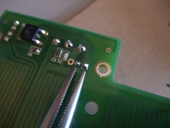
Use a very short length of wire to make a jumper between the left two holes beside the 3-way screw connector. Be particularly careful when soldering the large connector. You need to ensure that there is no dry joint and that there is a reasonable, although no excessive, amount of solder. This connector has to take quite a high current.

Assemble the heatbed components. From the top down in the picture they go: MDF insulator (lasercut lettering upwards, so you can see it), PCB (circuit side down, towards aluminum bed-plate), Aluminium plate. The notch in the MDF aligns with the Y axis motor mount, so that the bed can be as low as possible, but can still move the full distance in Y.

The aluminium plate has a recess in the centre to accommodate the tiny surface mount thermistor in the middle of the PCB.

Take care when sandwiching the parts together that the edge of the recess does not hit the thermistor – you don’t want to knock it off… NOTE : The thermistor should be electrically insulated from the Aluminium plate. This can be achieved using a small piece of Kapton tape over the thermistor.

Put washers under the heads of the four short M3 screws and screw them through the stack to hold it together. Don’t do the screws up so tight that they project through the aluminium plate. The ends of the screws need to be just below the plane of the top of the plate. If they project, put extra washers under their heads.

Fitting the bed to the frame

On the bed adjusters, one M3 nut holds the spring under pressure, the other fits into the captive nut hole in Y sled. You can tighten the M3 nut that holds the spring up to the shank of the bolt (the unthreaded part); this will put the spring under load, and hold the bed firmly. Use the screws to attach the heated bed to the machine. The lower M3 nut sits in the hex hole in the Y sled. Screw the screws into the nylock nuts until the bed is secure and roughly level. Tighten them gently against the sled by unscrewing them without holding the nyloc; this pulls the M3 nut on top into the hex trap, and against the nyloc.
To level the bed accurately later, you will slacken those nuts, adjust the screws in the nylocks, then tighten the nuts again.
You should be able to push the bed down easily with a finger, and it should spring smartly back up again to rest under the screw heads.
Carefully run the Y-axis back and forth by turning the toothed pulley on the Y motor by hand. Make sure that nothing hits anything.