
Goal
By the end of this stage you will have finished all the mechanical construction! All that will remain is electrical wiring and commissioning.
Your hot end will be fitted to your Mendel like this:

The above picture shows the hot end mounted on the back-left of the X carriage (photo is taken from the back of the machine). You can mount the hot end in any available slot. If you are building a Tricolour, our standard slot for the first extruder is front-left.
Tools
You will need the following tools:
- Allen key
- Small screwdriver
- Pliers
- Adjustable spanner
- Heat sources (small blowtorch plus hairdryer/soldering-iron)
- Bench vice
Parts
 |
|
| Hardware | Quantity |
| Heater block and nozzle | |
| 100K thermistor | 1 |
| PTFE (Clear) Heatshrink sleeve | 1 |
| Aluminium heater block | 1 |
| Crimps | 2 |
| Polyolefin (Black) Heatshrink sleeve | 2 x 20mm |
| Stainless steel one-piece nozzle | 1 |
| 2mm (ID) x 3mm (OD) PTFE tubing | 20mm |
| Bowden cable | |
| PTFE tube | 1 |
| Slotted brass union | 1 |
| Threaded brass union | 1 |
| Tongue (printed) | 1 |
| Cooling system | |
| Aluminium cooling block | 1 |
| Fan and heatsink | 1 |
| M3 x 25mm screws | 2 |
| Cable ties | 1 |
| Assembly | |
| Brass tapered nut | 1 |
| Heater cartridge | 1 |
| PTFE spacer or 2 X double coil spring washers | 1 |
| M3 x 16mm screws | 2 |
| Wiring | |
| 10cm high current wires (excess from stepper motors) | 2 (not red or black) |
| Polyolefin (Black) Heatshrink sleeve | 6 x 15mm |
| Pin header | 2 |
| 8-way ribbon cable | 1.2m |
| Crimps | 2 |
HOT END BUILD NOTES
- If you have a brass nozzle and separate stainless barrel or a power resistor instead of a heater cartridge like the pictures below, you will need to refer to the archived instructions [here], page 78.


- The thermistor heatshrink is easy to confuse with the PTFE for the extruder Bowden tube, or the PTFE for the nozzle. The heatshrink is the shorter one made from thinner material.
- There are several stages in this construction where you have to trim pieces of PTFE. It is essential to clear any swarf created away and not to let it get into the extruder. PTFE swarf will travel to the nozzle and block it if it is allowed to contaminate the device.
- Please note, in newer machines double coil spring washers shown on the left below have replaced the PTFE spacer shown on the right for extra height adjustment when using multiple heads. These often lock together during transport. Double check your spring washers are separated

The hot part of the hot end
The heater block
First fit the thermistor. For this step, you will need the axial thermistor, length of PTFE (clear) heatshrink and the heater block.

Cut the PTFE heatshrink such that when slid over the thermistor, approximately 5mm of the leads are bare at each end. With the PTFE heatshrink in position, use a heat source to shrink the PTFE around the thermistor bead and leads. PTFE heatshrink requires temperatures in excess of 300C to shrink. A naked flame will do for this. Keep the flame moving whilst shrinking the PTFE.
![]()
Take the sheathed thermistor, and slide one lead into the small hole in the heater block. With the thermistor bead up to the side of the heater block, the PTFE heatshrink should protrude form the other side of the block. Grasp the PTFE heatshrink with some pliers, and pull the thermistor through until the bead is roughly in the centre of the heater block.

Set the heater block aside for use in a minute.
The nozzle
It is essential that the nozzle is free from contamination before assembly.
Metal swarf from manufacturing may still be inside it. The best thing to do is to rinse it in a degreaser, use a rolled up piece of tissue to pull out any large parts, rinse in Acetone, and blow air through from the nozzle end. Check you can see daylight all the way through it.
NOTE: From 1/7/2014, we ship all hot end nozzles with the PTFE tube pre-cut, and inserted into the nozzle; it should look like the image below.

Older kits are supplied with the PTFE tube separate from the nozzle. Follow the instructions below if you have received the PTFE tube uncut, or need to recut the tube. We will need a short length (about 10mm) of 3mm diameter PTFE tube to line the cold end of the one-piece nozzle.

Using a sharp blade, cut one end of the PTFE liner. Try to make the cut as square to the axis of the tube as possible. Push this into the counter-bore at the cold end of the one-piece nozzle. Again using a sharp blade, cut the PTFE liner flush with the cold end of the one-piece nozzle.
Take a 5mm drill and gently twist it against the end of the PTFE that you have just created to dish it slightly. Make sure you clear all swarf away. Now set the one-piece nozzle to one side.
The Bowden tube
Use a sharp blade to trim a few millimetres off the end of the tube at right angles to get a clean square end.
Screw the tube into one of the brass unions. Look in the other end (a magnifying glass is useful) to see when it gets to the end of the internal thread, then stop. If you have trouble starting the threading, make a small cone on the end with a pencil sharpener. Don’t cut too far – PTFE is very soft. The cone makes it easier to start the thread.
Screwing the tube in will have reduced its internal diameter slightly. Gently twist a 2mm drill by hand in the end of the brass to thin the tube where it is inside the screw thread. If you have a small hand-chuck this is made easier.

Repeat the process with the other brass union, putting it on the other end of the tube.

Push a length of 1.75mm build filament down the tube from the other end to clear out any PTFE swarf – any left behind will block your nozzle! Make sure the filament runs freely down the tube and comes out of the far end without impediment.
The cooling system
Now you will assemble the cooling system.

Some heatsinks come with a sticky backing which you will need to peel off. This can be quite tough – you may need to pull with pliers.
Take the heatsink and the cable tie. You’ll notice that one edge of the heatsink has two holes for mounting. Insert the cable tie around one of the fins on the opposite end of the heatsink. This will be used to assist with wiring later.

You can put a little heatsink grease on the aluminium cooling block if you like. Attach it to the fan with the two M3x25mm capscrews. Feed the screws in through the fan, through the heatsink and into the cooling block.

Now screw the brass bowden end piece (with the PTFE bowden tube screwed into it), into the Aluminium heatsink block (the long thin one with five holes in it).

Once fully screwed in, screw the free end of the barrel into the M5 hole in the Aluminium heatsink block until it meets the brass piece. Now unscrew the brass piece by 1/4 turn, screw the barrel in to meet it, and finally tighten the brass piece with some pliers. This will result in the barrel and bowden end pieces being locked together inside the heatsink block.

Hotend assembly
The final step is to assemble the hot part of the hotend with the cooling system.
You can cut a small piece of Kapton tape and stick it to the bottom of the fan heatsink. A small amount of air comes out the bottom of the heatsink, so the heater has to work a little more, but it is not significant. On Tricolour hot ends, it’s probably best to leave the Kapton off, as it will help cool the hot ends between tool changes.

Now screw the heater block onto the one-piece nozzle. Orientate the heater block so the thermistor is closest to the tip of the nozzle, away from the heatsink block. Follow it with the brass tapered nut. Make sure the nozzle extends out of the tapered nut, but not too far. The nut has the same taper as the nozzle, so try and get them such that the tapers are in line, like the pictures below.
IMPORTANT: Tighten the brass tapered nut and heater block together tightly with spanners (more than finger tight!); this will ensure the threads make good contact with the nozzle, and heat transfers well. If you have problems with extrusion despite the temperature being reported correctly, it’s worth checking that the brass tapered nut hasn’t worked lose.

Next fit the heater cartridge, this just slides into the large hole in the heater block and is held in by friction. Run the wires up around the side of the heatsink and through the cable tie on the top. Keep the wires tight to the side of the fan and bend them to apply positive pressure to the heater cartridge; this will stop the heater cartridge slipping out of the heater block. You can put another cable tie through the fan, to hold the wires at the side, if it still feels loose.

The last components to fit are the double coil spring washers. Attach them as shown below using two M3x16mm cap head screws.

You can put an M3 washer above and below each double coil spring washer, if you wish. Using double coil spring washers allows the height of the nozzle to be adjusted individually, so that multiple nozzles can be leveled.
Hotend wires
Hot end side
The hotend is designed to be easily removed for maintenance, so a wire connector can be used to connect the hotend to the ribbon cable.
CAUTION!
The next few steps describe wiring up the hot end connector. However, GREAT CARE should be taken doing this. The heater cartridge and the fan wires have 12V (19V with a Huxley) running through them ALL THE TIME. The thermistor wires are 5V, and connect directly to the Arduino chip on the Melzi. A short circuit between the thermistor wires and any of the other wires WILL DESTROY THE TEMPERATURE MONITORING ABILITY OF YOUR MELZI! We regard this as a user error, and your Melzi will NOT be covered by the warranty.
If you doubt your ability to solder the connector correctly, run completely separate wires from the thermistor to the Melzi – just longer versions of those shown directly below. You can still unplug the hot end, it just won’t be one connector.
Old version – soldered pin header

If you have a row of male header pins in your hot end kit, click on expand and follow the instructions. Otherwise, continue with the instructions below.
Take 2 lengths of wire, each approximately 10cm / 4 inches long. You can cut these from the ends one of the motors – there is plenty of spare wire. Use the green and blue wires so that they don’t get easily confused with the red/black wires of the fan.

Solder a single header pin to each, and sheath using the black Polyolefin heatshrink.

Next you will terminate the thermistor leads. Crimp terminals onto the ends of the thermistor leads, then sheath those terminals using black Polyolefin heatshrink.


Now just push the pins into the thermistor wire crimps.

Cut 6 x 15mm pieces of black heatshrink, and put them on the wires before soldering them. It is VERY important the wires are insulated from each other; see warning in red above.
Solder these wires along with the fan and heater cartridge wires to six pins of the male header, in the following order:
- Heater Cartridge
- Thermistor
- Fan + volts (Usually red)
- Fan Ground (Usually black)
- Thermistor
- Heater Cartridge
On older fans(blue instead of black) one of the wires from the fan is not used, and the polarity of the wires is not indicated by colour.


Current version – crimps and housings
The following section will take you through connecting your hot end using the FEMALE locking crimp terminal housings, with the MALE crimps.

Take 2 lengths of wire, each approximately 10cm / 4 inches long. You can cut these from the ends one of the motors – there is plenty of spare wire. Use the green and blue wires so that they don’t get easily confused with the red/black wires of the fan and red wires of the heater cartridge.

To connect to the thermistor: use the crimps in a strip of 5, NOT the male crimps for the housing (check the picture). Fit a crimp terminal to each wire, and sheath using the black Polyolefin heatshrink.

These pins just push onto the thermistor wires.

Fit 6x MALE crimp terminals to the free ends of the hot end wires, ready to push into the FEMALE locking housing.

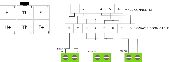
Insert the crimps into the FEMALE locking housing. The sequence should be as follows:

The housing has a small embossed ‘1’ and ‘6’ number on it, so you can orientate it as the diagram above. You can just see the ‘1’ in the picture below, on the top right of the housing. The ‘6’ is on the other side of the housing.

Ribbon cable
Old version – crimps to soldered connection
If you have the following crimp terminals and housing in your kit, click on expand and follow the instructions below.

Get the 8-way ribbon wires by stripping them off the wider ribbon cable supplied with the kit (in the ‘extruder kit’ bag). There are plenty of wires to spare. Use the two outside pairs of wires from the ribbon cable for each end of the heater cartridge – four in all. This is to increase the current capacity. The wires across the ribbon cable in order go like this:
- Heater cartridge Wire 1
- Heater cartridge Wire 1
- Thermistor
- Fan + volts
- Fan Ground
- Thermistor
- Heater cartridge Wire 2
- Heater cartridge Wire 2
Heater wires 1 and 2 are arbitrary – the cartridge has no polarity.
This order is designed to minimise the risk of cross wiring the different circuits to the hotend. Since the fan polarity is important, this wire arrangement makes it easy to flip the +ve and ground wires to the fan.
Crimp terminals onto the heater cartridge wire pairs, and onto the thermistor and fan wires.

This step is easiest with the correct tool, such as this one http://www.rapidonline.com/Tools-Equipment/Ratchet-Action-Crimp-Tool-Ht225d-85-0262 If you do not have such a tool, this advice is worth following http://www.youtube.com/watch?v=KEm2PuHBt4Y
Push the terminals into the female housings and fit these to the male header strip.

Current version – crimps and housing
If your kit includes a 3×2-way male connector, continue with this section.

Get the 8-way ribbon wires by stripping them off the wider ribbon cable supplied with the kit (in the ‘extruder kit’ bag). There are plenty of wires to spare.
Using the FEMALE crimp terminals, crimp them onto the ribbon cable wires. The 4 (four) middle wires of the ribbon cable are twisted into 2 (two) pairs to carry the required current to the hotend cartridge heater.
Push the crimps into the MALE housing. The housing has a small embossed ‘1’ and ‘6’ number on it, so you can orientate it as the diagram above.

Connecting up
Bend the wires up the side of the heat sink. Do not pull them tight – they need a little slack to accommodate movement and expansion. Attach them at the top of the heatsink with two cable ties chained together, one of them running through the top slot in the heatsink.
Trim the excess off the cable ties.
Use a meter to check that the resistance between the wires and the aluminium block is infinite and that nothing is shorting.
Also check the resistance of the heater cartridge and the thermistor by measuring from the far ends of the wires. The Mendel heater should be just under 3 ohms or the Huxley just under 7 ohms. The thermistor should be about 100K at room temperature.
Installation
Nozzle mounting brackets
If you haven’t already done so for another hot end, you now need to fit the nozzle mounting brackets:
 |
|
| Hardware | Quantity |
| M3x25mm Cap Screw | 4 |
| M3 Nuts | 4 |
| Printed Nozzle Mount Front | 1 |
| Printed Nozzle Mount Rear | 1 |
You’ll notice the nozzle mounts are slightly different. The front mount has circular holes for housing the head of the cap screw, the rear mount has a hexagonal hole for the M3 nuts. The mounts are otherwise identical, so it doesn’t really matter which way around you put the mounts on.
Insert the cap screws through the holes in the front nozzle mount, through the holes in the x carriage and secure using an M3 nut in the rear nozzle mount.

Fitting hot ends
Then use the M3x16mm cap screws in the aluminium cooling block to attach the extruder hot end to the X carriage of your Mendel. The PTFE tube clips into the printed vertical channel in the X carriage. The springs should fit underneath the lip of the x carriage. Therefore the order is cap screw, x carriage, (optional M3 washer), spring, heat sink block.

The optional M3 washer lets the springs sit flat against the printed X carriage. Fan and heatsink removed in the picture above only to show mounting, DO NOT remove yours. Make sure your hot end heater cartridge is fully inserted into the heater block, NOT like the picture!
Generally, you can fit the hot end in any of the available slots; you set the final position of the nozzle on the corner of the bed using the M206 gcode (instructions in ‘Printing’). If you’re building a Tricolour, our standard layout is to fit the first extruder on the front left space.
Finishing off
Put the free end of the PTFE tube in the extruder drive – the tube should run outside the machine, not between the threaded rods. Secure it with the printed tongue, placing it in the available slot. The thin end of the tongue goes towards the outside, locking the slotted brass union in place.


The above pictures show filament in the drive and tube already; the tube can be fitted and released with or without filament in it.
Twist the ribbon cable loosely round the PTFE tube to the top, as shown in the picture at the top of this page. Wrap it 10 turns. Do not pull it tight.
Attach the glass plate to the bed with the four foldback clips.
Tricolour Mendel
Build just one hot end at the moment; any mistake in construction will not be repeated when you build the others! Mount the hot end in the front-left mounting point on the X carriage; this is our standard position.
The Tricolour Mendel needs three hot ends in total. However, we recommend you finish the Mono build instructions, commission your printer and get some experience using it as a Mono, before moving on to the Tricolour build instructions.