| Connect the power wires. The spade connectors plug into the Shield, and the ends with ferrules go in the spare screw terminal block on the 5V regulator board. CHECK THE POLARITY IS CORRECT! |
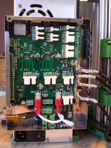 |
| The connections to the shield can now be made, following the wiring diagram above, starting from the bottom with the second hot end. NOTE: Error in picture – the second hot end should be plugged into the bottom set of pins, thermistor 2 and heater 2, to the right of the +V spade connector. See wiring diagram above. |
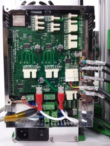 |
| The second extruder drive. |
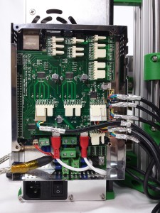 |
| The first extruder drive. |
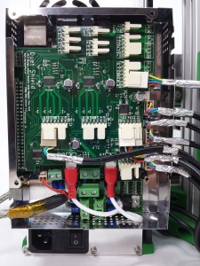 |
| The proximity sensor loom needs to be rewired, where it connects to the shield board. Remove the crimps from the two housings; press a small point into the rectangular hole in the housing to disengage the tab on the crimp, then you can pull on the wire to remove the crimp from the housing. Once out, bend the tab on the back of the crimp back up a little, so the crimp stays in the housing once it’s replaced. Then put them back in in the correct order for the shield. The order, top to bottom, is green, blue, yellow, red, ie the same order as the proximity sensor end. You can use the same housings, though one will hang over the edge, as it shows in the picture. |
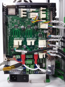 |
| The first hot end. |
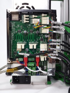 |
| The fans. |
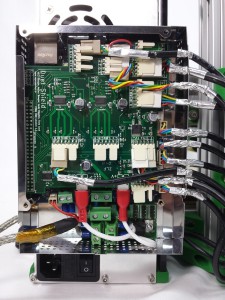 |
