
Making RepRap prints stronger without doing a lot of work.
The other day a tweet about filling the interior of RepRap prints with more plastic after the print is finished prompted me to look at an old idea of mine from 2005 for reinforcing prints with printed vertical columns.
It occurred to me that this could be generalised to make prints that acted like glass-fibre or carbon-fibre reinforced resin for extra strength. Think about what happens if, in the CAD system, you subtract a thin cylinder (say 0.5mm in diameter) from the interior of a part to be printed. When the part is sliced the slicer will surround the cylinder with solid material automatically, making it like a length of strong fibre embedded in a weaker material (the print’s infill).
If you don’t know anything about the stresses the part will be subjected to, but just want to make it generally stronger without setting the infill to 100%, you could just subtract a bunch of random cylinders from it and rely on the slicer and the printing process to make those cylinder ‘fibres’ automatically. This would be rather like making the object from a resin composited with glass-fibre wool or random chop.
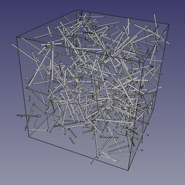
So I wrote a FreeCAD Python macro to generate the union of a load of random cylinders with their centres distributed in a pre-defined cuboid volume:
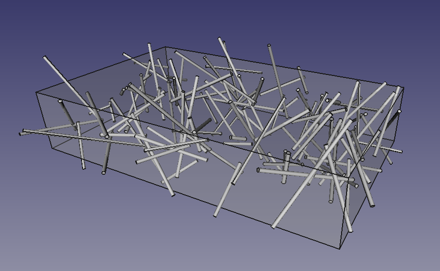
If the cuboid surrounds the part you want to reinforce, then you just subtract the resulting cylinder pattern from it:
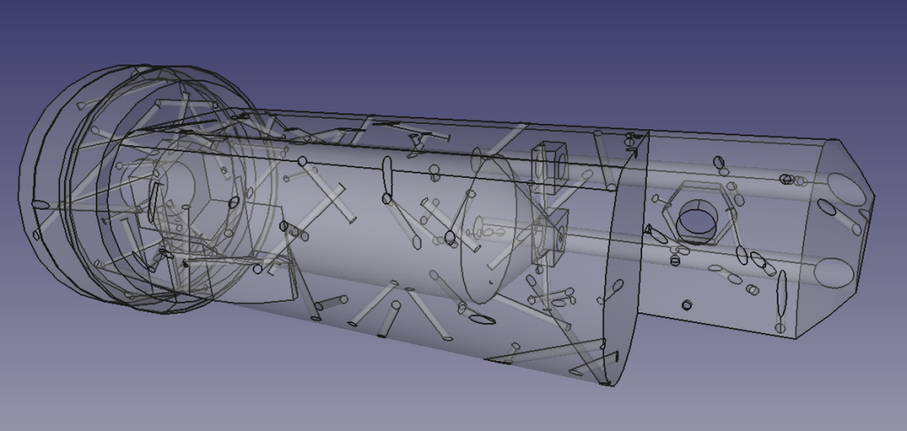
(The macro is in our Github repository) Of course, angled cylinders will be layered, but they should still be a lot stronger than infill. Also, if your printer can handle two materials you could print the part out of a weaker material, and fill the cylinders with a stronger one. I don’t think it matters (except maybe for appearances) that some of the holes come to the surface.
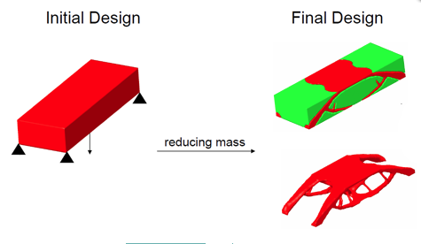
Taking the idea further, there are quite a few systems that will start with a CAD design, apply forces to it and work out the internal stresses using finite element analysis, and then erode regions with low stress and swell regions with high stress to optimise the shape of the design to give the strongest result with the lowest mass. Here’s an example:
But you may not want to change the original shape for aesthetic or other reasons. You can still apply the internal reinforcing fibres idea to a print though. Here’s FreeCAD doing an FEA stress analysis of a simple rectangular beam encased at the left end, and weighed down at the right:
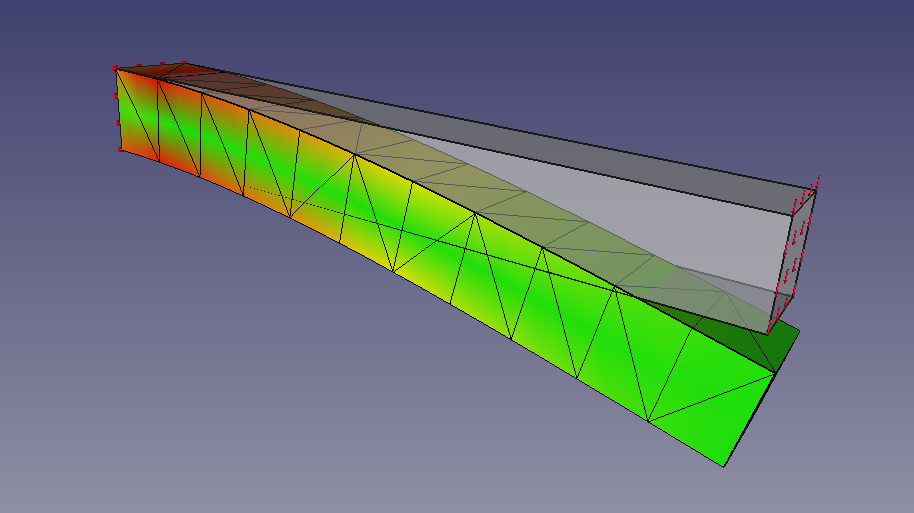
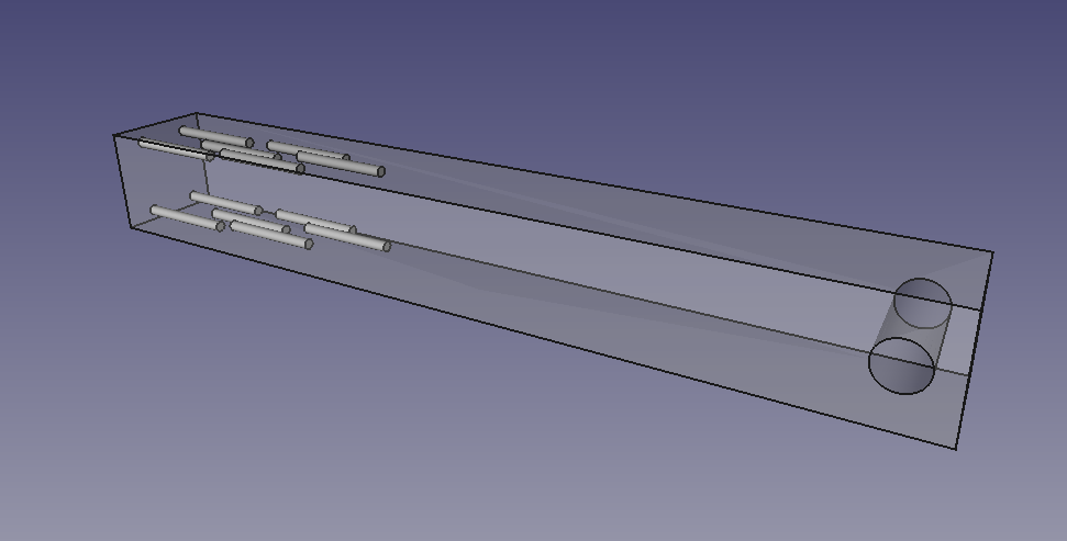
As you would expect, the maximum tensile and compressive stresses are at the top and bottom of the beam next to the encasement where the bending moment is greatest. By hand I added some internal cylindrical voids in the regions of maximum stress (also a hole at the other end to hang a weight from):
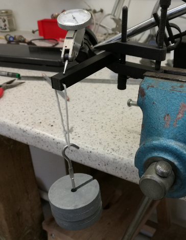
Here is the experimental set-up. I printed the beams 20mm longer (without any reinforcement in either extension) at the left hand end to give something to grasp. They were held in a toolmaker’s clamp and clocked-up with a dial gauge. Weights were added on a loop of string [Bowyer’s Law – all valid experiments must include at least one (1) length of string]:
And here are the results. The beams were printed in PLA with 20% infill sliced using Cura. The blue line is the control beam with no reinforcement; the orange is the beam with the thin cylindrical voids:
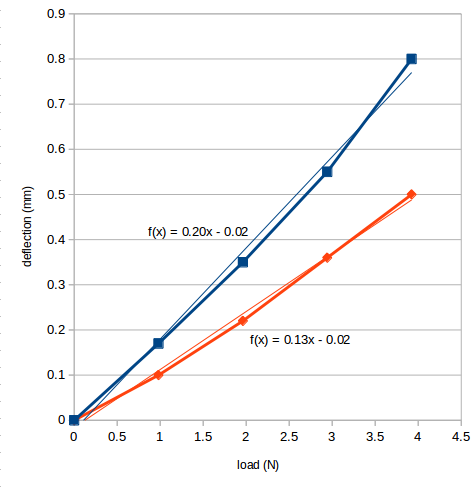
The load-deflection curves are slightly non-linear as would be expected for plastics, which are not Hookean materials. Simplifying to the least-squares-fit straight lines, the stiffness of the un-reinforced control beam is 5.0 N/mm, but the stiffness of the beam with the reinforcing cylindrical voids is 7.7 N/mm (those are the reciprocals of the graph gradients). That’s a 54% improvement.
Next I will write some code automatically to add reinforcing cylinders to regions where the FEA says there is high stress. Of course, other shapes than cylinders could be used, like thin sheets, thin ellipsoids and so on, depending on the geometry of the part, and on the shapes and nature of the stresses. Similarly material could be saved by subtracting larger shapes to make voids in regions of low stress.
Update 30-11-2018
To give some idea of the extra material added the mass of the control beam was 6.06g and of the reinforced one was 6.52g, so 0.46g of extra PLA was deposited around the cylinders. The beams were 10mm x 10mm x 100mm.
Connect with us
Keep up to date on the latest RepRap Ltd news:
Does this hold universally and equally across the different types of infill and how does percentage of infill play into it? Intentional voids are used to strengthen parts in many applications, take for example the Rapid Jack (https://andersenhitches.com/Products/3620–rapid-jack.aspx), but conceptually how does one separate the random intentional cylindrical voids from infill. Wouldn’t this imply the strongest infill is a set of random cylindrical voids? And where does it become too many voids and lose strength?
It wouldn’t make a part with 100% infill stronger; it would weaken it. Unless the Rapid Jack is 3D printed (which I don’t think it is), then I think the holes are to reduce material and to assist with mould cooling rather than to strengthen it. If it could be made solid, it would be stronger, because (ignoring gravity) a solid thing is always stronger than the same thing with holes in it (though often not by much).
The key to this idea is that localised solid is stronger than 3D print infill in the same place, because infill is mostly air. So, by adding very thin cylindrical voids (which the slicer will surround with solid, no matter how thin they are) you can make something stronger without greatly increasing infill density or print time. You can do this throughout a volume or, better, just in areas that you know will be subject to high stress.
Why not just make the infill automatic less dense in lower strength areas?
Like green is 10% infill red is 90% or 100%.
Yes you could do that. But the fibre idea allows finer control, and it also allows you to align the fibres with the direction of maximum stress.
Where the test pieces printed standing up or laying down? Did they break at 4N or were you just measuring deflection?
They were printed flat, with the reinforcing fibres at the top and bottom of the print. The reason I stopped at 4N was that that was just less than the maximum deflection on the dial gauge. They were still deforming elastically at that point, in the sense that the removal of the load returned the deflection to zero.
Would it make sense to use a construction with small 3d printed tubes zigzaged arund a square 3d printed tube only to prevent bending of a squared rod (eg. 15×15 mm). This 3d printed construction could then be inserted in a hollow squared tube.
Yes – that would probably work. But the best tests are to either do the FEA or (better whenever possible) an actual loading experiment.
Enlightening work!Can these hollow tubes intersect? Can the thickness of the hollow tube be artificially controlled? I think the thickness of the hollow tube will have an effect on the structural strength.
Yes – the random ones do intersect sometimes by chance. That seems fine. Tube diameter is a parameter that the user can control.
Hi, I decided to give this a shot but I’m having an issue with it. I’ve got the cylinders made in the model using FreeCAD, but now there’s a bunch of holes on the outside of the model. Obviously that’s gonna happen, but I was wondering if there’s a way to make it so that it leaves say a 1mm shell around the whole outside of the model so that there’s no random holes visible from the outside of the model.
https://imgur.com/a/7jAgmdh
Avoiding the holes appearing at the surface for the random pattern would be quite difficult. Essentially what you would have to do is to intersect the pattern with a shrunken version of the object before subtracting them from the object itself. But “shrunken” does not just mean “scaled by a factor of 0.9”. It means taking the Minkowski difference of the object with a sphere of the required radius, which is an extremely hard geometric calculation in general. See https://en.wikipedia.org/wiki/Minkowski_addition
Why don’t you make a copy of the bar, shell it by a certain (thin) thickness, and unite it with the original bar with the holes?
That is effectively Minkowski difference. It’s fairly easy to compute for a plane faceted design, less so for, for example, a NURBS surface.
Nice work Adrian,
Minkowski difference is not that hard if using the right tools e.g. OpenSCAD 😉
Playing with it now. I’ll report later.
Cheers.
I think adding lots of small cylinders will increase the building time drastically comparing with regular linear grid of infills (circular movements vs. linear motions of the motors). At some point, more dense infills could be equally as strong as the cylinder voids but faster at the expense of using more materials. But with the PLA price so cheap , I think saving time may be more valuable.
It increases it a bit, but not drastically. See also:
https://hackaday.com/2019/02/06/finite-element-analysis-results-in-smart-infill/
Hi Adrian,
Would this technique, which if I am not mistaken is used with Fused Deposition Modeling (FDM), still be valid with MJF (Multi Jet Fusion) or SLS (Selective Laser Sintering) or SLA (Stereolithography) printers?
Could this process make the printed object more fragile?
Or does it rely on the slicing process and work well in all cases?
Thx Maurice
I think the technique would work on any 3D printing process in which the interior of the print has a low density of infill. It wouldn’t work for processes that use solid infill.