
We are developing a multi-filament drive to a single nozzle hot end, as mentioned in this previous post about filament stream merging. It will require an in-line filament guillotine, and we have just finished the first version.
This is a diagram of how the whole system will work:
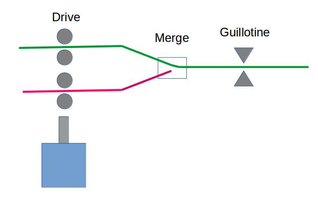
Forget the guillotine on the right for the moment. On the left a single stepper drives multiple hobbed drives for all the filaments in parallel. The pinch bearings on those drives are normally retracted, but can be forced against each filament to start driving it to the right. The selected filament is driven through a Bowden to the merge and on to the hot end.
To change a filament it is retracted past the merge, a different filament is selected to drive and pushed to the hot end.
The guillotine solves a problem with the retraction, which is that – even though you know the lengths of the Bowden tubes – you can never be sure that you have retracted the filament past the merge point because of stringing from the melt at the hot end. Stringy bits in the merge cause the whole system to jam.
So instead what this system will do is to retract past the guillotine, guillotine any stringy bits, then retract an exactly known length back past the merge. Then the new filament can be fed in the knowledge that the merge is clear. Any string past the guillotine will be pushed ahead of the new filament and can be dealt with as part of the process of purging the residue of the old filament from the hot end.
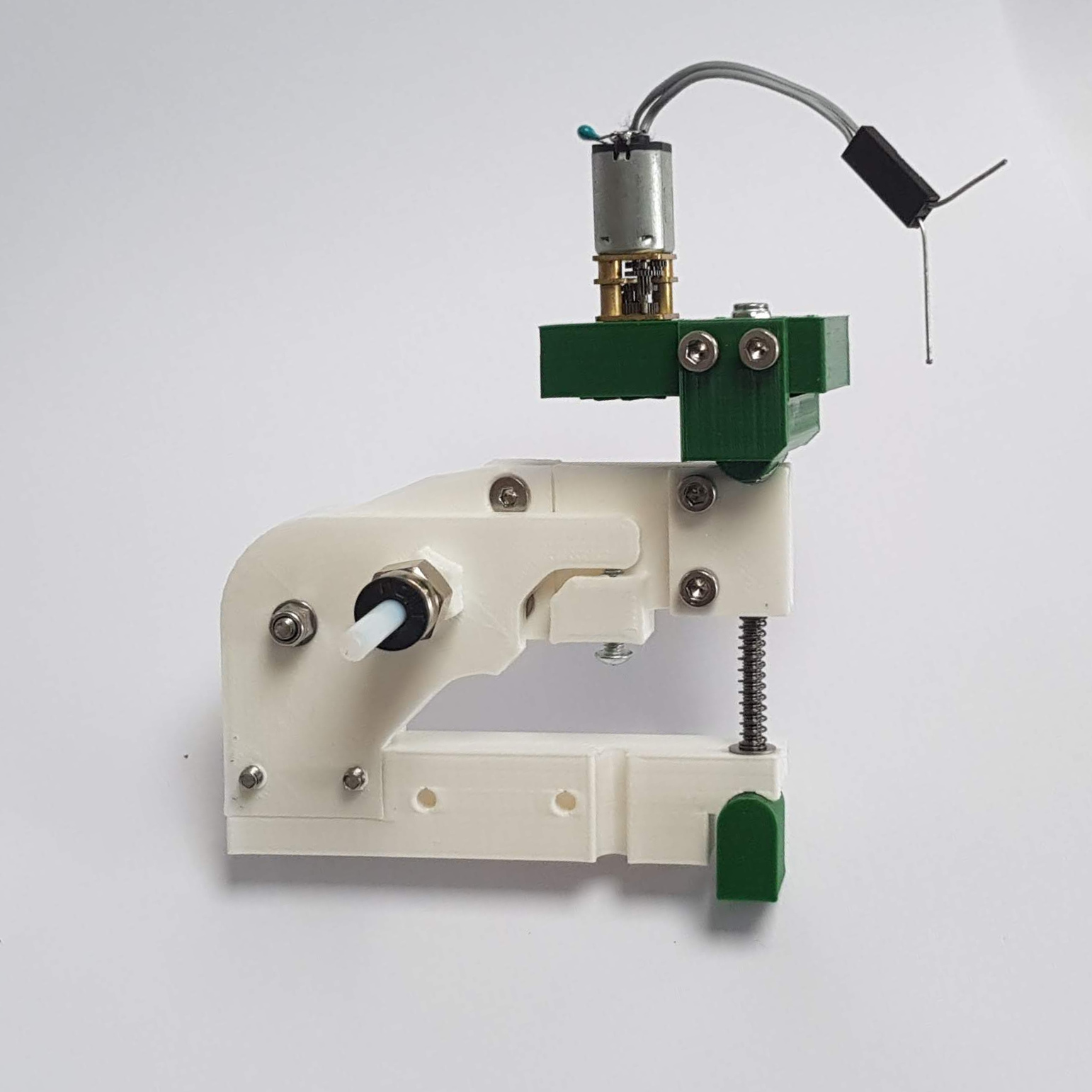
Here is the FreeCAD design for the guillotine:
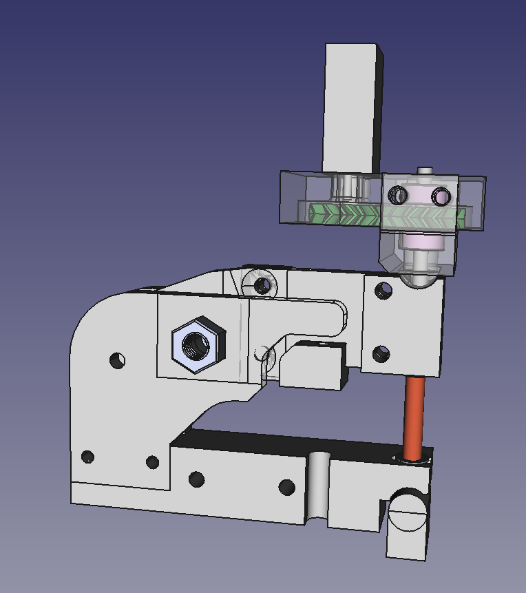
It has a scissor action driven by a small DC motor like this. Two brass discs with 2mm holes through them are mounted with the holes in-line, one in each arm. The filament normally passes through the in-line holes. The scissor action causes the holes to slide to misalignment, cutting the filament.
All the designs are in our Github repository here.
Next, and finally, watch out for a post on the drive…
Update 31 January 2019
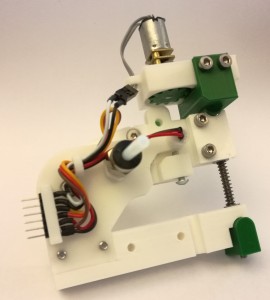
Now we have added the control and sensor wiring. The position sensor is just a 3mm phototransistor (SFH 310) and two ordinary 3mm LEDs set into opposite holes in the print on the moving and stationary arms.
As the phototransistor moves past the LEDs the voltage on the load resistor on its collector drops. The load resistor and ballast resistors for the LEDs will be in the electronics connected to the 6-way connector you can see. They will be on a standard-form Arduino Uno shield. That way we can put that collector voltage into the Arduino’s analogue-to-digital converter and tell which LED the phototransistor is looking at by having different ballast resistors on each one, and hence different brightnesses. We can also turn the LEDs on and off by putting them on Arduino outputs, so we can take differential readings to reduce interference from ambient light.
Connect with us
Keep up to date on the latest RepRap Ltd news: