Goal
| By the end of this section, you will have assembled the extruder drive. |
 |
Extruder assembly
The extruder pushes the filament into the Bowden tube, and on down into the hot end.
The design files for the extruder drive are held here on Github.
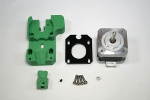
Drive block
You will need the following parts:
| # |
Component |
Qty |
Type |
| 1306 |
Drive block |
1 |
Printed |
| 1310 |
Small gear |
1 |
Printed |
| 1307 |
Drive block spacer |
1 |
Laser cut |
| 408 |
NEMA 17 stepper motor |
1 |
Hardware |
| 153 |
M3x4mm grub screw |
1 |
Extruder |
| 257 |
M3x12mm cap head screw |
4 |
Fastener |
| 258 |
M3 nut |
1 |
Fastener |
|
 |
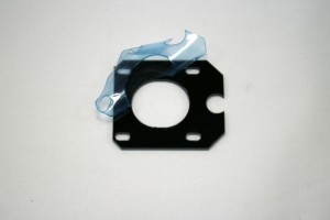
| Remove the protective film from the acrylic spacer. |
 |
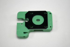
| Line up the drive block spacer with the drive block, as shown. |
 |
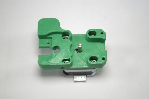
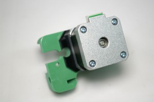
| Fit the motor to the drive block. Note the orientation of the motor wiring connector, relative to the drive block. |
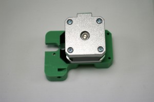 |
| Turn the block over, and fasten the motor with four M3x12mm cap head screws. Don’t fully tighten these; the motor, spacer and block need to be able to slide. |
 |
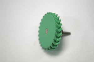
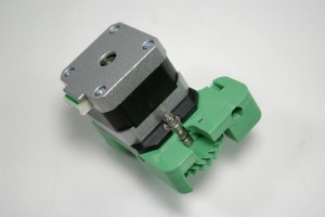
| Take the small gear, and put the M3 nut in the nut trap. |
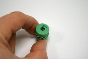 |
| Screw the M3x4mm grub screw into the M3 nut a couple of turns. |
 |
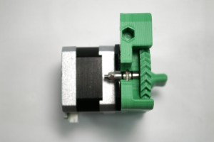
| Align the grub screw with the flat on the motor shaft, and push the small gear onto it. |
 |
| There should be no more than 1mm clearance between the bottom of the small gear and the face of the drive block. Fully tighten the grub screw. |
 |
Large gear
You will need the following parts:
| # |
Component |
Qty |
Type |
| 1311 |
Large gear |
1 |
Printed |
| 113 |
M3x25mm hex head screw |
1 |
Extruder |
| 423 |
MR93ZZ bearing (9mm diameter) |
2 |
Extruder |
| 448 |
Hobbed insert |
1 |
Extruder |
| 212 |
M3 plain washer |
1 |
Fastener |
| 204 |
M3 Nylock nut |
1 |
Fastener |
|
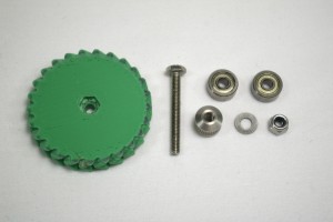 |
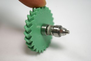
| The assembly order for the large gear is M3x25mm hex head screw, Large gear, MR93ZZ bearing, Hobbed insert, MR93ZZ bearing, M3 plain washer, M3 Nylock nut. |
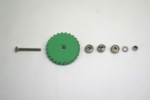 |
| To assemble, push the M3x25mm hex head screw through the large gear. Fit the MR93ZZ bearing followed by the hobbed insert. Tighten the hobbed insert against the bearing. This will pull the hex head of the screw into the nut trap in the large gear; make sure it lines up with the nut trap first. Tighten the hobbed insert as tight as possible with fingers, but make sure the bearing can still turn. |
 |
| Then add the second MR93ZZ bearing, the M3 plain washer and the M3 Nylock nut. Tighten the Nylock nut onto the washer, again making sure that the bearing is free to turn. You may find turning the M3 washer around will help (they tend to have a slightly different shape on each side), if the bearing is unable to turn. |
 |
Idler lever
You will need the following parts:
| # |
Component |
Qty |
Type |
| 1309 |
Lower Lever |
1 |
Printed |
| 1308 |
Upper Lever |
1 |
Laser cut |
| 257 |
M3x12mm cap head screw |
3 |
Fastener |
| 212 |
M3 plain washer |
1 |
Fastener |
| 279 |
623 bearing (10mm diameter) |
1 |
Extruder |
| 1250 |
Idler spring |
1 |
Extruder |
| 1185 |
M4 washer |
1 |
Extruder |
| 1193 |
M4 nut |
1 |
Extruder |
| 650 |
M4x35mm button head screw |
1 |
Extruder |
|
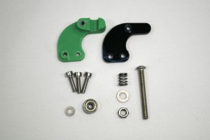 |
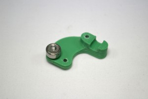
| Start by taking the printed lower lever, and insert a M3x12mm cap head screw, as shown. |
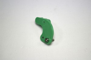 |
| Turn it over, and fit the 623 bearing, then M3 washer, on the screw. |
 |
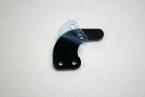
| Take the acrylic upper lever, and remove the protective film. |
 |
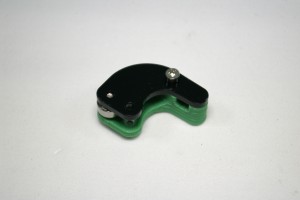
| Place this on the lower lever. Screw the two levers together with another M3x12mm cap head screw. Check that the 623 bearing can still turn freely. |
 |
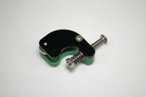
| Fit the idler pressure screw. Push the M4x35mm button head screw through the lever arm, then put the M4 washer, idler spring and M4 nut on the screw. The remaining M3x12mm cap head screw will be used to connect the idler to the drive block. |
 |
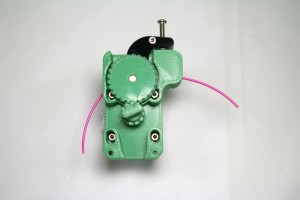
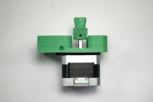
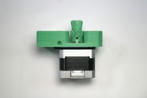
Assemble the extruder drive
| Take the extruder body. Line up the large hole in the printed drive block and the acrylic drive block spacer. Move the motor as far away from the hole as possible, to give the large gear clearance to go in. |
 |
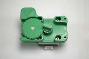
| Push the large gear in from the other side. This can be quite a tight fit! |
 |
| When in the correct place, the teeth of the hobbed insert should line up with the two small holes in the extruder body. This is where the filament runs, so these need to line up. |
 |
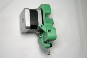
| Push the motor towards the large gear. The small gear should engage with the large gear. Turn the handle on the small gear to check the gear rotation is smooth with the large gear, then tighten the four M3x12mm cap head screws that hold the motor to the drive block. The two under the large gear can be difficult to access, without a ball-end Allen screw, but they don’t actually have to be tight for the drive to work. |
 |
| Take a piece of filament, and make sure that it passes through the drive, and engages with the hobbed insert. Adjust the large and small gear as necessary. Time spent getting this perfect will save you time later! |
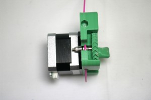 |
| Now attach the idler. This will push the filament onto the hobbed insert, so the teeth on the hobbed insert will grip the filament, and can push it firmly into the hot end. Push the M4 nut into the nut trap on the end of the drive block. |
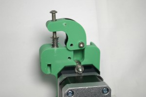 |
| Push the idler into the drive block. Take the remaining M3x12mm cap head screw, and screw it through the idler, and into the drive block. It should go through the drive block, and engage in the acrylic lower lever on the other side. |
New picture needed |
| Test the extruder drive with a piece of filament, and set the tension. You don’t want too much tension on the idler, or the motor will struggle to move the filament, but too loose and the teeth will not grip the filament. |
|
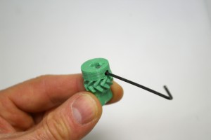
| A good test is to hold the filament as tight as you can between thumb and index finger, and turn the handle on the small gear. Adjust the tension so it is still easy to turn the small gear, but the extruder pulls the filament through your fingers. |
New picture needed |
| If the extruder slips on the filament, small pieces of the filament will get stuck in the teeth of the hobbed insert. Subsequently, the extruder is likely to slip as it extrudes, leading to poor extrusion, and poor quality printed parts. Make sure teeth of the hobbed insert are clean, by removing the filament, slackening the motor screws, and pulling out the large gear. Clean the teeth of hobbed insert with a pointy tool, then reassemble the extruder. |
New picture needed |
The tongue
The tongue holds the Bowden tube into the extruder. Don’t lose it! You will need the following parts:
| # |
Component |
Qty |
Type |
| 1320 |
Tongue |
1 |
Printed |
|
 |
| The tongue fits into the slot in the drive block, as shown. |
 |


