Contents
Goal
By the end of this step your RepRap machine should look like this:
And in addition it will have an aluminium plate on top of the red circuit board.
Tools
You will need the following tools:
- M5 Allen key
- Cross-head screwdriver
- Multimeter
- Soldering iron and solder
Parts
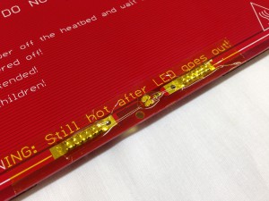
NOTE: All kits shipped after 1/8/2014 are not shipped with the 1k resistor or 3mm LED. The heated bed now comes with the LED (actually, two; one for each way around that you can wire the bed, so one will always light up) and the resistor already soldered onto the board – they are smaller, surface mount components. So the edge of your board should look like the picture below. This shows the bed from our Ormerod printer, which has pin contacts soldered on. It has also been covered with Kapton tape, for safety, which is a good idea. In the middle are the three components – 2 x LED and a resistor – and this should be the same on your Mendel heated bed, so you don’t need to solder the 3mm LED and resistor onto the board.
At this stage you will have a long piece of 20A wire (usually twin core flex, 1.6m long). Cut 0.5m off of it to use for this stage.
Get the 2-way ribbon wires by stripping them off the wider ribbon cable supplied with the kit (in the ‘extruder kit’ bag). There are plenty of wires to spare.
If that ribbon cable has a coloured stripe down one side, strip the two wires furthest from it. If it has no coloured stripe, strip from one side, then put the remaining ribbon flat on the bench and run a felt-tipped marker down one side:
This will make the wires in it easier to identify later. Set the wider ribbon aside for later use.
Main assembly
Use the countersunk screws together with four nuts and washers to sandwich the heated bed PCB between the aluminium plate and the MDF insulator. Then use a further four nuts to tighten against the nut already in place.
The zig-zag heater track on the PCB faces up towards the aluminium plate.
Make sure that the PCB solder terminals, the rectangular cut in the insulator, and the notch out of the aluminium plate all line up.
Take care not to break the lasercut springs in the corner of the insulator.
Wiring
Heated bed thermistor wiring
Bend the LED’s legs and resistor legs as shown above and insert them from the MDF insulator side. The longer LED leg goes to the end marked +.
The LED and the resistor are in series, and the two of them together are in parallel with the main heater element – the zig-zag pattern of the PCB.
Solder the LED and the resistor as shown on the aluminium plate side. You may find this easier if you prop the bed up on something clear of the bench.
Trim the wires flush with the top of the PCB using side cutters. Make sure that the connections do not project higher than the thickness of the aluminium plate, or they will foul the glass plate which will go on top of it.
Locate the 10K Glass Bead thermistor. This is very small and can get lost in the folds of the bag. It looks like this:
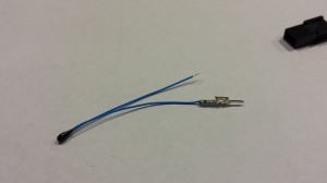
NOTE: All kits shipped after 1/8/2014 have a different thermistor. The blue material on the legs is actually insulated, so it should make installation easier. We also provide crimps, which can be used on the thermistor, for easier connection, though you can solder the thermistor legs if you prefer. See picture below.
Solder the twin ribbon wires onto the thermistor as shown above. Stagger the connections. Use the insulation stripped from the short connection to insulate the thermistor wire.
Tin the ends of the wires, then tin the wires on the thermistor, then sweat them together.
Insulate the joins with a length of heatshrink.
Strip the insulation from the other ends of the wires and use your meter to check the resistance. It should be about 10K ohms, though the exact value will depend on room temperature.
Bend the thermistor at right angles and tape it to the bed. Make sure it goes through the hole in the insulator and the hole in the PCB and touches the aluminium plate. If you like you can add a little heatsink grease to improve the thermal contact between the thermistor and the plate.
Pack the hole in the insulator with something fluffy: cotton wool or a bit of scrunched tissue both work well. Put tape over the hole. (The LED and resistor are the wrong way round in this picture – ignore them.)
Lead the wires to the edge of the bed where the two cable-grip holes are and tape them down. Use the holes on the side marked -. Note the strain relief loop; don’t run the wires straight.
Heated bed power wires
Bare the ends of the high current wire. Put heatshrink on such that it covers only a couple of mm of the bare strands. The picture shows one wire complete, the other ready to be wrapped.
Push the wires through the bed as shown and bend them flat against the tinned areas of the PCB (you may need to drill the holes out with a 3mm diameter drill first. Do this from the tinned side to get a clean hole). The wire with the black stripe goes to the side marked -. Solder the wires. Be generous with the solder (it’s giving both mechanical strength and high current carrying capacity), but again make sure that the join is lower than the thickness of the aluminium plate.
Put the glass plate on the aluminium and make sure that none of the wires nor the LED stick out and foul it.
Use the cable tie to attach the high-current wires and the thermistor wires. Again, note that the high-current wires are not pulled taught. They have a strain relief loop. Make sure they do not project too far on the MDF insulator side – if they do bend them gently flatter.
Pull the cable tie good and tight (but take care not to break the lasercut insulator), and then clip the excess off it.
Attach to the machine
Put the three long screws through the mounting holes with washers under their heads.
Put the springs on. The sequence from the screw head goes:
- M5x 40mm Cap Screw head
- M5 Washer
- MDF insulator
- M5Washer
- Spring
- M5 Washer
- M5 Nut*
- M5 Nut
The second to last nut should be tightened as much as possible, so that it compresses the spring until it hits the shank of the cap screw.
Repeat this assembly for all three mounting holes, then insert this assembly into the Y frog – with the last nut sitting directly into the recesses in the printed part. This should then be secured from underneath with the last M5 washers and nylock nuts.
Adjust the screws to get the bed roughly level (measure the heights of the corners above the Y rods with digital callipers).
Tighten the nuts against the Y carriage to secure the bed.
Fit the glass plate using the four clips and check that the Y axis moves freely back and forth.
Newer kits have a different kind of clip, which are lower profile than the foldback clips.
Then take the glass off and put it in a safe place – you don’t want to break it as you build the rest of the machine…
At this stage your machine should now look like this:


