Contents
- 1 Goal
- 2 Important: general rules for wiring up
- 3 Tools
- 4 Parts
- 5 Setting the Motor Currents
- 6 Wire routes
- 7 Attaching the control electronics
- 8 The power supply wire
- 9 The heated bed wires
- 10 The X motor wires
- 11 The Y motor wires
- 12 The Z motor wires
- 13 The endstop wires
- 14 The extruder motor wires
- 15 The hot-end ribbon cable
- 16 Connections to the controller board
- 16.1 The power wires
- 16.2 The bed power wires
- 16.3 The X motor wires
- 16.4 The Y motor wires
- 16.5 The Z motor wires
- 16.6 The extruder motor wires
- 16.7 The hot-end heater resistor wires in the hot-end ribbon cable
- 16.8 Unused connector
- 16.9 The X endstop
- 16.10 The Y endstop
- 16.11 The Z endstop
- 16.12 The bed temperature wires
- 16.13 The hot-end temperature wires
- 16.14 The hot-end fan wires
- 17 Testing
Goal
By the end of this stage your machine will be ready to commission.
All the wires from electric components in the machine run to the controller electronics.
What you are going to do is to route those wires round the frame from each component to the controller, leaving a generous extra length when the controller is reached and not at that time connecting the wire to the controller.
Then, when all the wires have been attached to the frame with cable ties, you will trim them and make the final connections to the controller.
You can route wires and attach them with cable ties as you go. You will then have to clip off those cable ties when a new wire runs on the same route and add a new one holding both wires. This is slightly wasteful, but easy.
If you click on the pictures below, you will be taken to a high-resolution version. This will help to make details clear.
If you need to identify wires (there are quite a few) then you can use the type of sticky tape called “invisible” tape. This has a surface that you can write on with a felt-tipped pen. Just put a loop of tape round the end of a wire and write “X-endstop” (or whatever) on the tape. You can either remove your labels when everything is connected and tested (neat) or leave them on (convenient if you dismantle the machine later).
Particularly useful is to tape together and label the five sets of four motor wires at their ends furthest from their motors. This helps prevent tangles when you are threading the wires, and you can easily identify them when you come to wire up the controller.
Important: general rules for wiring up
You will do serious damage to your RepRap electronics if the power is connected backwards. Other damaging mistakes are to short out high-current devices like motors and heaters, and to connect high-voltage devices like stepper drivers to signal inputs like temperature sensors.
So – in the sections below where it tells you to check things – please check them thoroughly. It is worth taking the time…
Also important for the steps below: when attaching wires to screw connectors, strip about 5mm of insulation off them, twist them between your fingers, and tin them with solder. The tinning is needed for good contact, and to ensure that fraying does not cause shorts
When wires leave a device (like a motor) or arrive at a connection (like the screw connectors on the controller) leave a small slack length (about 20mm long) for strain relief – don’t have the wires taut.
Finally, when making any changes to the wiring or any other electrical aspect of the machine, first disconnect both the power and the USB. Failing to do so could damage your electronics.
Tools
- Wire strippers
- Multimeter
- Soldering iron
- Small screwdriver
- Vice
You may also need a reel of “invisible” tape.
Parts
|
 |
Please note, two types of high current wire come with the RepRapPro Tricolour kit; 20A and 10A. The 20A wire is thicker, you have a longer length and comes with the main wiring. This should be used for the power wiring for the heated bed, Melzi and the power supply. The thinner 10A wire is for supplying power to the slave.
Setting the Motor Currents
If you have purchased a machine from RepRapPro, this is already been done for you. If not, or if they need adjusting for any reason, this process is described HERE
Wire routes
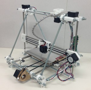
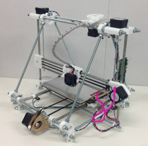
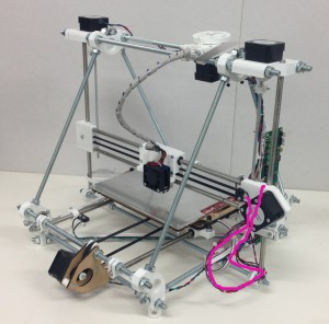
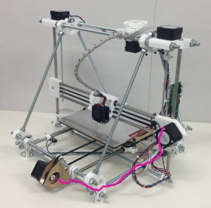
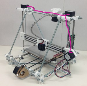
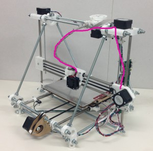
In what follows you will find the routes of the individual connections superimposed on this picture. It is taken from the back of the machine, and the side of the machine on the picture’s right is therefore the left side of the machine when it is viewed from the front in its normal working position.
Almost all the wiring runs down the triangle threaded rod to the fore of the picture, and then along the triangle threaded rod at the bottom.
Attaching the control electronics
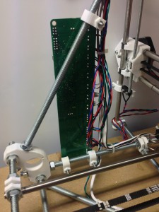
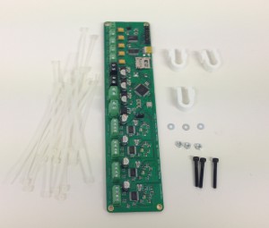
Attach the three U clips to the frame as shown. The controller board goes on the left hand side of the machine at the front (that is, the side of the frame that is on the same side as the X motor, on the side opposite the Y motor).
If you are building a Tricolour, use the Melzi controller board that is marked ‘Master’.
Adjust the positions of the U clips so that they line up with the holes in the PCB and the PCB is vertical.
Attach the board to the clips with the screws, washers and nuts. The order goes:
- screw head
- washer
- PCB
- U clip
- nut
Facing the machine from the front, the components on the PCB should be away from the triangle frame and the USB connector and SD card holder should be at the top of the PCB pointing to the front.
The power supply wire
Read through all of this section before starting work on it.
In what follows take great care that there are NO filaments of wire that are sticking out from twisted bundles. These can cause shorts, and may damage the power supply or electronics.
Detach the XLR plug from the frame vertex at the back.
If you are building the single-colour version of Mendel, do this:
Cut 55cm from the 20A wire. The rest is used for the heated bed and power supply. Bare the high-current wire ends, and split each end in two equal halves. Twist those halves separately.
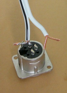
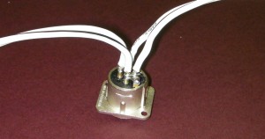
The pin numbers are embossed on the black part of the plug, next to each pin.
Solder the two from the wire with the black stripe (the Ground – GND wire) to Pin 1 and the plug shell tab.
Solder the two from the plain wire (the +12 volt wire) to Pins 2 and 3.
The picture above shows the GND connections made, and the +12 volt connections about to be made. The unsoldered fork in the picture going to Pins 2 and 3 is shown a little long; the bared wires need to be about 2/3 the length shown.
Trim the excess wire from the tab with side cutters.
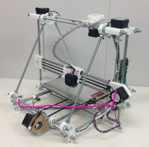
Fit the XLR plug back in the machine. The picture above shows the route of the power wire coloured pink. Leave a small loop at the XLR plug free for strain relief. Attach it with tape or cable clips to the bottom rung of the triangle, but leave the controller board end free for the moment.
If you are building the single-colour version of Mendel skip to the next section.
If you are building the multi-material/multi-colour Mendel you need two power cables, not one.
Please note, two types of high current wire come with the RepRapPro Tricolour kit; 20A and 10A. The 20A wire is thicker, you have a longer length and comes with the main wiring. This should be used for the power wiring for the heated bed, Melzi and the power supply. The thinner 10A wire is for supplying power to the slave.
The thicker 20A wire going to the master controller board is 55cm long, and the thinner 10A wire for the slave controller that is 50cm long. Wire one into the tab (black stripe) and Pin 2 (white), and the other to Pin 1 (black stripe) and Pin 3 (white). You may need to remove a few strands from the wires to reduce their diameter so they fit in the holes in the plug. Then connect Pin 1 and the tab with a small piece of thick wire. Do the same with Pins 2 and 3.
Fit the XLR plug back in the machine and run the longer master power wire as described for the Mono machine. Run the shorter slave power wire along the frame triangle base to the slave controller position. Make sure that the two free ends of this wire are separated, and wrap a little tape round the ends to insulate them temporarily.
The heated bed wires
Bare the ends of the two thin wires from the bed (the thermistor wires) and use your meter to check the resistance between them. It should be about 10K ohms (though this will depend on room temperature).
Push the meter probes in the ends of the thick wires (the bed heater PCB). The resistance should be about 1.5 ohms.
Run the power wire and the thermistor signal wire from the heated bed along the route shown.
Check that the bed of the machine can run freely from one Y extreme to the other without the wires pulling taught and without their catching on anything (particularly the M5 screw that drives the Z axis and the endstop).
Again, don’t attach the wires to the controller for the moment.
The X motor wires
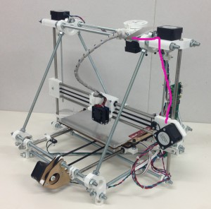
Run the X motor wires along the route shown.
Leave a generous loop in free air. Remember that the Z axis has to be able to move up and down its full length. It’s helpful to move the Z axis to the very top of the frame to ensure you have enough wire.
Don’t attach the wires to the controller.
The Y motor wires
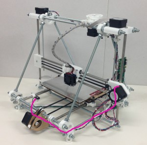
Run the Y motor wires along the route shown. They attach to the bottom threaded rod of the frame at the back. Again, don’t attach the wires to the controller.
The Z motor wires
The two Z motors are wired in series as shown in the diagram above. It doesn’t matter which motor in the diagram is the left one and which the right – the result will be the same.
Run the Z motor wires along the routes shown. Make the joins where indicated.
To make the join bare about 10mm of each wire. Put a short length of heatshrink on one. Form each end into a V (blue wire), hook them together, and then close the Vs (red wire). Solder the join (with the heatshrink further away than shown – you don’t want to shrink it prematurely).
Move the heatshrink over the join and shrink it with the hot barrel of the soldering iron (don’t use the tip – that will make a mess of solder on the outside of the heatshrink.)
Don’t attach the wires to the controller.
The endstop wires
Cut the ends off the motor wires at the controller board end. Make sure you leave a generous length on each to connect to the controller. If you taped and labelled you motor wires, put new labels just on the motor sides of the cuts before you make them.
Connect your endstops using two wires each. It is a good idea to use a different colour for each axis as this will make it easier to get the endstops connected to the correct input. You should now have plenty of multi-colour wires trimmed from the stepper motors.
The diagram shows a switch with a lever. RepRapPro Mendel works equally well with levered and un-levered microswitches.
You will probably find it easiest to connect the wires to the endstops with them removed from the machine. Unscrew the three h-shaped clips.
For each microswitch, solder a separate wire to each of the outer legs of the switch, then cover with some heatshrink to insulate the joint. These are the NC (Normally Closed) and C (Common) connections; RepRap expects the switch to open when the endstop is hit.
Put the endstops and their h clips back on the machine.
The X endstop wires
The X endstop wires run along the same path as the X motor wires.
Cable clip all the wires together where they loop free in the air. Get all wires in the loop the same length for neatness (Hint: don’t pull the cable ties fully tight. Then you can slide the wires through them to get everything neat before tightening.)
Don’t attach the wires to the controller.
The Y endstop wires
The Y endstop wires run along part of the route of the Y motor wires.
Don’t attach the wires to the controller.
The Z endstop wires
The Z endstop wires run along the route shown. Leave a good loop from the switch to the point where it first connects with the frame. You will need to adjust the height of the switch.
Don’t attach the wires to the controller.
The extruder motor wires
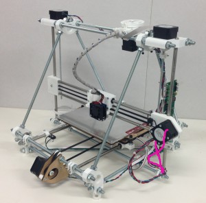
Run the extruder motor wires along the route shown.
Don’t attach the wires to the controller.
The hot-end ribbon cable
The hot-end ribbon cable should already be loosely wound round the PTFE filament feed tube.
Attach it to the frame along the route shown.
Don’t attach the wires to the controller.
Connections to the controller board
First make sure that all the moving parts of the machine can move freely for their full travel without fouling or snagging any of the wiring. Remember that the entire X axis has to be free to move vertically.
If you have attached all the wires with tape, now is the time to go round the machine cutting off the tape (don’t cut the wires…) and attaching the wires permanently with cable ties.
What you are going to do is to trim the wires to length, twist them, tin them, and attach them to the appropriate screw connector. When a wire is in its connector the insulation should abut (but not enter) the metal part of the connector. There should be no bare wire visible.
When you twist and tin the ends of the wires, put them in their connector to check the length. If any are a little long, trim them with side cutters.
When you tighten the screws in the controller board’s connectors take care that
- Your screwdriver doesn’t slip and damage the board,
- You don’t put excessive twist stress on the board or push against it too hard – support it with your free hand.
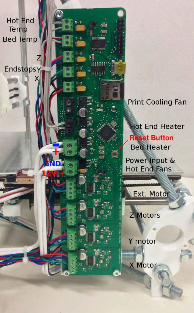
The port marked ‘fan’ is NOT for the hot end fan. This port is for an optional cooling fan that points directly at the print. This is useful for printing small parts and helps with detailed features when printing with PLA. The hot end fan connects directly to the 12V supply of the Melzi, so that it runs all the time.
The power wires
Cut the wires to length so that they will reach the power connector on the board. The GND (black stripe) wire goes to the top of the connector and will have to be a little longer.
Bare the ends of the wires and twist them tight. Make sure there is a good length of wire to go into the screw terminal (about 10mm), but not so much that there is bare wire outside of the terminal. Tin the bare wire, but don’t use too much solder, or the result will be too fat to fit in the connector.
Screw the wires into the power connector. As mentioned the GND wire with the black stripe goes to the top, the plain wire to the bottom.
Don’t do the power connector up tight – you are going to have to connect the hot end fan wires to the same connector in a minute.
This is the single most important electrical connection in the machine. If you get it wrong expensive bad things will happen. Take a moment to double check it.
The bed power wires
These go to the connector just above the power input connector. Again the black stripe is the low voltage one and goes to the top. The plain wire is the +12 volts wire and goes to the bottom.
Connect the wires in exactly the same way as the power wires, but do these ones up tight. Use a finger to support the back of the Melzi PCB when you are tightening screws – don’t let it bend.
The X motor wires
These go to the bottom connector. From the bottom upwards the sequence is Black, Green, Blue, Red.
The Y motor wires
These go to the connector above the X motor connector. From the bottom upwards the sequence is Black, Green, Blue, Red (that is, the same as X).
The Z motor wires
These go to the connector above the Y motor connector. From the bottom upwards the sequence is Black, Green, Blue, Red (that is, the same as X).
The extruder motor wires
These go to the connector above the Z motor connector. From the bottom upwards the sequence is Black, Green, Blue, Red (that is, the same as X).
The hot-end heater resistor wires in the hot-end ribbon cable
A reminder from when you wired the hot end: the wires across the ribbon cable in order go like this:
The hot-end heater cartridge wires come in pairs – you connected two wires to each end of the resistor to get a good current carrying capacity.
The hot-end heater cartridge wires go to the connector above the bed power wires, labelled ‘hot end’
Split them off from the hot-end ribbon cable, bare the ends, twist the pairs together, tin them, and fit them in the connector. The polarity doesn’t matter – you can connect them either way round.
Unused connector
The connector above the hot-end heater resistor wire connector labelled “fan” is not used. DO NOT connect the hot end fan to it (see below).
The X endstop
The X endstop wires connect to the connector above the unused connector. The polarity doesn’t matter – you can connect them either way round.
The Y endstop
The Y endstop wires connect to the connector above the X endstop connector. The polarity doesn’t matter – you can connect them either way round.
The Z endstop
The Z endstop wires connect to the connector above the Y endstop connector. The polarity doesn’t matter – you can connect them either way round.
The bed temperature wires
The wires that run along with the bed power wires connect the bed’s temperature-measuring thermistor. They connect to the connector above the Z endstop connector. The polarity doesn’t matter – you can connect them either way round.
The hot-end temperature wires
There are two wires from the hot-end ribbon cable that connect the hot-end temperature-measuring thermistor. They connect to the connector above the bed temperature connector. The polarity doesn’t matter – you can connect them either way round.
The hot-end fan wires
The hot-end fan wires in the hot-end ribbon cable DO NOT connect to the terminals marked “fan” – those are for optional additional cooling. Do not connect them to the hot end power or the bed power.
The hot-end fan wires connect to the power connector, in parallel with the 12V power input, so the hot-end fan is on all the time.
Make sure you get the polarity right. You should have marked the fan’s + and – connections when you wired up the fan. Trace them through by counting wires across the ribbon cable.
Slacken the power wire screws and connect the fan wires in parallel with the power.
Tighten these screws firmly – this connector has to carry a large current. Remember to support the back of the circuit board when you are tightening screws to stop it bending.
Never operate your RepRap without the fan connected and running. The hot end needs the cooling at all times.
Testing
Set your meter to measure resistance. Short the probe ends. You may find (particularly if your meter is not the most expensive one on the market) that the reading is not quite 0 ohms. Note down what it is – this is your meter’s idea of a dead short. Add this number to the low resistances given below.
Remember that you have a resistance (about 20kohms). You will get incorrect resistance readings if your fingers are touching wires or parts of the circuit.
Put one probe on the casing of the XLR power connector. Put the other on the cover of the SD card socket. The meter should read 0 ohms.
Measure the resistance between the two screws on the Melzi board’s power screw terminals. This may start low and then rise; this is the capacitors in the circuit charging up with the tiny current from the meter. It may level out at a few hundred ohms. Anything HIGHER than this, up to infinite resistance, is fine. Anything LOWER than this, down to 0 ohm resistance, indicates a short between +12V and -12V (ground), and MUST be fixed!
Measure the resistance between the two screws on the bed power screw terminals. This should be about 1.5 ohms.
Measure the resistance between the two screws on the hot-end heater screw terminals. This should be about 3 ohms.
Make sure all the moving axes are not touching their endstop switches. Check that each resistance on the X, Y and Z endstop connectors is 0 ohms. That is to say the endstop switches should be closed. Press each switch in turn. The corresponding resistance should rise to 5K ohms or more (the resistance of the circuit components on the controller board in parallel with the switch).
Check the heated bed temperature sensor connector. The resistance should be around 5 to 10 kilohms. This is not just the resistance of the sensor. Other parts of the circuit on the controller board are in parallel with it.
If you are building the single-material/single-colour Mendel, check the hot-end temperature sensor connector. The resistance should be around 5 to 10 kilohms. This is not just the resistance of the sensor. Other parts of the circuit on the controller board are in parallel with it.
Measure the resistance between Pin 3 on the XLR connector and the +12 volts input screw on the controller board. This should be 0 ohms.

