Contents
Micro SD card
If you have SD problems, try a different SD card, and writing files to it with a different adaptor. We supply Kingston 4GB Class 4 Micro SD cards, and have had very few problems with them; they come with a guarantee from the manufacturer.
SD cards come in a variety of sizes; we have tested cards up to 8GB. They should be a FAT32 formatted disk. It’s also possible you have a faulty Duet board, but please do the tests on this page before returning your Duet board for a warranty replacement; it will be quicker for you than a miss-diagnosed problem with the Duet board when the real problem is with the SD card.
- When you insert the SD card into your PC, you should see three folders – ‘gcodes’, ‘sys’ and ‘www’. These need to be the first thing you see, that is not in another folder on the SD card. If you have been doing the axis compensation, make sure that you haven’t deleted config.g from the ‘sys’ folder, or moved or mis-named it.
- The SD card only goes in one way into the Duet SD card slot. Facing the Duet board, with the back cover off so you can see the processor and other components, the writing on the SD card should face towards you as you insert it. You can damage the SD card slot if you force it in the wrong way.
- Have you pushed the SD card in fully? You need to poke it in past the Duet enclosure, with a small screwdriver or something similar. It should ‘click’ in. To remove it, push it in again gently until it ‘click’s again, then release and it should pop out.
- Test the SD Card as described in the Commissioning instructions HERE
- If it’s working at startup, it’s generally safe to assume it will work the rest of the time.
- If it isn’t working, update your firmware if it is an old version (we have improved the firmware to help with the problem of slow cards)
- We now supply high quality Kingston 4GB Class 4 micro SD cards, and have experienced virtually no problems with these. If you have an old, non-Kingston card, try a different micro SD card – these are widely available and quite cheap.
- It could be dirt or dust in the SD card socket. Try cleaning the SD socket. Use an electronics/PCB/contact cleaning aerosol to clean the SD socket contacts; this should dissolve and wash away any contamination, and then completely evaporate. Or see this message on the forum regarding cleaning – http://forums.reprap.org/read.php?340,309685,310840#msg-310840 .
- Are you running on USB power only? If so, see the note at the start of commissioning, regarding USB 5V power: https://reprapltd.com/reprappro/documentation/ormerod-2/commissioning/#IMPORTANT_note_about_USB_5V_power . If the voltage is below 4.7V on the 5V line, try powering the Duet from the power supply – for the moment, remove the heated bed ribbon cable and hot end connector. Put a jumper on JP10 (ATX_5V_EN) and connect the PSU, turn on, and test.
- Is the main ARM processor getting warm/hot? We’ve had a couple of people report that the SD card has shorted out the processor, due to manufacturing defects. Unfortunately, this is usually terminal.
When you send the M503 command, you may get an error code. Here’s a list of the error code definitions:
- Error code: 0 – Succeeded
- Error code: 1 – A hard error occurred in the low level disk I/O layer
- Error code: 2 – Assertion failed
- Error code: 3 – The physical drive cannot work
- Error code: 4 – Could not find the file
- Error code: 5 – Could not find the path
- Error code: 6 – The path name format is invalid
- Error code: 7 – Access denied due to prohibited access or directory full
- Error code: 8 – Access denied due to prohibited access
- Error code: 9 – The file/directory object is invalid
- Error code: 10 – The physical drive is write protected
- Error code: 11 – The logical drive number is invalid
- Error code: 12 – The volume has no work area
- Error code: 13 – There is no valid FAT volume
- Error code: 14 – The f_mkfs( – aborted due to any parameter error
- Error code: 15 – Could not get a grant to access the volume within defined period
- Error code: 16 – The operation is rejected according to the file sharing policy
- Error code: 17 – LFN working buffer could not be allocated
- Error code: 18 – Number of open files > _FS_SHARE
- Error code: 19 – Given parameter is invalid
Ethernet connection
A note about DHCP connections
DHCP is supported in firmware v1.09 or later. If the Duet is getting it’s IP address from the router, via DHCP (ip address in config.g is set by ‘M552 P0.0.0.0’ to enable this), and you can’t connect using the name of the printer (set in config.g by ‘M550 P[name]’), either your router does not support DHCP/NETBIOS naming, or your computer may be using an external DNS server, rather than using the router DNS, which would mean it can’t connect to a local ip address. Setting the Duet IP address manually should allow you to connect.
Physical connection problems
If you get no green light on the Ethernet connector, either there is no power to the Duet board (via USB or from the PSU – it can’t be powered from the Ethernet connection), or the Ethernet cable is not making contact/isn’t working, or there is a problem with the Duet board. Check power and the Ethernet cable. If you still get no green light, contact support.
Testing the connection in isolation
For testing, disconnect your computer from the rest of your network, i.e. the router/hub/wifi connection, and connect an Ethernet lead directly from your computer to the Duet. This leaves a network between just your computer and the Duet. Set up the Ethernet port of your computer so it is in the same range as the IP address of the Duet. If you are using the standard config.g, the Duet is on 192.168.1.14 (if using an SD card) and has a firmware default address of 192.168.1.10. Set the Ethernet port on your computer to 192.168.1.12, netmask 255.255.255.0, so it does not clash with either of the Duet addresses. Power the Duet just from USB, and you should be able to ‘ping’ the Duet, to test it actually works.
To ‘ping’ a network address: open a command prompt/terminal window, and type ‘ping 192.168.1.14’ (or the IP address you set in config.g). You should receive a list of sent/received data packets, which will show if the Duet is on the network. Even without an SD card, you should be able to ping 192.168.1.10 and get a response from the Duet.
You won’t be able to access the printer web interface, because your computer is not connected to the internet, but it will prove that the network interface of the Duet works. If it does not, contact support
Check network settings
To connect to the Duet, you need to edit the settings in config.g so the Duet’s networks settings are in the same range as your network, as described in the commissioning instructions HERE. The standard SD card IP defaults – from sys/config, SD-Image here github.com are:
M552 P192.168.1.14; Set the IP address
M553 P255.255.255.0; Set netmask
M554 P192.168.1.1; Set the gateway
Edit the config.g on the SD card to suit your network. If you have more than one Duet board on your network (ie more than one printer), you will also need to change the MAC address of one of the printers, as described in the instructions HERE.
Establishing connection
- If you disconnected your computer from the network, reconnect it.
- Make sure you have a working SD card (see HERE), and check the network settings.
- Connect ethernet cable to router, then to the Duet.
- Connect USB lead to Duet (this is needed for power, and can help with diagnosis), or turn on the PSU, and check that JP10 (ATX_5V_EN) has a jumper on it.
- The GREEN LED on the ethernet connection should light up on the Duet. The ORANGE LED is a indicator light for 10base-T connections – most ethernet hubs/routers/switches are 100base-T or gigabit, so it will stay switched off.
- You should be able to ping the Duet, on the IP address you set.
- You should then be able to connect to the web interface, using Google Chrome or Firefox, by typing the IP address you set in the address bar.
Resolving connection problems
- If you are using DHCP, check you are trying to connect to the right printer name, preceded by ‘http://[printer name]’. Also check that your router supports DHCP/NETBIOS naming, and your PC is not using an external DNS server and/or gateway.
- If you can ‘ping’ the Duet ip address, the Duet is on the network, and the problem is most likely with the SD card or browser. If you cannot, it may be a problem with the Duet, or the network. Try changing the ip address in config.g.
- How is the Duet set up on your network? Is your network quite complex, ie an office network, rather than a simple home network? To remove network issues as a source, connect the printer directly to your PC, via a spare ethernet port. You can then set up the printer and ethernet port on the PC on it’s own subnet, separate from the rest of the network. Since firmware v1.04, you don’t need access to the internet. you should be able to ping the Duet, and then connect via the web interface.
- Clear the cache in your browser. It may be caching javascript code or settings of the wrong version, or corrupt. For Chrome, clear the cache, particularly any downloaded files/site data: https://support.google.com/chrome/answer/95582?hl=en-GB . In Firefox, clear the settings by clearing Preferences > Advanced > Network, then clear Cached Web Content.
- It’s possible that the files on the SD card have corrupted. You may need to reformat the card (use the official formatting tool: https://www.sdcard.org/downloads/ ) and refresh the files on it. If possible, try another micro SD card. You MUST use the same version of the web server that is supplied with the firmware.
- Make sure that your router allows the Duet to run as a web server or service on your network. If it is blocking it, you would still be able to ping the Duet, but may not get a coherent response from the web interface.
- If you experience disconnections, this usually happens with poor internet access (some of the files for the web interface are fetched from the internet; the host computer MUST have internet access), or there are network issues (going through multiple routers, hubs and over wifi). Usually, when it happens, resetting the Duet and closing the browser tab, then reopening, is enough to get rid of the problem, and allow connection.
- If the above still doesn’t help, and browser produces any error messages, please contact support with any pertinent information.
Temperature sensing
Problem
- Temperature reports as -273oC, or below -10oC, or no temperature (eg T:B:25.1)
- Hot end end and/or bed temperature read 60oC at room temperature (eg T:59.5 B:63.6)
- Firmware reports a ‘temperature fault on heater …’
- Hot end or heated bed never turns on
- During printing, the heater turns off unexpectedly
Testing
Pronterface reports the temperatures in the bottom left of the window in the form ‘T:15.7 B:21.8′. ‘T’ is for the ‘Tool’ (the hot end) and ‘B’ is for the heated bed. If either temperature is below about -10oC, the firmware will report a temperature fault, and disable the heater. You will not be able to turn the heater on until the problem has been corrected, and the temperature fault has been reset. Reset the fault by resetting the Duet (press the reset button on the Duet) or, you can send ‘M562 P0’ to reset a bed temperature fault, or ‘M562 P1’ then ‘T1’ to reset a hot end temperature fault (see the reprap gcode list HERE).
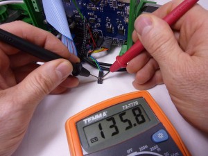
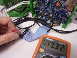
Test the wiring. Most commonly, incorrect temperature readings are a result of a poor connection in the thermistor wiring loom. This can happen at the connection with the thermistor, at any of the crimped connections, in any of the housings in the wiring loom, or even a break in the wires of the loom. The quickest way to test is to use a multimeter, and measure the resistance at the end of the wiring loom, where it connects to the Duet.
(Pictures from Ormerod 1, but Ormerod 2 is similar)
It should report the ambient (room) temperature. The following resistances relate to the following temperatures.
Hot end / Bed = Temperature
200k ohms / 20k ohms = 10oC
160k ohms / 16k ohms = 15oC
125k ohms / 12.5k ohms = 20oC
100k ohms / 10k ohms = 25oC
80k ohms / 8k ohms = 30oC
You can also replace the thermistor with a known-value resistor, to test the wiring loom. Unplug the thermistor from the wiring loom, and plug in the resistor, then measure the resistance again at the end. If it reports correctly, the thermistor may be damaged. If you don’t get a sensible reading, look for damage or failure along the wiring loom.
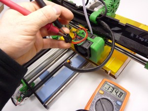
Test the thermistor. It is possible for the thermistor to break, so test it as close to the thermistor itself as possible.
(Pictures from Ormerod 1, but Ormerod 2 is similar)
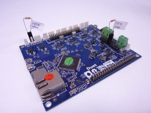
Test the Duet. If the wiring tests okay, you can test the Duet by connecting a known-value radial resistor directly to the thermistor pins, and see the temperature it reports (you can also do this using the wiring loom, and connecting the resistor in place of the resistor). For the hot end, find a 100k resistor, touch it to the thermistor pins on the Duet, and press the reset button on the Duet. Then connect to the Duet with Pronterface, or the web interface, and check the temperature. The temperature should report around 25oC.
If you have a number of different value resistors, you can check the temperature across the range. Common resistor values give the following temperatures:
100k ohm = 25oC
47k ohm = 42oC
10k ohm = 84oC
1k ohm = 173oC
470 ohm = 212oC
220 ohm = 261oC
100 ohm = 321oC
You can do the same thing to test the bed temperature, but use a 10k ohm resistor. The following resistors should give these temperatures:
10k ohm = 25oC
1k ohm = 86oC
470 ohm = 113oC
100 ohm = 181oC
The above tests should show if the problem is with the wiring, the thermistor, or the Duet.
Solution
- If you temperature is reported as ‘T:59.5 B:63.6’ or similar at room temperature, see THIS SECTION in the commissioning instructions.
- If the thermistor appears to be broken, contact RepRapPro for a new thermistor.
- If there is a short circuit, or poor connection in the wiring, check/repair/replace the damaged wiring.
- The wiring loom may not be making good contact with the Duet header pins. If you have a Duet with no keyed headers (a little plastic part around the pins that aligns the wiring connection) the crimp in the loom housing can easily get distorted. The crimps in the housings are standard Molex KK 2.54mm crimps (eg uk.rs-online.com ), and are a ramp-style connector. If the housing is not put on the pins straight, the ramp (the ‘curly’ part of the crimp) can get bent back, and a poor connection can result. You can remove the crimp from the housing quite easily, and bend them back so they have better contact. You can also bend the pins on the Duet a little, to improve contact. You can, of course, replace the crimps and housings with anything you deem better, such is the nature of a kit build.
- If you have a Duet where the hot end temperature reads -273oC, or some other very low temperature, even with a 100k ohm resistor connected, there may be a fault with your Duet. You do need to the tests above to check it is not just a broken thermistor or poor wiring, though. If a 100k ohm resistor reads below 15oC, we will replace the Duet under warranty. This fault is caused by manufacturing differences within each ARM processor at the heart of the Duet; the Analogue to Digital Converters (ADCs) on board the ARM processor can give quite variable readings at the limit of their sensitivity.
Endstop and homing problems
Problem
- Homing of X, Y and/or Z does not work correctly
- Axis moves the wrong direction when homing
- Axis does not stop before hitting the end
Solution
- Check that the motors are wired correctly; they need to be on the correct axis, and the right way around, on the Duet. See: https://reprapltd.com/reprappro/documentation/ormerod-2/wiring/
- If homing the X axis causes the x-carriage to hit the end, make sure you have put a ‘reflector’ (a piece of paper or adhesive label, like that used on the bed) to the top of the bar that sticks out from the x-motor-mount. This triggers the sensor for the X axis homing. for the sensor to work consistently.
- Check Y axis endstop wires are connected to the correct place on the Duet – it is easy to connect them to the wrong pins. They should be connected next to the Y axis motor. See: https://reprapltd.com/reprappro/documentation/ormerod-2/wiring/
- Check that the wiring loom is connected to the Y axis endstop microswitch correctly; it should connect to the outer two pins of the microswitch, NOT the central pin.
- See the following section to troubleshoot problems with the proximity sensor, particularly for Z homing problems.
Proximity sensor problems
Problem
- Homing of X and Z axes do not work properly
- Response from G31 is inaccurate, or varies, or doesn’t change
Solution
- Check your wiring of the proximity sensor, at the sensor end and the Duet end. See: https://reprapltd.com/reprappro/documentation/ormerod-2/wiring/
- Some looms were shipped with the green and yellow wires swapped where it connects to the probe. Check the order of the wires in the 4-way housing, it should be red, yellow, blue, green. If you look at the housing, as in this picture https://reprapltd.com/reprappro/wp-content/uploads/2014/05/ORM2-wiring-26.jpg (top right), you can see the crimps. Each one is held in by a small plastic tab that is part of the housing. If yours are in the wrong order, you can correct this yourself. Using a thin, sharp point (like the tip of of a craft knife), lift the tab a mm (but no more, or it will snap off!), just enough to allow the crimp and wire to pull out. You can then swap the position of the wires, and test the probe.
- Some looms were shipped with the red and blue wires swapped, which connect to the Duet, as shown in this picture https://reprapltd.com/reprappro/wp-content/uploads/2014/05/ORM2-wiring-26.jpg (bottom right). For these, press a small point into the rectangular hole in the housing to disengage the tab on the crimp, then you can pull on the wire to remove the crimp from the housing. Swap the positions of the red and blue. Before reinserting, bend the tab on the back of the crimp back up a little, so the crimp stays in the housing once it’s replaced.
- Updated your firmware, and update the files on your SD card, with the files from ‘SD-Image’ in the firmware folder. These should be kept on the same version. This should update any firmware behaviour that may be causing homing problems. See: https://reprapltd.com/reprappro/documentation/ormerod-2/maintenance/#Installation_8211_Flashing_the_Firmware
- Check that your SD card is working AT STARTUP. This is crucial, because it effects the behaviour of the proximity sensor: https://reprapltd.com/reprappro/documentation/ormerod-2/commissioning/#Is_the_SD_card_being_read_AT_STARTUP
- Check that there is no big Infra Red source near the printer, this will upset the proximity sensor. See the noted below the picture here: https://reprapltd.com/reprappro/documentation/ormerod-2/axis-compensation/#Setting_the_Z_Probe
- Check the values you get from the probe. With axis a long way from the bed, send G31. The result should be a low number, like 10. Put a piece of white paper under the sensor, very close, and send G31. The result should be a very high number, like 950. This is the normal range for the sensor.
- If you get 0 or 1023 from G31, or it varies only within a small range (ie 250 to 400) check your wiring – most likely you do not have the wires connected to the correct pins, or there is a poor connection in the wiring loom or the crimp has a poor connection to the pin on the Duet. See: https://reprapltd.com/reprappro/documentation/ormerod-2/wiring/
- If you get a constant value from G31, the board may be damaged.
If the homing seems inaccurate after all of the above, check that the Z axis is moving correctly; there could be backlash or lack of lubrication that are causing problems. Check:
- Look for binding or stalling in the z-gears
- Stiff movement of the Z axis up and down
- The z-runner-mount should only be lightly gripping the extrusion, or that will cause problems for the Z axis movement
Further testing
To test the Duet is working correctly, first check the voltages on the pins where the wires from the proximity loom connects to it (see https://reprapltd.com/reprappro/documentation/ormerod-2/wiring/#Wiring_diagram ). Disconnect the proximity sensor loom from the Duet, and test the voltage between the pins which the Green (+3.3V) wire and Yellow (Ground) wire connect to; this should be around +3.3V. You can do this with the Duet powered just from USB.
Then test the Duet is sensing the range of readings correctly. Short circuit the pin that the Red (sensor reading) wire connects to, to ground (the metal cover of the SD socket) with a piece of wire; the G31 response should be ’0 (0)′. Then put a jumper between the Red (sensor reading) pin and the pin next to it, which the Blue (modulation) ; the G31 response should be ’1021 (1021)′.
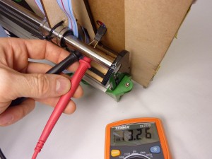
Reconnect the proximity probe and wiring. You can test the voltage on the proximity board with a multimeter. Measure the voltage with the red multimeter probe on the pins on the back of the Proximity sensor board, where the wiring loom connects to the board, and the black probe on ground, eg the metal SD card cover. Make sure the probe is in ‘4-wire’ mode by sending ‘M558 P2’. You should get something like the following:
Probe reading: 3 (4) (50mm of space under probe)
Red (sensor reading): 20mV
Yellow (Ground): 2.5mV
Blue (modulation): 1.29V
Green (+3.3V): 3.27V
Probe reading: 953 (955) (white paper close to the probe)
Red: 1.53V
Yellow: 2.5mV
Blue: 1.29V
Green: 3.27V
The red wire, which carries the sensor reading, reads half of the voltage at full saturation, as it is turned off half the time, as the probe modulates. The Blue wire carries the modulating voltage to the infra red LED in the sensor, so it also shows half the voltage. There is a voltage drop on the Blue wire, as it powers the LED.
You can also turn the modulation off, and measure the voltage on the pins of the probe. Send ‘M558 P1’, then check the voltage. You should get similar readings to these:
Probe reading: 1 (50mm of space under probe)
Red: 25mV
Yellow: 5.6mV
Blue: 2.56V
Green: 3.27V
Probe reading: 955 (white paper close to the probe)
Red: 3.06V
Yellow: 5.6mV
Blue: 2.56V
Green: 3.27V
This should show if there is a problem with the sensor, or if there a problem with a poor connection on one of the wires, or if it is the Duet.
Motor problems
Problem
- Motor does not move when commanded, when other axes do move
- Motor shudders, vibrates, or moves erratically
- Motor moves, but stops or stutters as it moves on the axis
Testing and solutions
NOTE – Extruder axis not moving? From firmware v1.04 or later, cold extrusion is prevented by default. The extruder drive will not move if the hot end temperature is less than 170C. You can override this behaviour, by sending M302. See the Calibration instructions HERE.
If there is a particular motor moving randomly, vibrating, or not moving at all, there are three areas to check:
- The motor. These are generally very reliable – we have sent out over 10,000 of them, and had about 10 faulty ones.
- The wiring. This is also generally very reliable, but it’s possible it has been put together incorrectly, or there is a break in the wiring.
- The electronics. The Duet may have suffered damage to the stepper driver.
To test, turn off the power to the printer, and swap the wiring at the Duet between two axes, eg X and Y, or Z and extruder. Make VERY sure you have connected the wiring correctly; check the wiring diagram. Turn on power, connect, and test BOTH axes. If the problem stays with the same motor as before, the issue is with the motor or wiring; if it swaps to the other motor, the problem is with the Duet.
If the problem follows the motor, turn off the printer, and replace the motor wiring on the correct pins. Then:
Check the motor wiring loom. Check that your motor wiring looms are connected to the correct pins on the Duet. We have had a few cases (in nearly 2000 kits!) where the motor loom is incorrectly wired. Compare the wiring loom, at both ends, with another, known-working motor loom; check that the colour order is the same, check that the wires are connected to the right pins of the plug into the motor. The crimps are quite easy to release from the housing, and put in the correct order.
If you have a Duet with no keyed headers (a little plastic part around the pins that aligns the wiring connection) the crimp in the loom housing can easily get distorted. The crimps in the housings are standard Molex KK 2.54mm crimps (eg uk.rs-online.com ), and are a ramp-style connector. If the housing is not put on the pins straight, the ramp (the ‘curly’ part of the crimp) can get bent back, and a poor connection can result. You can remove the crimp from the housing quite easily, and bend them back so they have better contact. You can also bend the pins on the Duet a little, to improve contact. You can, of course, replace the crimps and housings with anything you deem better, such is the nature of a kit build.
Check the motor. It is possible there is a problem with motor, but this is rare. Connect the motor to a known-working wiring loom, and test it. Also, with the motor removed from the printer, rotate the motor shaft in your fingers. Does it feel notchy? There may be debris in the motor. The motors are quite simple; you can open them up by removing the 4 screws, then pull the end caps off. You can also check the soldering on the small PCB in the back of the motor. We’ll replace any motor that is faulty, under warranty, if you are unable to repair it yourself.
If the above doesn’t resolve the problem, the Duet may be faulty, most likely the stepper driver has failed. The main reason for this is a poor connection, or disconnecting the motor wiring when the motor has power going to it; for the technical explanation, see this page on the reprap wiki. If the axis has never worked, we’ll replace the board under warranty.
Random disconnections during printing
If the printer is resetting, and stopping mid-print, the cause is likely to be related to power interruption to the printer. Double-check that the 12V power input wires and the heated bed power wires are well-seated in the screw terminals; they should be really solid. They have to carry a lot of current, and a loose connection here will generate heat, and possibly cause a disconnection/reset if the contact is poor. Once you are satisfied with this, check that you are getting 12V from the power supply when under load. Test at the 12V power input screw terminals, turn on the bed, and see if the voltage drops. A small voltage drop of 0.5 to 1V is to be expected, but more than that can cause a problem.
If the printer is losing the USB connection, check the soldering on the USB connector.
If the printer is losing the USB connection and the soldering is okay, there can be a variety of causes. USB is quite prone to Electro Magnetic Interference (EMI), via the power line. Large motors (in air conditioning, fridges, fans, drills and other hand tools etc) starting and stopping on the same ring main can cause power spikes, while other high current devices, unstable mains supply, or poor USB power connectivity on the host PC can knock out the USB connection. If the printer seems to continue working without resetting (for example, if you are printing from SD card, it continues to print), this is the most likely source of the problem. Check that the USB cable is connected properly, and for any damage – a poor connection will be more susceptible. Customers have found that adding a surge suppressors, power conditioners and/or UPSs to smooth the mains supply, and/or using a USB cable with a ferrite core, can help if your mains is noisy.

