Wiring the printer
CAUTION: Never plug in or unplug motors or heaters when the power is on or the USB is plugged in.
Especially with the motors, you risk damaging the motor driver chip, and rendering the whole Duet board useless.
This includes unplugging the motor end of the loom, too.
A good rule is ALWAYS to turn off the power and to unplug the USB when connecting or disconnecting ANYTHING from the board.
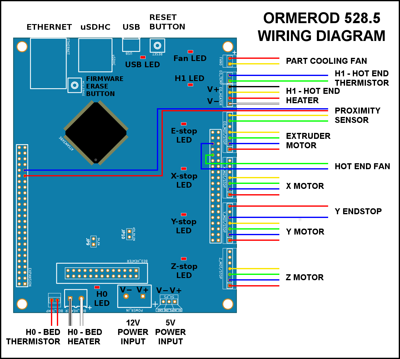
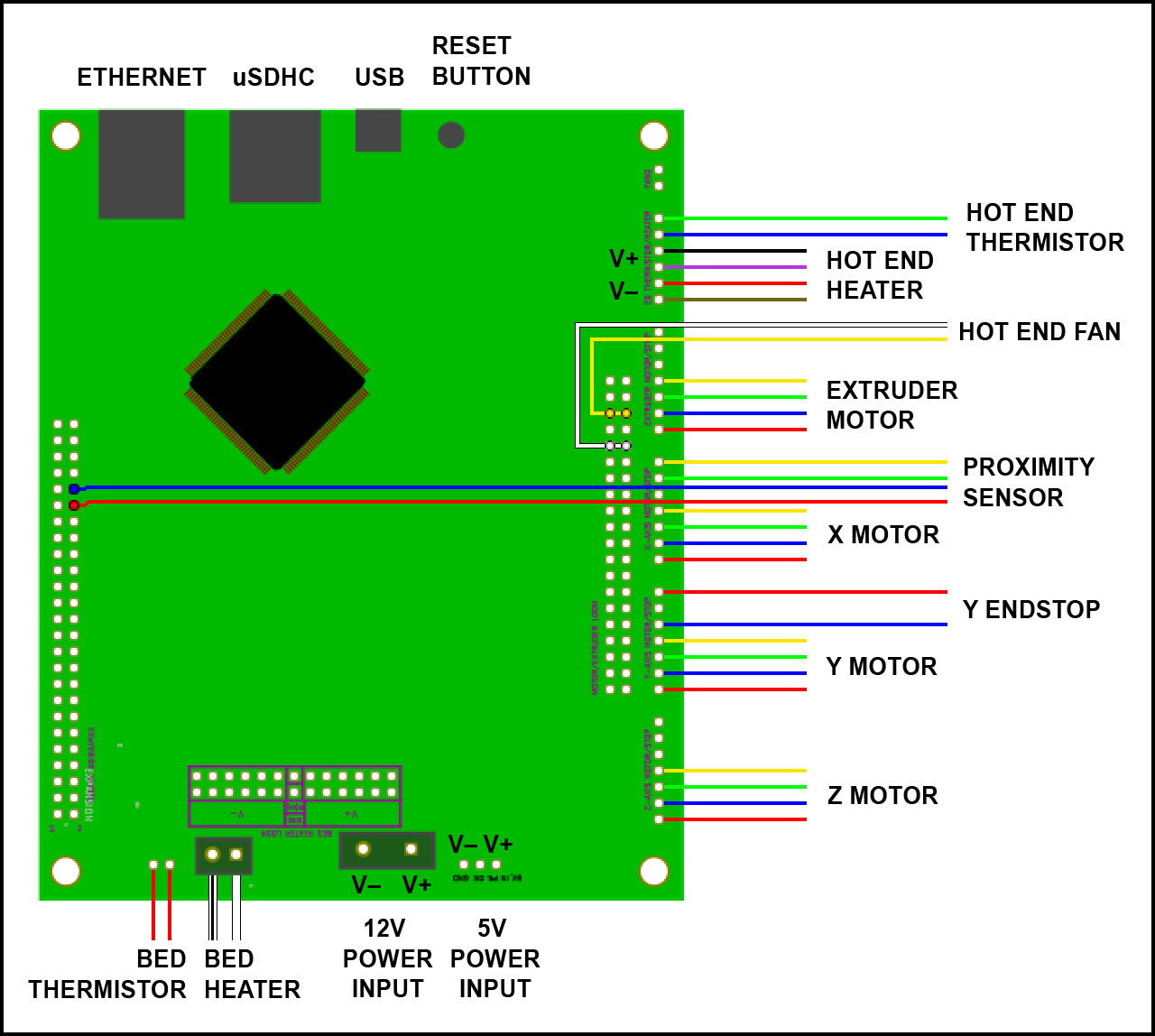
Wiring diagram
The instructions below show the fitting of the wiring. If in doubt, refer to this wiring diagram.
Fitting the wiring looms
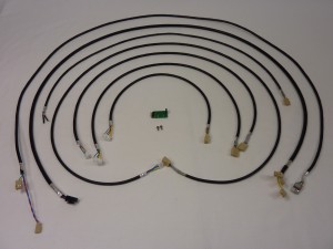
RepRapPro Ormerod 3D printer kits are supplied with pre-assembled wiring looms.
| # |
Component |
Qty |
Type |
| 589 |
Motor wiring loom – 410mm (Z) |
1 |
Wiring |
| 588 |
Motor wiring loom – 570mm (Y) |
1 |
Wiring |
| 587 |
Motor Wiring loom – 700mm (X) |
1 |
Wiring |
| 586 |
Motor wiring loom – 1100mm (E) |
1 |
Wiring |
| 552 |
End stop loom – 665mm |
1 |
Wiring |
| 1034 |
Hot end loom – 1190mm |
1 |
Wiring |
| 1033 |
Dual fan loom – 1190mm |
1 |
Hot end |
| 584 |
Proximity sensor loom 1340mm |
1 |
Wiring |
| 545 |
Proximity sensor PCB |
1 |
Electronics |
| 110 |
M2.5x5mm cap head screw |
2 |
Fasteners |
| 285 |
2-way PCB jumper (not shown) |
1 |
Electronics |
| 285 |
Cable tie 2mm |
as needed |
Hardware |
|
 |
| # |
Component |
Qty |
Type |
| 589 |
Motor wiring loom – 410mm (Z) |
1 |
Wiring |
| 588 |
Motor wiring loom – 570mm (Y) |
1 |
Wiring |
| 587 |
Motor Wiring loom – 700mm (X) |
1 |
Wiring |
| 586 |
Motor wiring loom – 1100mm (E) |
1 |
Wiring |
| 552 |
End stop loom – 665mm |
1 |
Wiring |
| 585 |
Hot end loom – 1190mm |
1 |
Wiring |
| 584 |
Proximity sensor loom – 1340mm |
1 |
Wiring |
| 545 |
Proximity sensor PCB |
1 |
Electronics |
| 110 |
M2.5x5mm cap head screw |
2 |
Fasteners |
| 285 |
2-way PCB jumper (not shown) |
1 |
Electronics |
| 285 |
Cable tie 2mm |
as needed |
Hardware |
|
|
Heated bed wiring
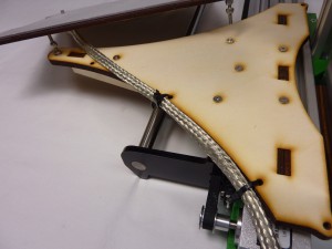
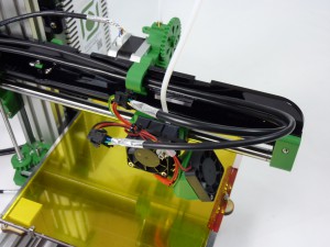
| If you have not done so already, use two cable ties to loosely attach the heated bed wiring to the edge of the y-carriage. This is important; it stops the hot end cable moving at the connections. The cable will bend along it’s length as the y-carriage moves, not at one point. You can do this without removing the heated bed. |
 |
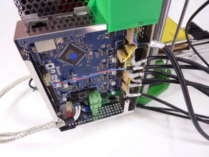
| The heated bed wiring connects to the screw terminal in the left-hand bottom corner of the Duet. Make sure the screw gates are open before putting the pre-crimped wires into the screw terminals, then tighten firmly. The heated bed doesn’t have any polarity; it doesn’t matter which way around they go. The thermistor wire plugs into the pins next to the screw terminal. Again, it has no polarity, it can plug in either way around. If you have a Duet with keyed header pins, it will only go on one way around. |
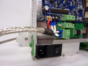 |
| Make sure there is plenty of room for the heated bed wire to move without kinking. (Ignore the y-motor wires, they are fitted in the next section.) |
 |
Motor wiring looms
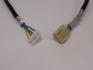
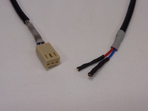
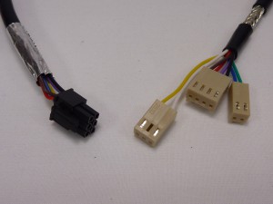
| Take the four motor looms. Each has connectors that look like this picture. Check the wiring order of the wires in the housings; if they have been assembled incorrectly, the motor will not run correctly. |
 |
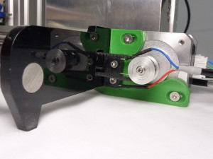
| The z-axis motor loom is the shortest. Connect the loom to the motor. |
 |
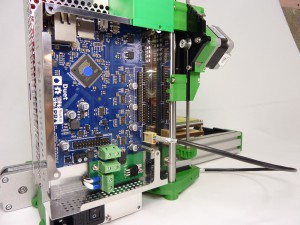
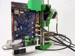
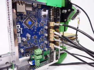
| The Z axis plugs in on the lowest pins on the Duet. We’ll be plugging in the motors, in order, from bottom to top. Each axis has 7 pins; 4 for the motor, three for the endstop (when needed). Check with the wiring diagram at the top of the page the orientation of the motor wire, and the exact pins it plugs into. |
 |
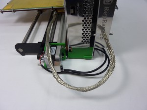
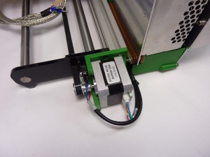
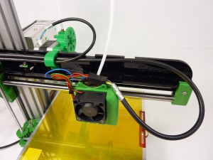
| The next shortest motor wiring loom is for the y-axis motor. Connect it to the motor and run it between the PSU and the Y axis aluminium extrusion. |
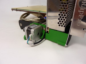 |
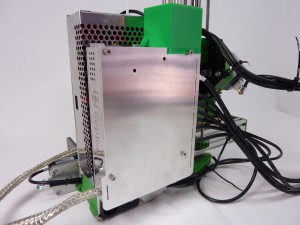
| If you have the newer PSU (528.2), there is a small gap in the side cover. Remove the side cover, run the Y motor wires through the PSU assembly. Leave the side cover off for the moment, as you will run the Y endstop wires through the same way, in a minute. |
 |
| It connects to the Duet on the next set of pins, above the z-axis. Again, check with the wiring diagram above to get the correct pins. There are labels for each axis, marked on the Duet. |
 |
| The x-axis motor loom is the next shortest. |
 |
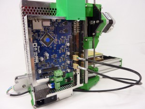
| Connect it to the set of pins above the y-axis. |
 |
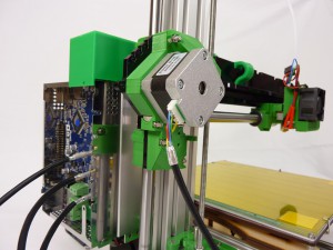
| The extruder motor loom is the longest motor loom. You can run the wire through the hook of the extruder motor, and back along the x-axis. |
 |
| It connects to the next set of pins up from the x-axis. |
 |
Y-endstop loom
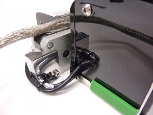
| The y-endstop loom is a two-wire loom. The two crimps that connect to the microswitch may be uncovered; if so, put heatshrink on them, as shown. |
 |
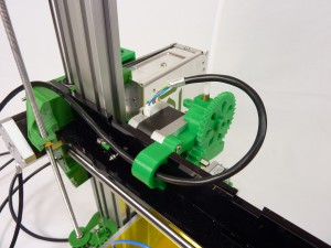
| The loom connects to the outer two pins of the microswitch, around the Y axis belt pulley. You will need to bend the top pin upwards to 45 degrees, so the wire doesn’t foul the pulley. |
 |
| Run it behind the PSU, as with the y-axis motor loom. |
 |
| If you have the newer PSU (528.2), there is a small gap in the side cover. Remove the side cover (if you haven’t already when fitting the Y motor loom), and run the Y endstop wires through the PSU assembly. Replace the side cover, with the Y motor and Y endstop looms coming through the gap. |
|
| We only use a microswitch endstop for the y-axis; the x- and z- axis use the proximity sensor to sense where the end of the axis is (the ‘home’ position). Connect it to the pins next to the y-axis motor. |
 |
Hot end and fan loom
Pay particular attention when connecting the hot end heater and hot end thermistor connectors. If you put them in the wrong place, 12V can run down the 3.3V line of the thermistor, and will immediately destroy the main processor chip. We regard this mistake as a user error, and is NOT covered by the warranty.
Ormerod 528.5 has two looms; one for the hot end (heater and thermistor), and one for the fans (hot end fan and part cooling fan).
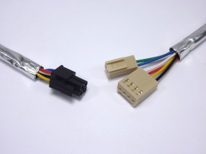
| The hot end loom is a 6-wire loom, with two different connectors on the end that connect to the Duet. The plug that connects to the hot end is 4-way; the hot end heater uses two pairs of wires, to carry the current the heater requires. The thermistor uses the other two wires. |
 |
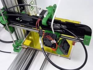
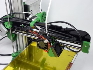
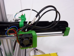
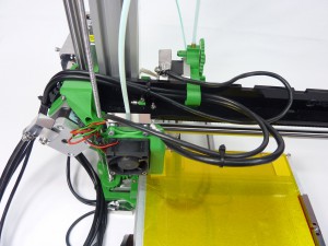
| Plug the hot end loom into the hot end connector. Loop it back along the x-axis arm, and through the hook in the extruder drive. |
 |
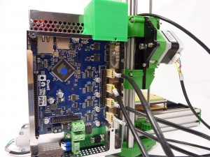
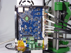
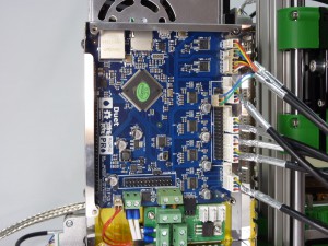
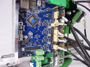
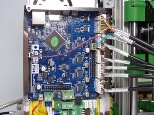
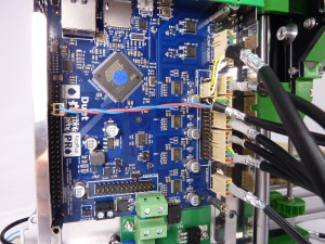
| Connect the hot end loom to the Duet. Pay close attention when connecting the hot end loom to the Duet. The thermistor wires (blue/green, 2-way) connects to the 2-pin ‘E0_TEMP’ header. The heater wires (black/yellow/red/white, 4-way) connect to the 4-pin ‘E0_HEATER’ header. DO NOT connect these to the ‘FAN0’ pins, at the top right of the Duet board. Check your wiring carefully with the wiring diagram. |
 |
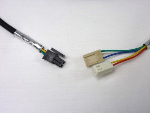
| The fan loom is a 4-wire loom, with two different connectors on the end that connects to the Duet. The plug that connects to the hot end is 4-way; two for each of the hot end fan and the part cooling fan. |
 |
| Connect the fan loom to the hot end and part cooling fans’ plug. Loop it back along the x-axis arm, and through the hook in the extruder drive, as you did with the hot end loom. |
 |
| The part cooling fan (red/yellow, 2-way) plugs into the 2-pin ‘FAN0’ header. This is controlled by gcode, and turns on during a print. The hot end fan (blue/none/green, 3-way) connects to the double row of pins, to provide it with 12V pins all of the time; see picture for correct placement. From the left, there should be two clear pins, then the yellow wire, another pin (covered by the housing, but not connected), then the white wire. Check your wiring carefully with the wiring diagram. |
 |
| The hot end loom is an 8-wire loom, with a number of different connectors on the end that connects to the Duet. The plug that connects to the hot end is 6-way; the hot end heater uses two pairs of wires, to carry the current the heater requires. The thermistor uses two wires, as does the hot end fan. |
 |
| Plug it into the hot end connector. Loop it back along the x-axis arm, and through the hook in the extruder drive. |
 |
| Pay close attention when connecting the hot end loom to the Duet. DO NOT connect anything to the ‘FAN0’ pins, at the top right of the Duet board; this is for any additional, controllable fan you may choose to fit, and it is NOT for the hot end fan. The hot end fan connects directly to the 12V pins, on the separate double row of pins; see picture for correct placement. Check your wiring carefully with the wiring diagram. |
 |
Proximity sensor and loom
Take care with the extruder motor and proximity sensor connections. It is possible to incorrectly connect these, and short the extruder motor voltage through the proximity sensor connection, potentially damaging the Duet.
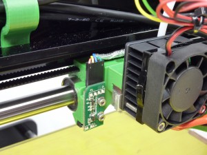
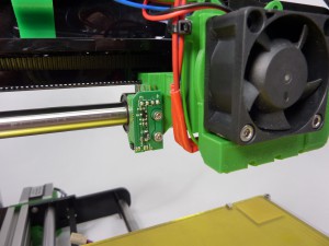
| The proximity sensor is a small PCB, with four pins on the end of the board. Make sure the sensor itself, the black part at the other end from the pins, is standing perpendicular to the board; they can get bent over in transit. |
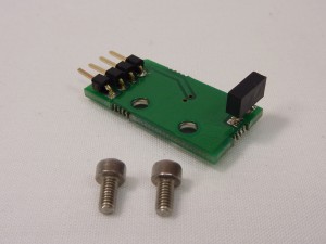 |
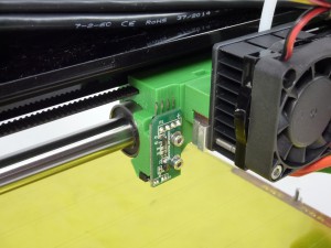
| Attach the proximity sensor to the X carriage to the left of the hot end with the two M2.5x5mm cap head screws. These self-tap into the X carriage, so don’t enlarge the holes with a drill. |
 |
| The proximity sensor wiring is the longest wiring loom. It has four wires, with the Duet end having two wiring blocks. |
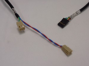 |
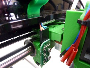
| Connect the loom. The wire can tuck backwards under the x-rib. NOTE: the sensor has a polarity; the order of the wires is very important. It should be as the picture, from left to right: red, yellow, blue, green. |
 |
| The proximity wiring loom can follow the hot end wiring loom; it needs a loop, to allow the x-carriage to move back and forth along the axis, then back along the x-axis arm, and through the hook in the extruder drive. |
 |
| The short end of the proximity sensor wire connects to the Duet board next to the extruder motor. The long part goes across the board to the other side, and connects to two pins on the ‘expansion’ header. It is important to get the orientation correct; check the wiring diagram. |
 |
| The proximity sensor is a small PCB, with four pins on the end of the board. Make sure the sensor itself, the black part at the other end from the pins, is standing perpendicular to the board; they can get bent over in transit. |
|
| Attach the proximity sensor to the X carriage to the left of the hot end with the two M2.5x5mm cap head screws. These self-tap into the X carriage, so don’t enlarge the holes with a drill. |
 |
| The proximity sensor wiring is the longest wiring loom. It has four wires, with the Duet end having two wiring blocks. |
|
| Connect the loom. The wire can tuck backwards under the x-rib. NOTE: the sensor has a polarity; the order of the wires is very important. It should be as the picture, from left to right: red, yellow, blue, green. |
 |
| The proximity wiring loom can follow the hot end wiring loom; it needs a loop, to allow the x-carriage to move back and forth along the axis, then back along the x-axis arm, and through the hook in the extruder drive. |
 |
The proximity sensor loom has two connectors. The short wires plug in to a free endstop connection. You can use either the X endstop pins (above the X motor connection), or the extruder endstop pins (above the extruder motor connection), depending on where the gap in metal perimeter is. There have been a couple of different versions of the perimeter; the current version uses the extruder endstop pins (as shown in the picture), older versions use the X endstop pins.
The longer wires reach across the board, and plug into two pins in the expansion header. Check the wiring diagram at the top of the page to see exactly which pins. |
 |
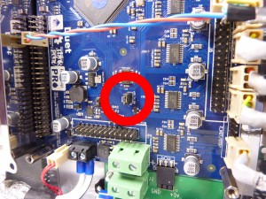
IMPORTANT: 5V JUMPER!
| Fit the 2-way PCB jumper (a small, black, jumper block) on the two pins in the centre of the board, labelled ‘J10’ and ‘ATX_5V_EN’. Without this, the Duet board will not be supplied with power without the USB connected! |
 |
Fitting the cover and wire routing
You may want to do this section after the commissioning stage (the next page of the instructions), as it is useful to be able to access the Duet board, ie to press ‘reset’, or check your wiring, during commissioning.
| # |
Component |
Qty |
Type |
| 577 |
enclosure lid |
1 |
Sheet metal |
| 257 |
M3x12mm cap head screw |
4 |
Fastener |
|
PICTURE TO COME |
| All the wiring looms use shielded cable, to reduce the effects of Electro-Magnetic Interference (EMI). It is important that the shielding makes contact with ground, by earthing them through the metal case. Each wire has a slot in the case; bend each cable so it sits in the slot. Make sure that there is not sideways pressure on the housings, where they are plugged onto the pins of the Duet; they can loose their contact with the pin, and make a faulty connection. |
 |
| With all of the wires in their slots, attach the enclosure cover with 4 x M3x12mm cap head screws. There are a number of slots in the cover; make sure the tabs of the enclosure line up and can pass through. They can be quite tight. |
 |
| The wires on the x-axis need to be able to move up and down with the z-axis. They can be attached at the bottom of the Z axis, and cable tied there. |
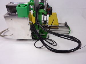 |
| Extruder and hot end. The wires clip under the extruder mounting bracket, and can be cable-tied to the x-axis arm. Make sure there is enough slack in the hot end wires to allow the x-carriage to move the full length of the x-axis. |
 |
| Make sure there is plenty of room for the heated bed wire to move without kinking. |
|
Spool mount
| # |
Component |
Qty |
Type |
| 642 |
spool plate |
1 |
Lasercut |
| 641 |
spacer |
1 |
Lasercut |
| 442 |
spool-spigot |
1 |
Printed |
| 525 |
spool-clip |
1 |
Printed |
| 424 |
M4x16mm button head screw |
3 |
Fastener |
| 497 |
M4 T-nut |
3 |
Fastener |
| 241 |
M3x20mm cap head screw |
1 |
Fastener |
| 258 |
M3 nut |
1 |
Fastener |
| 190 |
PTFE tube 3mm OD x 400mm |
1 |
Wiring |
|
 |
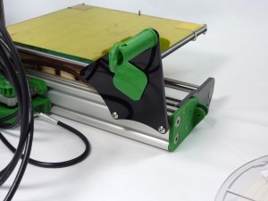
| Loosely attach the spacer to the spool plate with 3 x M4x16mm button head screws, with the 3 x T-nuts. |
 |
| The spool-spigot attaches to the top of the spool plate. Drop the M3 nut down the spool-spigot, and screw the M3x20mm cap head screw in from the other side. This can be fiddly; you can always do it the other way around, with the M3x20mm cap head screw going into the spool-spigot, and the nut on the outside. |
 |
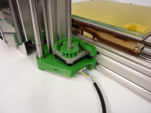
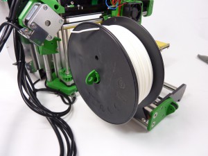
| Attach the spool mount to the y-axis extrusion, as shown. |
 |
| The spool mounts on the spigot, and the spool-clip holds it in place. |
 |
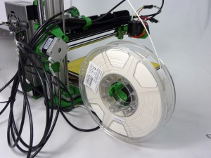
| You can adjust the position of the spool mount to accommodate larger spools. Unfortunately, there is no standard in spool size, so it may not be able to accommodate all spools! Use just two of the M4x16mm button head screws, and locate them in the top slot of the Y axis extrusion. This will lift the spigot up and away from the Z axis. |
 |
| The spool mounts in the same way as before. |
 |
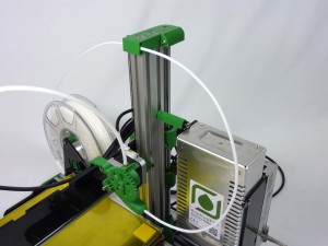
| Finally, fit the filament guide tube. This will allow filament to be fed into the extruder drive. There are three holes in the Z axis upper mount (Ormerod 528.5 version). Feed one end of the tube into this, and the other end into the extruder drive. Filament is then fed into the Z upper mount, through the tube, and into the extruder drive. If you feed filament directly into the drive, without using the tube, filament may pull on the X axis as it is drawn into the extruder, causing the X axis to wobble in the Y axis direction. |
 |
Fitting the shielding
For CE compliance, shields need to be fitted to the hot end, motor and heated bed connections. Again, it may be better to fit these shields, if required, after the commissioning stage, as you may need access to the motor wiring.
| # |
Component |
Qty |
Type |
| 582 |
Motor Shield |
3 |
Shielding |
| 579.1 |
Motor Shield (Z axis) |
1 |
Shielding |
| 891 |
Hot end enclosure (not shown) |
1 |
Shielding |
| 575 |
Bed cable shield (not shown) |
1 |
Shielding |
| 543 |
M3x30mm cap head screw |
3 |
Fastener |
| 713 |
M3x30mm countersunk screw |
1 |
Fastener |
| 133 |
Cable tie 2mm |
4 |
Fastener |
|
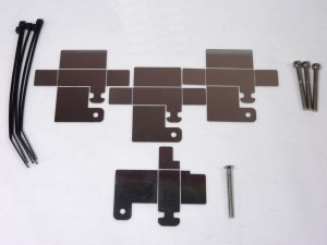 |
Note the z-motor-shield is different from the other three.
| # |
Component |
Qty |
Type |
| 644 |
motor-shield |
3 |
Shielding |
| 579 |
z-motor-shield |
1 |
Shielding |
| 580 |
hotend-shield |
1 |
Shielding |
| 575 |
heated-bed-shield |
1 |
Shielding |
| 543 |
M3x30mm cap head screw |
3 |
Fastener |
| 257 |
M3x12mm cap head screw |
3 |
Fastener |
| 241 |
M3x20mm cap head screw |
2 |
Fastener |
| 713 |
M3x30 countersunk screw |
1 |
Fastener |
| 258 |
M3 nut |
5 |
Fastener |
|
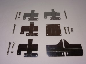 |
Note the z-motor-shield is different from the other three; it has an extra notch in it.
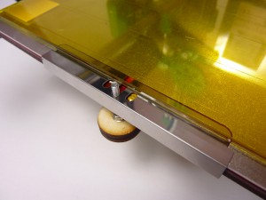
Heated bed shield
| The heated bed shield covers the connections on the heated bed. |
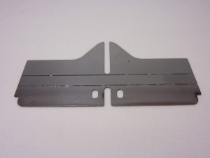 |
| Fold it as shown. The bends are not quite 90 degrees. |
 |
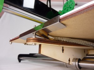
| The top tab of the bed shield slides under the glass, but is supported at the sides by the aluminium heat spreader. It is designed so it should not touch the heated bed terminals. |
 |
| Underneath, it touches the shielding of the heated bed wiring loom. |
 |
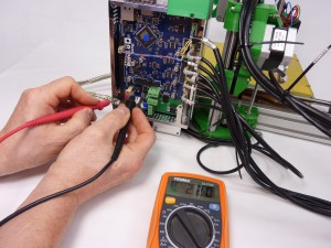
| Check there is no continuity between the shielding and the bed +12V and ground screw terminals. |
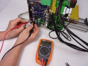 |
| Make sure you check both! |
 |
| If you have any problems, cover the heated bed connections with Kapton tape. This is a very effective insulator – it was designed by NASA! |
 |
Hot end enclosure
X motor shield
Y motor shield
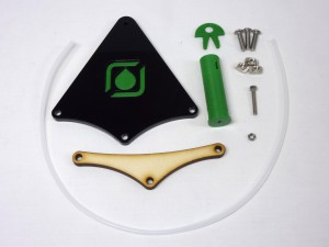
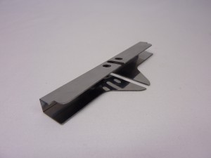
Z motor shield
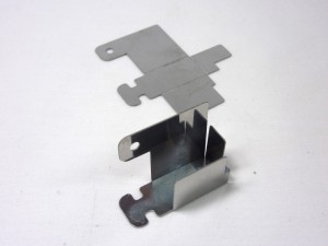
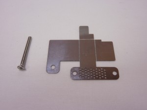
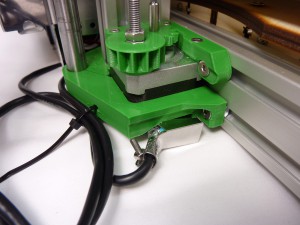
| Fold the shield as shown. This shield is different from the other three; the wiring loom path is straight, and there is a notch in the shield to fit around the Z lower mount. |
 |
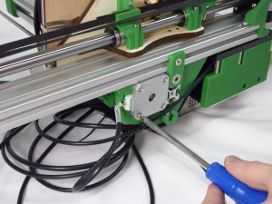
| Remove the crosshead screw from the corner of the motor. Fit the shield in place using an M3x30mm countersunk screw. |
 |
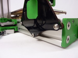
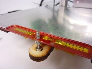
| Secure the motor loom to the shield with a cable tie, as shown. Make sure the shield does not stick out below the foot of the Z lower mount, or the printer will not sit flat. |
 |
| The z-motor-shield is different from the other motor shields; it has an extra notch in it. It uses an M3x30mm countersunk screw, a M3x10mm cap head screw (not shown), and an M3 nut (not shown). |
 |
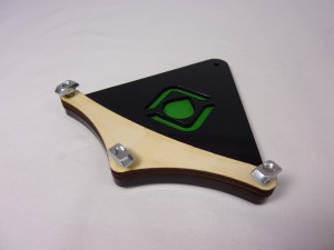
| Fold the z-motor-shield as shown. |
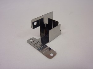 |
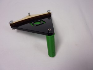
| The z-motor-shield is quite tricky to fit, to make sure that the printer does not rest on it. Remove the motor screw, and attach the shield. It should slide in around the motor connector, between the printed part. |
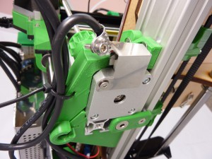 |
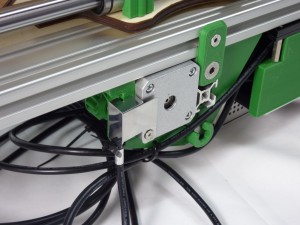
| Another view of the connector. |
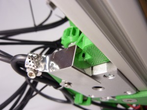 |
| Fold the cable clamp over the end of the wire, so it holds the exposed shielding of the cable, and secure with the M3x10mm cap head screw and M3 nut. |
 |
Extruder motor shield