Which hot end?
All Ormerod 2 528.5 and onwards kits ship with the new ‘Quick-set’ nozzle. This page has the instructions for that nozzle.
| This is the Quick-set nozzle, supplied with Ormerod 2 528.5 and onward kits. If your nozzle looks like this, please use the instructions on this page. |
 |
| This is the one-piece stainless steel nozzle. If you nozzle looks like this, please use the instructions on the ‘Hot end assembly‘ page. |
 |
Building the hot end
Assembling the hot end parts
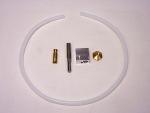
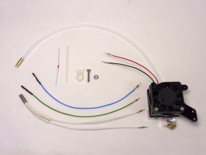
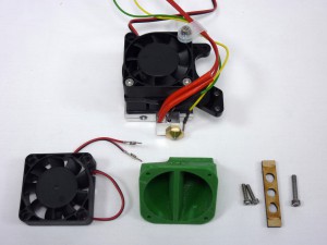
| All the parts for the hot end, like the extruder, come in one bag. |
 |
The Bowden tube and nozzle
The Bowden tube guides the filament from the extruder to the hot end, where the filament is melted and extruded through the nozzle.
| # |
Component |
Qty |
Type |
| 1055 |
4mm PTFE Bowden tube |
1 |
Hot end |
| 106.1 |
Brass Bowden start |
1 |
Hot end |
| 738 |
Quick-set nozzle (0.5mm) |
1 |
Hot end |
| 739 |
Quick-set heater block |
1 |
Hot end |
| 794 |
Quick-set Tapered brass M4 nut |
1 |
Hot end |
|
 |
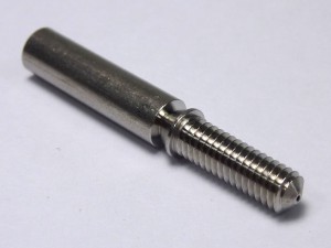
| Start by building the hot end. Take the nozzle, aluminium heater block and tapered brass nut. Screw the heater block onto the nozzle, as tight as you can, but with fingers only. If you use pliers to hold the nozzle, and a spanner on the heater block, you may break the nozzle at it’s thinnest part! Note the small hole in the heater block is towards the tip of the nozzle. |
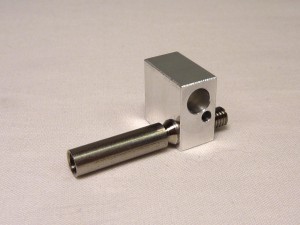 |
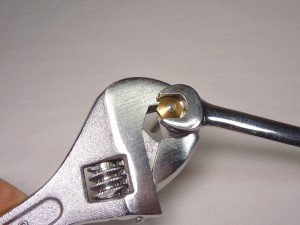
| Holding the heater block in a 14mm spanner (or an adjustable spanner), screw on the tapered brass nut. Tighten the tapered brass nut against the heater block, with a 10mm spanner. This DOES need to be done up tight; the heater block and tapered brass nut lock together, tight on the thread of the nozzle, to ensure good heat transfer from the heater block into the nozzle. The heater block may unscrew a fraction on the nozzle as you do this, but that’s okay. |
 |
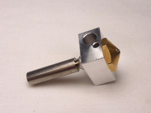
| The cone of the nozzle should continue the cone of the nut, or as close as possible. There shouldn’t be a shoulder between the two, nor should the nozzle be down inside the nut. |
 |
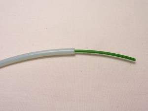
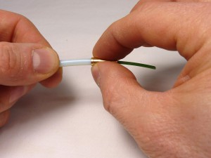
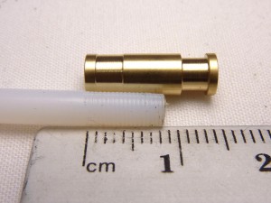
| Take the PTFE tube. Make sure the ends of the PTFE tube are cut square. (Filament has been inserted into tube just to show the tube against the background.) |
 |
| You are going to screw the brass Bowden start and the nozzle onto each end of the tube. This will compress the PTFE tube’s inner hole. To allow the filament to run freely in the tube, you need to open out the ends of the PTFE tube first. Use a 2.5mm (2mm is too small, 3mm is too big) drill bit in a small hand chuck, or a slow electric drill. |
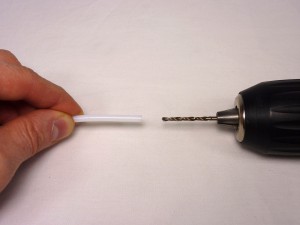 |
| Gently, and twisting clockwise all the time – never anti-clockwise, whether going in or coming out – use the drill bit to enlarge the inner hole in the PTFE, to a depth of around 15mm. Try to keep the drill as straight as possible into the tube. |
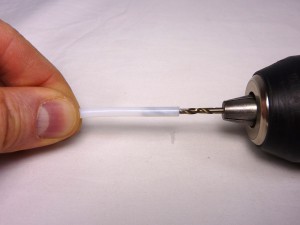 |
| Take several goes at it, going a couple of millimetres deeper each time and drawing the PTFE swarf out by keeping twisting clockwise and pulling. The drill should pull the PTFE swarf out with it. Repeat the process at the other end of the PTFE tube. |
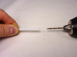 |
| IMPORTANT! The PTFE tube MUST BE CLEAR OF ALL PTFE SWARF before screwing the nozzle on! Push a piece of filament (use the 50cm piece you cut for the extruder testing) through the tube, which should push out any remaining PTFE swarf. Blow down the tube, from both ends, as well. It is very important to get any PTFE swarf out of the tube, otherwise this will end up in the nozzle the first time you print, blocking it! |
 |
| Now you’re going to screw the brass Bowden end and the nozzle onto the PTFE tube. To help guide them onto the tube straight, put a piece of filament into the PTFE tube. This will keep the brass Bowden end (and nozzle) and PTFE tube axially in line; you don’t want them screwed on at an angle. Push the brass Bowden end up to the PTFE tube, and push while turning it clockwise. It will start to cut its own thread into the PTFE tube. |
 |
| If you have difficulty gripping the brass Bowden end, you can use the nozzle instead. With the heater block on it, it is easier to turn. You will have to remove it afterwards, and put the brass Bowden end back on, but it will be much easier the second time. |
 |
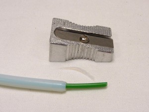
| If you have trouble getting the brass Bowden end started on tube, you can use a pencil sharpener to make a cone on the end of the tube. |
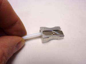 |
| Don’t cut too deeply with the pencil sharpener, which will make the cone too deep and long, or it will compress onto the filament when the brass Bowden end, or nozzle, are screwed on. |
 |
| Keep turning until the Bowden end will not screw on any further. If you then remove the brass union, you should see that the Bowden tube end has been threaded, to a depth of around 8mm. |
 |
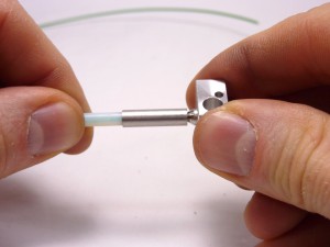
| Using the same process, put the nozzle on the other end of the PTFE tube. |
|
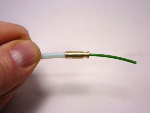
| Push a piece of filament through the tube, to check that it moves smoothly, with little or no friction. Check it goes all the way down into the nozzle. It should move nearly as freely as when the brass Bowden end and nozzle were not fitted. If the filament is sticking, you may be able to release it by unscrewing the brass Bowden end and/or nozzle one turn. |
 |
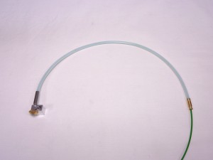
| The finished Bowden tube and nozzle. |
 |
The cooling system
It’s very important that the top of the nozzle remains cold; if filament melts too high up, the pressure required to extrude will increase, and the nozzle will block and stop extruding.
| # |
Component |
Qty |
Type |
|
Bowden tube and nozzle |
1 |
Assembled |
| 736 |
Quick-set cooling block |
1 |
Hot end |
| 357 |
Heatsink |
1 |
Hot end |
| 741 |
Quick-set hot end fan spacer |
1 |
Hot end |
|
Fan |
1 |
Hot end |
| 520 |
M3x35mm cap head screw |
2 |
Hot end |
| Fan is 12V (#953) for Ormerod/Mendel, 19V (#846) for Huxley |
|
 |
| Take the fan, and push the two M3x35mm cap head screws through the holes in the fan furthest from the fan wire. |
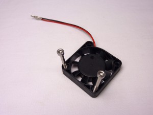 |
| Remove any protective film from the acrylic fan spacer. |
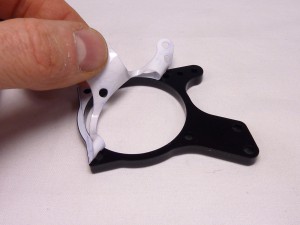 |
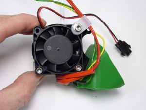
| Place the fan on the fan spacer. Orient the fan spacer as shown. The sticking out part of the fan spacer is used to mount the proximity probe, which sets the nozzle height from the bed, and can automatically compensate for the bed level. |
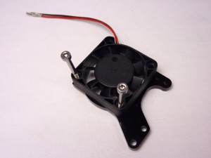 |
| The heatsink goes on next, behind the fan spacer. It only has two holes in it; make sure the M3x35mm cap head screws go through. The fins of the heatsink should face the fan; the solid part is to the back. |
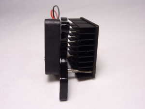 |
| Next is the aluminium cooling block. The orientation of this is critical. The heatsink mounting holes are off-centre; orient the block so the holes are closest to the bottom. The long side of the aluminium cooling block will be in contact with the heatsink. |
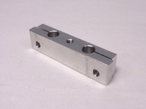 |
| The cooling block mounting holes are only threaded on one side of the block; the cooling block also clamps the hot end in place. The threaded part should be AWAY from the heatsink. The M3x35mm cap head screws will push through the first half of the cooling block, before engaging the thread. |
 |
| Push the two M3x35mm cap head screws through the four parts, and lightly screw it into the aluminium cooling block. Don’t tighten this up yet; it needs to clamp the nozzle in place. The bottom edge of the heatsink should line up with the bottom edge of the aluminium cooling block, and the solid part of the heatsink should be in good contact with the cooling block. |
 |
| Now mount the Bowden tube and nozzle. Thread the slotted brass Bowden end up through the aluminium cooling block, followed by the Bowden tube, and then thread the nozzle into cooling block. |
 |
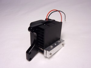
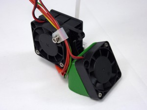
| The hot end should be aligned with the bottom of the cooling block as shown, with the ‘neck’ of the nozzle just below the cooling block. Orient the heater block so it is under the heatsink and fan, rather than sticking out the back. Tighten the M3x35mm cap head screws, to sufficiently clamp the nozzle in place and pull the heatsink onto the aluminium cooling block, but do not over-tighten them – you will break the fan. |
 |
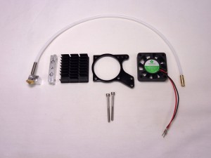
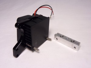
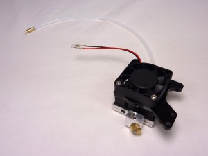
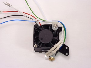
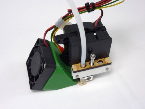
| The hot end assembly so far. |
 |
Wiring the hot end
Thermistor wires
Older kits have the thermistor wiring pre-made. We changed the crimp on the current kits to improve the grip on the thermistor wire, but you’ll need to do the following.
| # |
Component |
Qty |
Type |
| 433 |
Thermistor wiring – 160mm |
2 |
Hot end |
| 197 |
2.4mm Black heatshrink |
as needed |
Hot end |
|
New picture to come |
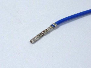
| If your thermistor wiring is supplied without heatshrink on both ends, and the female end looks like this, do the following. |
 |
| Fold in the two barbs that stick out the side, as shown in the first picture; a small screwdriver or tool with a point is easiest. They need to fold into the crimp, as they will hold the thermistor wire. |
 |
| Also flatten the top two tabs, so the crimp is smooth. If you put the heatshrink on with them sticking up, they can cut through the heatshrink, and cause a short circuit if they touch other metal. |
 |
| Put the heatshrink on the end of the wire, covering the crimp but leaving the end open. |
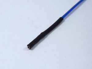 |
| Check that it holds the thermistor firmly. You will cover the thermistor with high temperature PTFE heatshrink in the next step; you want as little metal showing as possible between the PTFE heatshrink and the black heatshrink, to avoid short circuits to metal parts of the printer. |
 |
Heater block wiring
The heater block heats the nozzle up to the melting point of the plastic filament, typically around 200C.
| # |
Component |
Qty |
Type |
|
Hot end assembly |
1 |
Assembled |
| 430 |
100K thermistor |
1 |
Hot end |
| 167 |
Transparent PTFE heatshrink |
about 50mm |
Hot end |
| 841 |
3mm P-clip |
1 |
Hot end |
| 242 |
M3x16mm cap head screw |
1 |
Hot end |
| 212 |
M3 plain washer |
1 |
Hot end |
| 433 |
Thermistor wiring – 160mm |
2 |
Hot end |
| 445 |
Cartridge heater (red wires) |
1 |
Hot end |
|
New picture |
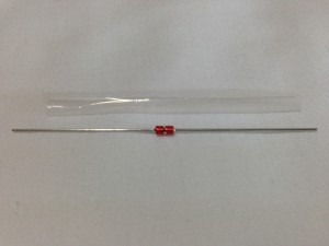
| Cut the transparent PTFE heatshrink about 8mm shorter than the thermistor with its axial connecting wires. Put the thermistor in it so that 4mm of wire protrudes from each end. |
 |
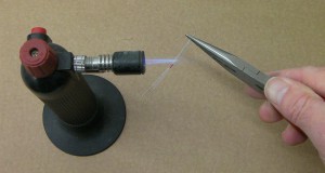
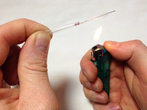
| Using a flame (a cigarette lighter, blowtorch, gas hob, or hot air gun work well; a hair dryer does not), shrink the heatshrink over the thermistor. Just waft the thermistor and heatshrink through the flame. You don’t want the heatshrink to overheat and to burn. |
 |
| If you’re doing this with a cigarette lighter, hold the thermistor at one end, and heat the heatshrink from the middle out to the other end. The heatshrink will be transparent when it has fully shrunk, and will then go back to opaque when the heat is removed. Keep it above, not in, the flame, so it doesn’t overheat and go black. |
 |
| Let it cool for a few moments, then turn it around and do the other side. Rolling the thermistor between your fingers while heating will improve the consistency of the heatshink. |
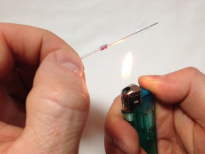 |
| Turn it around again and heat the first side, rolling it in your fingers, to get a really good, even heatshrink. Make sure it has shrunk properly around the central bulge, or it won’t fit easily into the heater block. |
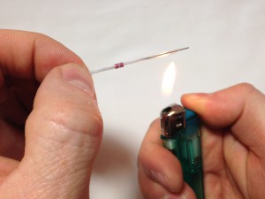 |
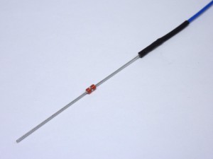
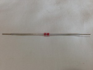
| This is how the thermistor should look with the PTFE shrunk onto it. |
 |
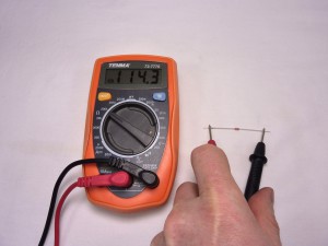
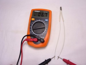
| Test the resistance of the thermistor with a multimeter. It should be around 100k ohms at an ambient temperature of 25C. Like the heated bed thermistor, the resistance will be greater if it is colder, and less if hotter. |
 |
| Check the resistance of the heater cartridge. It should be around 3.0 ohms. |
New picture |
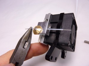
| Pull the thermistor through the small hole in the heater block so that it is about half way through. If you pull it with pliers, be gentle, and grip on the PTFE heatshrink, not the bare wire. If it doesn’t want to go through, try reheating the heatshrink, for a tighter fit. |
 |
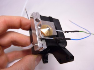
| To stop the thermistor falling out, turn the thermistor wire around the back of the heater block as shown. This also means that all the wires go up one side of the hot end. Attach the thermistor wires. |
 |
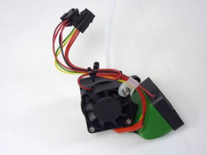
| Push the heater cartridge into the heater block. Bend the wires up the side of the heatsink duct. Secure the cables into the p-clip and attach it loosely to the laser cut fan spacer using an M3x16mm cap head screw and M3 washer. We will be adding a shielding part to this later, when we connect the loom. |
New picture |
| # |
Component |
Qty |
Type |
|
Hot end assembly |
1 |
Assembled |
| 430 |
100K thermistor |
1 |
Hot end |
| 167 |
Transparent PTFE heatshrink |
about 50mm |
Hot end |
| 841 |
3mm P-clip |
1 |
Hot end |
| 242 |
M3x16mm cap head screw |
1 |
Hot end |
| 212 |
M3 plain washer |
1 |
Hot end |
| 433 |
Thermistor wiring – 160mm |
2 |
Hot end |
| 662 |
Cartridge heater (white wires) |
1 |
Hot end |
|
 |
| Cut the transparent PTFE heatshrink about 8mm shorter than the thermistor with its axial connecting wires. Put the thermistor in it so that 4mm of wire protrudes from each end. |
|
| Using a flame (a cigarette lighter, blowtorch, gas hob, or hot air gun work well; a hair dryer does not), shrink the heatshrink over the thermistor. Just waft the thermistor and heatshrink through the flame. You don’t want the heatshrink to overheat and to burn. |
|
| If you’re doing this with a cigarette lighter, hold the thermistor at one end, and heat the heatshrink from the middle out to the other end. The heatshrink will be transparent when it has fully shrunk, and will then go back to opaque when the heat is removed. Keep it above, not in, the flame, so it doesn’t overheat and go black. |
|
| Let it cool for a few moments, then turn it around and do the other side. Rolling the thermistor between your fingers while heating will improve the consistency of the heatshink. |
|
| Turn it around again and heat the first side, rolling it in your fingers, to get a really good, even heatshrink. Make sure it has shrunk properly around the central bulge, or it won’t fit easily into the heater block. |
|
| This is how the thermistor should look with the PTFE shrunk onto it. |
|
| Test the resistance of the thermistor with a multimeter. It should be around 100k ohms at an ambient temperature of 25C. Like the heated bed thermistor, the resistance will be greater if it is colder, and less if hotter. |
|
| Check the resistance of the heater cartridge. It should be around 6.8 ohms. |
 |
| Pull the thermistor through the small hole in the heater block so that it is about half way through. If you pull it with pliers, be gentle, and grip on the PTFE heatshrink, not the bare wire. If it doesn’t want to go through, try reheating the heatshrink, for a tighter fit. |
|
| To stop the thermistor falling out, turn the thermistor wire around the back of the heater block as shown. This also means that all the wires go up one side of the hot end. Attach the thermistor wires. |
|
| Push the heater cartridge into the heater block. Bend the wires up the side of the heatsink duct. Secure the cables into the p-clip and attach it loosely to the laser cut fan spacer using an M3x16mm cap head screw and M3 washer. We will be adding a shielding part to this later, when we connect the loom. |
 |
Wiring the hot end connector
| # |
Component |
Qty |
Type |
|
Hot end assembly |
1 |
Assembled |
| 847 |
2×2 female black crimp socket |
2 |
Hot end |
|
Picture to come |
CAUTION! The next step describes wiring up the hot end connector. GREAT CARE should be taken doing this. The heater cartridge and the fan wires have 12V running through them ALL THE TIME. The thermistor wires are 3.3V, and connect directly to the Arduino chip on the Duet. If you incorrectly wire the plug, a short circuit between the thermistor wires and any of the other wires MAY DESTROY YOUR DUET!
Wiring diagram
Note: the ‘cooling fan’ wiring is not connected until the hot end is mounted on the printer.
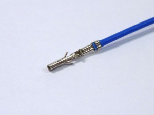
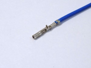
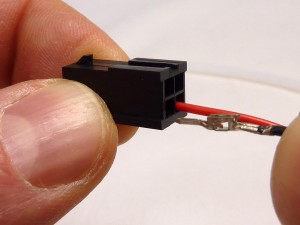
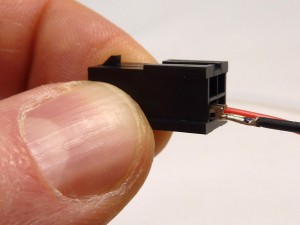
| Put the pins on the ends of the hot end wires into the four-way female sockets. The wiring diagrams, above, are looking into the back of the socket, where you insert the crimps. The little black rectangle is the locking tab, and the housing has small embossed ‘1’ and ‘4’ numbers on it, so you can orientate it as the diagram. The pins are crimped on one side, and smooth on the other. The smooth sides go downwards in the diagram. |
 |
| Neither the thermistor nor the heater cartridge have a polarity so it doesn’t matter which way round their wires go. (Though the labels are the way that the machine will apply power.) Make sure to get the polarity of the fans right. These pictures show one of the hot end fan wires being put into the housing, but it is not fully in yet; you can’t see the crimp easily when it is. |
 |
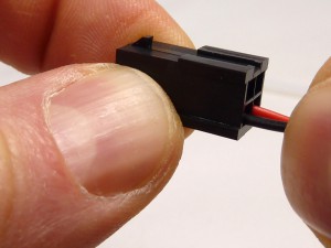
| Check that the pins are all the same depth into the housing. The pins are very difficult to remove without damaging them, so check twice, plug in once! They should click into place, and then shouldn’t easily push further through, or pull back out. |
 |
| If you need to remove the pins, the easiest way is with the correct tool. However, this is rather expensive! We usually find the crimps come out fairly easily if you use a pair of very fine, pointed tweezers. You need to clip these (or any other narrow, thin metal shim) up each side of the crimp, from the open end of the housing (not the end the wire goes into), to flatten the sprung tabs on the side of the crimp. You can see the tabs in the picture. Both hot end and loom sides are effectively the same. |
|
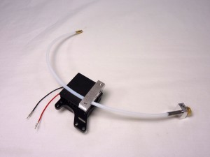
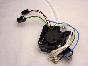
| The hot end with the wiring in place in the crimp housings. (Picture shows a Huxley heater cartridge, with white wires; Ormerod and Mendel 3 use a heater cartridge with red wires.) |
 |
Wire colours, related to hot end wiring loom
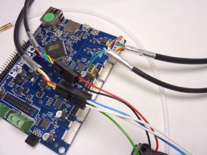
| You can check the wire order by comparing it to the hot end loom, which the hot end plugs into. |
 |
Fan wiring loom (4 wires)
| Fan wiring loom |
Fan wires |
| 1 Green (GND) |
Hot end fan BLACK wire |
| 2 Blue (+12V) |
Hot end fan RED wire |
| 3 Yellow (FAN GND) |
Cooling fan BLACK wire |
| 4 Red (FAN +12V) |
Cooling fan RED wire |
Note: the ‘cooling fan’ wiring is not connected until the hot end is mounted on the printer.
Hot end wiring loom (6 wires)
| Hot end wiring loom |
Hot end wires |
| 1 Green (3.3V) |
Thermistor wire (green/blue) |
| 2 Blue (3.3V) |
Thermistor wire (green/blue) |
| 3 Black (Hot end heater +19V) |
Thick red heater wire |
| 3 Yellow (Hot end heater +19V) |
| 4 Red (Hot end heater GND) |
Thick red heater wire |
| 4 White (Hot end heater GND) |
| Hot end wiring loom |
Hot end wires |
| 1 Green (3.3V) |
Thermistor wire (green/blue) |
| 2 Blue (3.3V) |
Thermistor wire (green/blue) |
| 3 Black (Hot end heater +19V) |
Thick white heater wire |
| 3 Yellow (Hot end heater +19V) (May be PURPLE) |
| 4 Red (Hot end heater GND) |
Thick white heater wire |
| 4 White (Hot end heater GND) (May be BROWN) |
NOTE: Some Huxley hot end wiring looms use different colours. The yellow wire is purple, and the white wire is brown. Apart from this, the wiring should be the same.
Final assembly and mounting
| # |
Component |
Qty |
Type |
|
Hot end assembly |
1 |
Assembled |
| 953 |
12V Fan |
1 |
Hot end |
| 1123 |
Cooling fan duct |
1 |
Hot end |
| 461 |
M2.5x10mm cap head screw |
2 |
Hot end |
| 160.1 |
MDF heat insulator |
1 |
Hot end |
| 242 |
M3x16mm cap head screw |
1 |
Hot end |
|
 |
| NOTE: You may want to connect the cooling fan and duct at a later point (i.e. once you have got the printer printing), as it requires the bed to be level first, and may, initially, get in the way.
The fan duct pushes onto the arm of the acrylic spacer. Make sure it is fully engaged, or it will be lower than the nozzle. |
 |
| Screw the 12V fan on to the duct with the M2.5x10mm cap head screws. |
 |
| Connect the cooling fan wires to the 2×2 female fan housing. See the wiring diagram above for correct position. |
 |
| Thread the MDF insulator onto the Bowden tube, and slide it down the tube until sits on top of the aluminium cooling block. Thread the M3x16mm screw through the MDF insulator and into the aluminium cooling block, as shown. Just put the screw in a couple of turns. |
 |
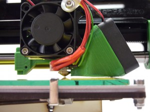
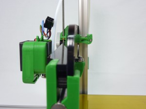
| The hot end mounts onto the x-carriage via the nozzle-mount. |
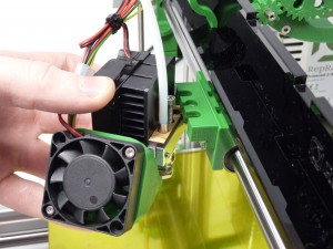 |
| It should push on sideways, and you can then fix it into place using the two screws. The MDF insulator should sit UNDER the nozzle mount, but on top of the aluminium cooling block, so it is sandwiched between them. |
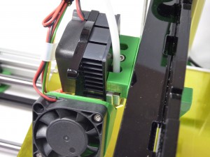 |
| The hot end should be mounted vertically. If the hot end is leaning forward, the fan duct may be lower than the nozzle. If it leans back, the proximity sensor may be lower. Check that it is seated correctly in the nozzle-mount. |
 |
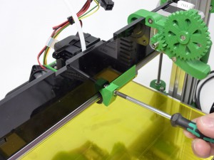
| The angle of the hot end can be changed, by adjusting the x-carriage idler bearing on the back of the x-axis-plate. It is mounted in a slot (this may need cleaning to allow the bolt to slide in it), so loosen it, hold the hot end where you want it, then push the bearing against the x-axis-plate and re-tighten. Check that the hot end is vertical. |
 |
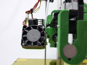
| Wind down the X axis by turning the Z leadscrew, until the nozzle is just above the bed. The nozzle should be a couple of millimetres lower than the fan duct. |
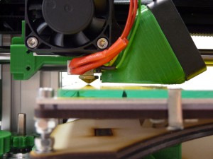 |
| The bed may not be level yet. Check if the nozzle is the same height at the other end of the X axis. If the nozzle isn’t lower than the fan duct, it’s possible that the nozzle is set too high in the aluminium cooling block. |
 |
| If the nozzle seems to drop, or rise and fall, as it moves along the X axis, check that the x-axis plate is straight, flat, and vertical along it’s length. Remove the extruder, and look along the back of the x-axis-plate. It can twist around the x axis smooth rod; twist it back vertical, and tighten the screw in the x-idler, and the screws in the x-motor-mount. |
 |
| A view along the back of the x-axis-plate, checking it is straight and flat. |
 |
| Finally, once printing, the nozzle may droop forward. This usually means that the cooling of the hot end has not been working correctly. Heat may have been getting through the screws and melting the nozzle-mount, which may distort it. Check the hot end construction, that the cooling fan is working, and the bolts holding the fan to the aluminium cooling block are tight. |
|
The tongue
This holds the Bowden tube in the extruder drive.
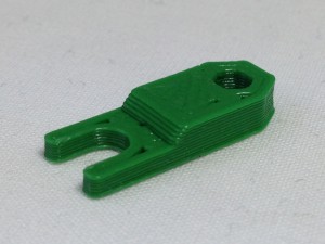
| Now take the retaining tongue out of the drive. |
 |
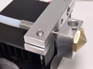
| Push the free end of the Bowden tube, with the slotted brass connector, into the hole in the top of the extruder drive. The slot in the brass connector should be visible in the slot in the printed part; ensure the brass connector is pushed all the way in. |
 |
| The retaining tongue fits in the printed slot as shown, with the flat side of the tongue going upwards. Push the retaining tongue in, until it is firmly engaged with the slotted brass connector. The hole in the end will help you to remove it, if you need to. |
 |


