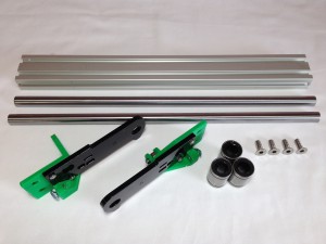
Y axis sub-assemblies
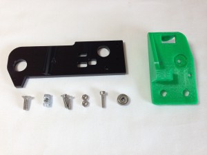
Y-idler-end
TIP: There’s a list of the Ormerod printed parts on
THIS PAGE. Click on the ‘Location’, to see a preview of the printed part, if you’re not sure what it is.
| # |
Component |
Qty |
Type |
|
y-idler-bracket |
1 |
Printed |
|
y-axis-end-plate ‘A’ |
1 |
Lasercut |
|
M4x12mm countersunk socket head screw |
1 |
Fastener |
|
M4 T-nut |
1 |
Fastener |
|
M3x12mm countersunk socket head screw |
2 |
Fastener |
|
M3 Nut |
2 |
Fastener |
|
M3x12mm cap head screw |
1 |
Fastener |
|
623 bearing (10mm diameter) |
1 |
Fastener |
|
 |
TIP: Click on pictures in the instructions to see a larger version. Right-click and select ‘Open link in new Tab’ to see the full size image.
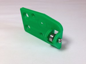
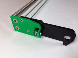
| Fit the 623 idler bearing to the y-idler-end. It may require a fair bit of force to push the bearing into position. It is held in place by a M3x12mm cap head screw. This should self-tap into the printed part, with no need for a nut on the free end. |
 |
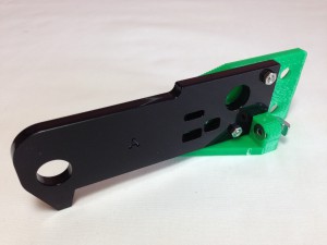
| Using the M3x12mm countersunk socket head screws, assemble the y-axis-end-plate ‘A’ with the y-motor-bracket, with an M3 nut on the back of each screw. |
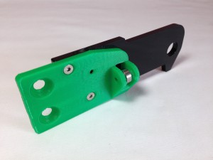 |
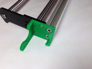
| The M4x12mm countersunk socket-head screw goes through the y-idler-mount as shown, with the T-nut on the other side. Leave the T-nut loose – it connects with the aluminium extrusion. |
 |
Y-motor-end
| # |
Component |
Qty |
Type |
|
y-motor-bracket |
1 |
Printed |
|
y-axis-end-plate ‘B’ |
1 |
Lasercut |
|
M4x12mm countersunk socket head screw |
1 |
Fastener |
|
M4 T-nut |
1 |
Fastener |
|
M3x12mm countersunk socket head screw |
2 |
Fastener |
|
M3 Nut |
2 |
Fastener |
|
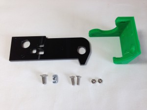 |
| Begin by assembling the Y-motor-end. Use y-axis-end-plate ‘B’ (there is a small ‘B’ engraved on one side of the plate) with the y-motor-bracket. As the y-axis-end-plate is laser-cut acrylic, the 12mm holes will be slightly larger in diameter on one side of the y-axis-end-plate (the side with the letter ‘B’) which will make it easier to insert the 12mm ground steel bar later. |
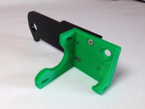 |
| Using the M3x12mm countersunk socket-head screws, connect the two parts together as shown, with an M3 nut on the back of each.. |
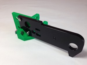 |
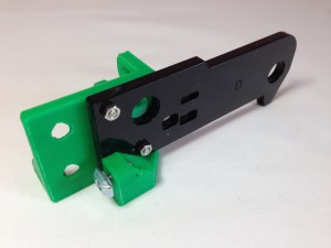
| The M4x12mm countersunk socket-head screw goes through the y-motor-mount as shown, with the T-nut on the other side. Leave the T-nut loose – it connects with the aluminium extrusion. |
 |
Y axis frame
The next step is to assemble the Y axis frame. For this you will need the following:
| # |
Component |
Qty |
Type |
|
y-motor-end |
1 |
Assembled |
|
y-idler-end |
1 |
Assembled |
|
Aluminium extrusion |
1 |
Hardware |
|
Smooth rod 12x350mm |
2 |
Hardware |
|
LM12UU Linear bearing |
3 |
Hardware |
|
M6x16mm countersunk socket head screw |
4 |
Fastener |
|
 |
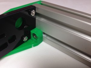
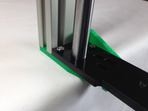
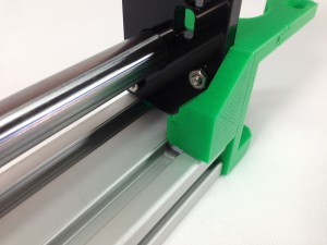
| Screw the y-idler-end onto the aluminium extrusion, using two M6x16mm countersunk socket screws. These screws need to be tight – if they are loose, the Y-ends will move in relation to the aluminium extrusion, and the X axis will not be level to the bed. |
 |
| On the inside of the y-idler-end, check that the M4 T-nut is located in the extrusion slot. |
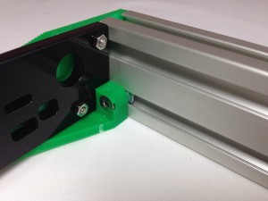 |
| As you tighten the screw, the T-nut should rotate 90 degrees in the extrusion, from horizontal to vertical. It may need a little help! If it can’t rotate, it may have started too close to the printed part; loosen the screw off a couple of turns, then try tightening again. Once it has rotated so that it is vertical, fully tighten the screw. |
 |
| With the y-idler-end supported by the edge of a table, take one of the 12x350mm smooth rods and push it into the hole in the acrylic end piece that is closest to the aluminium extrusion. The 12mm diameter holes are sized to be an interference fit with the rods, and the Acrylic laser cut plates are quite brittle so care must be taken when inserting the rods not to break the end plates. You can use a piece of wood, or soft-faced hammer, to tap gently on the end of the rod, if necessary. |
 |
| NOTE: Some 12x350mm smooth rods may be a little longer, due to variability in manufacture. The y-idler-end printed part can accommodate this, with a pocket. The other places that the rods are used can similarly accommodate these rods (Z axis), or it doesn’t matter (X axis, Y axis front rod) – the longer rod will simply poke out the end a millimetre or so. |
| With the acrylic supported, push the second 12x350mm smooth rod into the hole in the end of the plate. Keep the rod perpendicular to the plate whilst pushing. Try to keep both rods upright, so they do not stress the holes in the Acrylic. |
 |
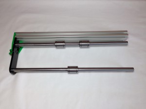
| Slide the LM12UU Linear bearings onto the smooth rod. Put two onto the rod closest to the aluminium extrusion, and one on the front rod. Check they slide smoothly and freely. |
 |
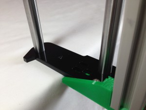
| Push the y-motor-end onto the smooth rods at the other end. This may be easiest with the Y axis vertical. Make sure the acrylic part is supported when pushing the rods in. Try and keep the smooth rods as straight as possible, to avoid damaging the acrylic parts. Push them home, so that the motor mount is flush with the aluminium extrusion. Again, only tap them in with a piece of wood, or soft-face hammer, to avoid damaging the parts. |
 |
| Screw the y-motor-end onto the aluminium extrusion, using two M6x16mm countersunk socket screws. These screws need to be tight – if they are loose, the X axis will not be level to the bed. |
 |
| Ensure the M4 T-nut is located in the extrusion slot, and tighten. |
 |
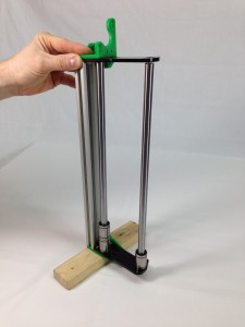
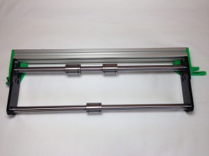
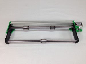
| The completed assembly. Check all screws are tight. |
 |
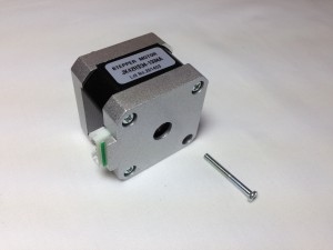
Y axis motor
Now you can fit the Y axis motor. For this step you will need the following:
| # |
Component |
Qty |
Type |
|
y-axis-frame |
1 |
Assembled |
|
NEMA17 stepper motor |
1 |
Hardware |
|
M3x8mm countersunk socket screw |
2 |
Fasteners |
|
M3x40mm cap head screw |
1 |
Fasteners |
|
M3 washer |
1 |
Fasteners |
|
 |
| One screw needs to be removed from the back of the motor, as shown. Don’t lose this M3x26mm crosshead screw; we’ll be using it for the y-carriage. |
 |
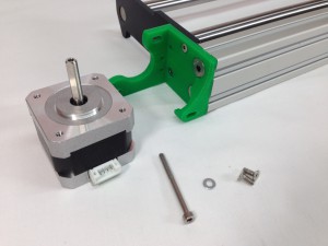
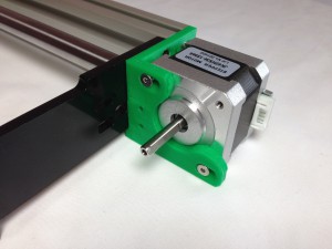
| Fit the motor into the printed y-motor-bracket. Secure the motor in place with 2 x M3x8mm countersunk socket screws in the front face. |
 |
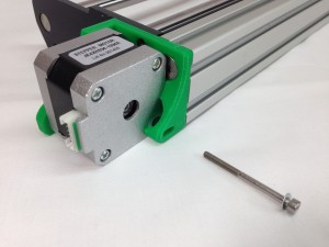
| Put one M3x40mm cap head screw with an M3 washer, in the back of the motor, where you took out the motor screw. |
 |
| The three screws of the motor are mounted in slots, so you can slide the motor a small distance. This allows you to adjust the belt tension, once the belt is fitted. Leave the screws hand tight with the motor at the right-hand end of the slots in the picture. |
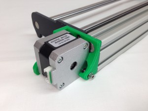 |
| The completed y axis assembly. |
 |


