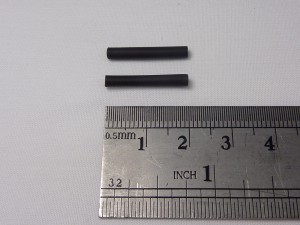
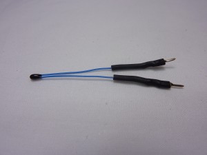
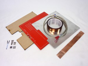
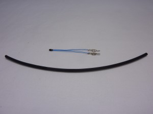
Bed thermistor assembly
The bed thermistor measures the temperature of the heated bed.
|
 |
Heated bed assembly
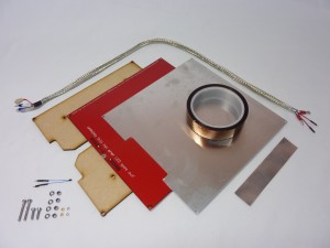
The heated bed helps the extruded plastic stick to the build surface, and improves the print quality.
| Bend the thermistor bead at 90 degrees to the wire. | 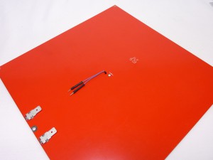 |
| The thermistor bead fits into the central hole in the heated bed PCB. Secure it in place with some Kapton tape, with the legs of the thermistor pointing towards the PCB contacts. | 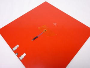 |
| Make sure the thermistor protrudes through the hole in the PCB a little. It will then have good contact with the aluminium heat spreader, and temperature readings will be more accurate. |  |
| It’s a good idea to put a piece of Kapton tape over the bed contacts, so you cannot inadvertently short circuit the bed. | 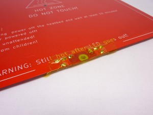 |
| Put heatshrink on the female crimps of the two smaller wires of the wiring loom, if there is none. Covering any exposed metal, but leave the hole in the end of the crimp clear. These wires connect to the thermistor and have to be insulated from each other, and any other part of the heated bed, or you will get incorrect temperature readings, or possibly short circuit the thermistor. | 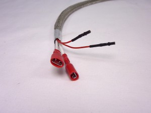 |
| Connect the wiring loom to the thermistor. The thermistor has no polarity, so it doesn’t matter which way around you connect them. The thermistor wires need to sit in the slot of the MDF bed insulator. Hold It in place with a piece of Kapton tape. Put this over the connection between the thermistor and the loom; it’s extra insulation in case there is metal poking through, that could come in contact with the metal tape, which is fitted in the next step. | 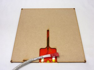 |
| Tape the wires in place with the metal tape, checking the wires sit between the MDF bed insulator. This shields the thermistor wire from ElectroMagnetic Interference (EMI). | 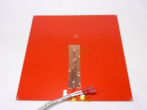 |
| Push the bed wiring loom crimps onto the tabs on the heated bed. Make sure they are pushed fully on. The bed has no polarity, so they can go on either way around. The wires will be closer to the bed if you put the flat side of the crimp towards the bed, as shown. | 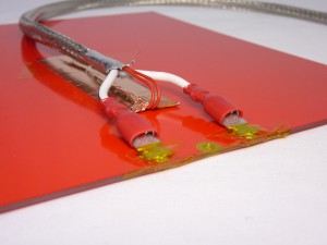 |
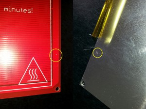
| CAUTION! Wipe the aluminium heat spreader with a paper towel, to remove any metal swarf, and carefully check it for damage, burrs or projections before final assembly. Any scrapes or sharp protrusions from the aluminium heat spreader may scratch the PCB, and short circuit through the aluminium heat spreader, which may result in damage to the electronics. |
 |
| Line up the aluminium heat spreader with the PCB, making sure that it doesn’t touch the contacts. | 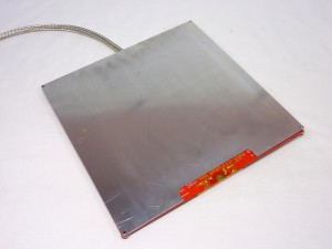 |
| Turn the bed over, and put the MDF bed insulator in place. | 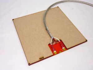 |
| Now assemble the heated bed by putting two M3x12mm cap head screws through the two corners of the bed at the connector end, each side of the PCB contacts. The order should be aluminium heat spreader, PCB, MDF, M3 washer, M3 nyloc nut. | 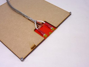 |
| Put two M3x25mm cap head screws through the back corners of the bed. The order should be: aluminium heat spreader, PCB, MDF, M3 washer, M3 nyloc nut. | 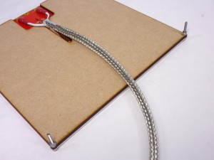 |
| Test the thermistor wiring at the end of the wiring loom; the resistance should be around 10k ohms. It was a warm day when we took this picture, around 28C, so the reading is lower, at 8.48k ohms. Remember that you have a resistance, which will become apparent with a wrong value if you hold both wires in your fingers… | 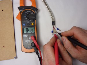 |
| Test the heated bed power wires are making a good connection by testing the resistance. This measures the resistance of the heated bed, and it should be around 1.3 ohms. You may need to wait for a few seconds for the figure to stabilise. Make sure you have a good battery in your multimeter and check that when you short its leads it reads 0 ohms, or your reading may be inaccurate. | 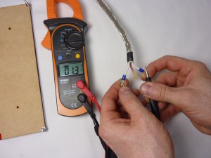 |
| Finally, test there is NO continuity (i.e. infinite resistance) between the aluminium heat spreader and the contacts of the heated bed. If there is continuity, there is a connection between them somewhere, and possibly the heated bed PCB has been damaged. See the earlier warning in red in this section. | 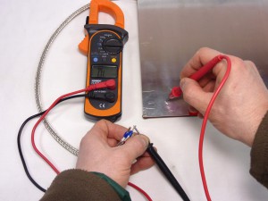 |
| The completed heated bed assembly. | 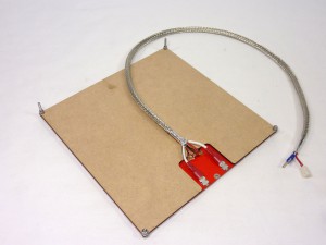 |
|
 |
| The thermistor bead fits into the central hole in the heated bed PCB. Secure it in place with some Kapton tape, with the legs of the thermistor pointing towards the PCB contacts. | 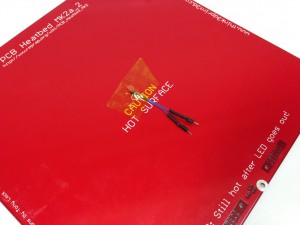 |
| Make sure the thermistor protrudes through the hole in the PCB a little. It will then have good contact with the aluminium heat spreader, and temperature readings will be more accurate. | 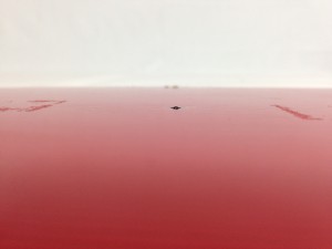 |
| It’s a good idea to put a piece of Kapton tape over the bed contacts, so you cannot inadvertently short circuit the bed. (The rest of the pictures in this sequence do not show this, but fit it now.) | 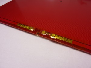 |
| Put heatshrink on the female crimps of the two smaller wires of the wiring loom, if there is none. Covering any exposed metal, but leave the hole in the end of the crimp clear. These wires connect to the thermistor and have to be insulated from each other, and any other part of the heated bed, or you will get incorrect temperature readings, or possibly short circuit the thermistor. | 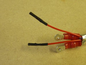 |
| Connect the wiring loom to the thermistor. The thermistor has no polarity, so it doesn’t matter which way around you connect them. The thermistor wires need to sit in the slot of the MDF bed insulator. | 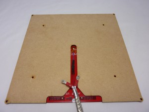 |
| IMPORTANT: Hold the thermistor wires in place with a piece of Kapton tape. Put this over the connection between the thermistor and the loom; it’s extra insulation in case there is metal poking through, that could come in contact with the metal tape, which is fitted in the next step. | PICTURE TO COME |
| Tape the wires in place with the metal tape, checking the wires sit between the MDF bed insulator. This shields the thermistor wire from ElectroMagnetic Interference (EMI). | 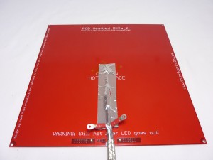 |
| Connect the crimped eyelets to the M2 brass screws. The sequence should be eyelet – spring washer – M2 nut. Make sure the crimped eyelets are flat against the bed; they won’t fit on the brass screws if they are the other way up. | 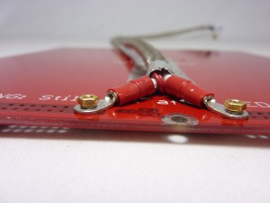 |
| The power terminals should fit into the MDF bed insulator as shown. Get them in the correct place before fully tightening. | 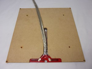 |
| CAUTION! Wipe the aluminium heat spreader with a paper towel, to remove any metal swarf, and carefully check it for damage, burrs or projections before final assembly. Any scrapes or sharp protrusions from the aluminium heat spreader may scratch the PCB, and short circuit through the aluminium heat spreader, which may result in damage to the electronics. |
 |
| Line up the aluminium heat spreader with the PCB, making sure that it doesn’t touch the contacts. | 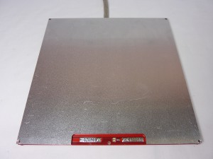 |
| Now assemble the heated bed by putting two M3x12mm cap head screws through the two corners of the bed at the connector end, each side of the PCB contacts. The order should be aluminium heat spreader, PCB, MDF, M3 washer, M3 nyloc nut. | 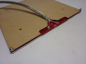 |
| Put two M3x25mm cap head screws through the back corners of the bed. The order should be: aluminium heat spreader, PCB, MDF, M3 washer, M3 nyloc nut. | 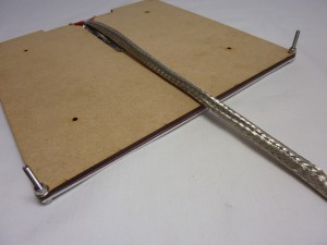 |
| Test the thermistor wiring at the end of the wiring loom; the resistance should be around 10k ohms. It was a warm day when we took this picture, around 28C, so the reading is lower, at 8.48k ohms. Remember that you have a resistance, which will become apparent with a wrong value if you hold both wires in your fingers… |  |
| Test the heated bed power wires are making a good connection by testing the resistance. This measures the resistance of the heated bed, and it should be around 1.3 ohms. You may need to wait for a few seconds for the figure to stabilise. Make sure you have a good battery in your multimeter and check that when you short its leads it reads 0 ohms, or your reading may be inaccurate. |  |
| Finally, test there is NO continuity (i.e. infinite resistance) between the aluminium heat spreader and the contacts of the heated bed. If there is continuity, there is a connection between them somewhere, and possibly the heated bed PCB has been damaged. See the earlier warning in red in this section. You can cover any exposed copper on the heated bed with a small piece of Kapton tape, then re-assemble the bed and test again. | 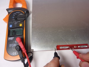 |
| The completed heated bed assembly. | 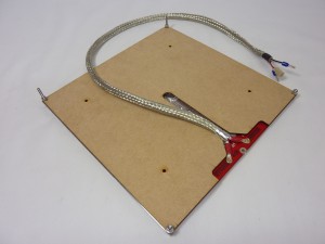 |
Mounting the heated bed
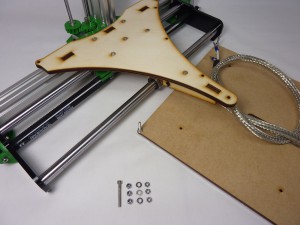
The heated bed can now be mounted on the x-carriage.
|
 |
| Put the M3x25mm cap head screws up through the end of the y-carriage, as shown. Put an M3 washer on, then an M3 nut, and tighten. The M3 nyloc nut goes on part-way. The heated bed will sit on this, and it will provide adjustment for levelling the heated bed manually. | 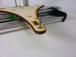 |
| Put the other two M3 nyloc nuts on the M3x25mm cap head screws on the heated bed. These will provide levelling adjustment for the back of the bed. | 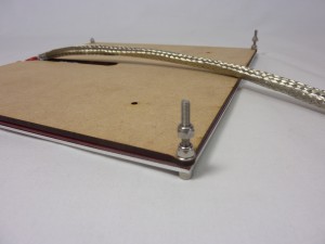 |
| Use two cable ties to loosely attach the heated bed wiring to the edge of the y-carriage. This is important; it stops the hot end cable moving at the connections. The cable will bend along it’s length as the y-carriage moves, not at one point. | 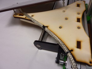 |
| Place the heated bed assembly on the y-carriage. It is mounted on three points, and the nyloc nuts provide manual height adjustment. Put the two M3 washers on top of the y-carriage, so that the two M3 nyloc nuts at the back of the bed rest on them. | 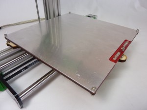 |
| Use two M3 nuts as lock nuts under the y-carriage. You can move the y-carriage to the far end to make it easier to put them on. | 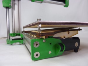 |
| Slide the y-carriage to the other end of the axis to put the other M3 nut on. | 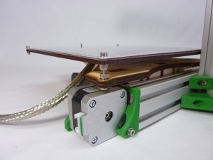 |
| The final M3 nut fits on top of the heated bed PCB, on the M3x25mm screw that points upwards through the end of the y-carriage. It holds the front of the heated bed down. The M3 nut is not shown in this picture, but put it in it’s place! | 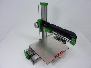 |
Print surface
The glass print surface must be prepared before fitting onto the machine.
|
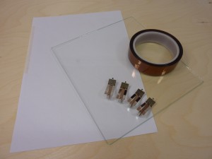 |
| Cut the plain white paper into four 25mm x 25mm squares. Alternatively, you can use white adhesive labels, which makes it easier to stick them on the glass before covering them with Kapton. Stick the paper squares to the four corners of the glass plate, roughly 5mm from the edge. These will act as targets for the proximity sensor, for homing the Z axis, and for bed levelling. The paper targets are on top of the glass, not underneath, so we can use the close accuracy of the proximity sensor. | 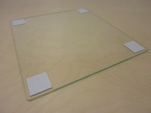 |
| Cover the glass plate and paper targets with one layer of Kapton tape. We stick the Kapton tape to the top edge of the glass, then pull enough out to cover one length. Put a little tension on the tape to keep it straight, then lower it onto the glass. Work down the tape with your finger, flattening it onto the glass, and pushing out any air bubbles. | 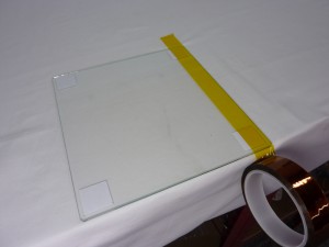 |
| We find it easiest to work on the edge of the table, to drop the Kapton tape roll over the edge. Trim the excess off as we go. Take care to exclude bubbles; working on a white surface helps to spot them. Don’t pull the tape too taught before you lay it down. Gaps between the strips are preferable to overlaps. | 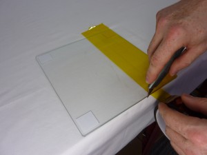 |
| Completely cover the glass, then trim any excess off flush with the edge. Try not to wrap the Kapton tape under the glass. Another way to apply the Kapton tape is to slide it on with soapy water, move it into position, then squeegee out the water. You have to wait for it to dry out before use. | 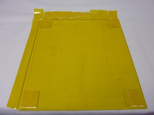 |
| The Kapton is used as the print surface, so the bed should be installed Kapton-side-up. The other side is plain glass, and sits against the aluminium heat spreader. The paper targets should be on top of the glass, and the Kapton on top of the paper targets and glass. | 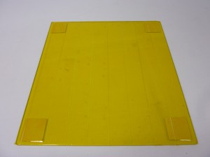 |
| Install the print surface on the heated bed with the clips provided. The glass side should be in contact with the aluminium heat spreader. The clips go around the glass and the heated bed. | 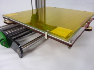 |
| Locate the tab on the end of the clip in the hole in the MDF, which will hold the clip in place. | 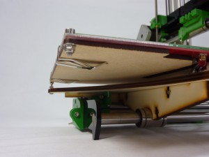 |
| It is important that the print surface is kept free from dirt and oil, including fingerprints; these will stop your prints sticking to the bed. Wipe it clean with a paper towel and acetone (commonly found in nail polish remover, though be careful that does not contain lanolin or any other oil or grease – read the ingredients on the label). isopropyl alcohol, white methylated spirits and white vinegar should also work – all of these are organic solvents, and dissolve oil and grease into the towel before the residue evaporates. Don’t use Windex/Windowlene or polish; they often have a non-stick component! | 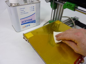 |
| The completed assembly. | 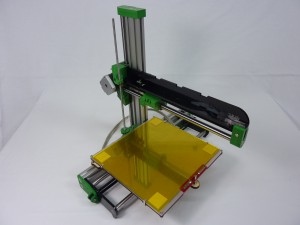 |

