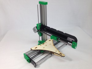
The X axis assembly can now be mounted to the previously assembled ZY assembly.
Z axis leadscrew
The Z axis leadscrew moves the X axis up and down.
| # |
Component |
Qty |
Type |
|
z-gear-driven |
1 |
Printed |
|
M5 threaded z-rod |
1 |
Hardware |
|
BZP M5 nut |
3 |
Fastener |
|
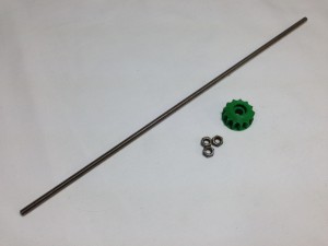 |
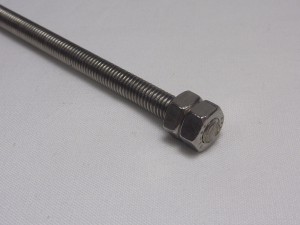
| Make sure the M5 threaded z-rod is clean, with no swarf or other debris in its threads. Screw two M5 nuts onto one end of the M5 threaded z-rod. Tighten one nut against the other, so that they are locked in place, right at the end of the rod. |
 |
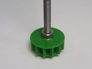
| Push the z-gear-driven onto the locked M5 nuts. The bottom nut of the two should fit into the nut trap in the gear. |
 |
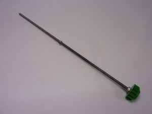
| Screw the last M5 nut onto the z-rod. It should look like this, when assembled. You can lightly oil the threaded rod; see the Maintenance section later in the instructions for guidance. |
 |
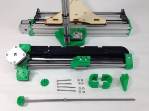
X axis assembly
Now, the x-axis-assembly can be mounted on the z axis. For this, the following parts are required:
| # |
Component |
Qty |
Type |
|
x-axis-assembly |
1 |
Assembled |
|
y carriage and z axis |
1 |
Assembled |
|
z-axis-leadscrew |
1 |
Assembled |
|
z-bearing-clamp |
2 |
Printed |
|
z-nut-trap |
1 |
Printed |
|
z-gear |
1 |
Printed |
|
M3x50mm cap head screw |
2 |
Fastener |
|
M3x40mm cap head screw |
2 |
Fastener |
|
M3 Nut |
4 |
Fastener |
|
M3 washer |
4 |
Fastener |
|
 |
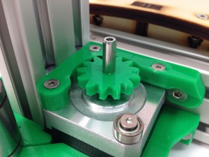
| Press the z-gear onto the z-motor shaft, conical side down. The z-gear has a flat in the hole, that should align with the flat on the motor shaft, which stops the gear rotating on the shaft. The gear should be a tight fit, so make sure you line it up before pushing the gear on the motor shaft. |
 |
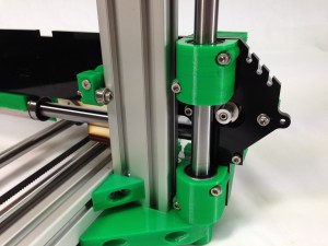
| Slide a z-bearing-clamp onto each z axis linear bearing. Place the two M3x50mm cap head screws in the top mount, and the two M3x40mm cap head screws in the bottom mount, with a washer under each head. |
 |
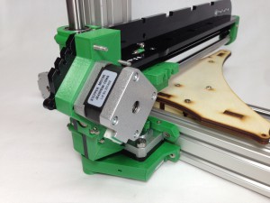
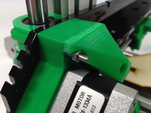
| Take the x-axis-assembly. Hook the z-runner-mount bearing around the z axis aluminium extrusion. |
 |
| Offer up the x-axis-assembly and push the four z-bearing-mount screws through the X axis. The X axis can now sit at the bottom of the Z axis. |
 |
| Use two M3 nuts to secure the bottom z-bearing-mount. Don’t do them up too tight yet. |
 |
| Use a screw to pull an M3 nut into the recessed nut trap, in the z-nut-trap printed part. |
 |
| You may need to push the M3 nut into the nut trap with a screwdriver, but the screw will help to align it correctly. Remove the screw once it is held in place. |
 |
| Push the z-nut-trap onto the end of the 50mm cap head screws, add the remaining M3 nut, and do up the screws, but not tight. |
 |
| Now tighten the bearing mount screws. The holes in the bearing clamps are clearance for the M3 screws, so keep moving the axis up and down between turns of each screw. This will let the bearings settle in the right place, and ensure that the axis runs smoothly. |
 |
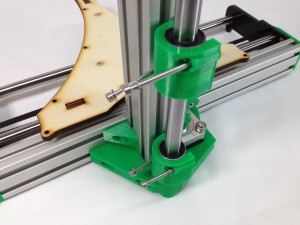
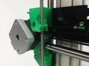
| Lift the X axis to the top of the Z axis, and carefully feed the z-axis-leadscrew assembly up through the z-nut-trap. |
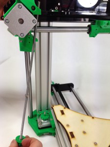 |
| The z-axis-leadscrew sits on the 623 bearing on the corner of the Z axis motor, engaging with the z-gear on the motor. |
 |
| The x-axis-assembly can now be supported by the loose M5 nut on the z-axis-leadscrew. Gently lower the X axis onto it, being careful to orientate the M5 nut correctly – see picture. |
 |
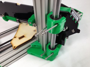
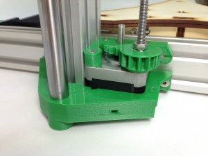
| The completed assembly. Put a little light oil on the Z-axis M5 screw using a cloth. An thin even spread without drips is best. |
 |
Checking for play in the x axis
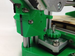
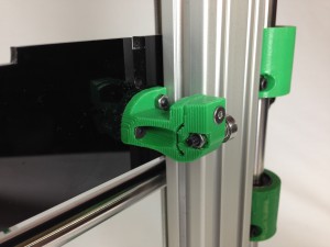
Adjusting the z-runner-mount.
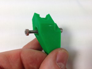
| Rotation of the x-axis around the z-axis is prevented by the z-runner-mount. It is important that the z-axis aluminium extrusion is held securely by the bearings in the z-runner-mount. The outer bearing on the z-runner-mount is mounted on a hinged clamp, which allows the tension to be adjusted. However, don’t over-tighten this, or movement of the Z axis may be compromised. |
 |


