X axis sub-assemblies
The first step is to assemble a couple of sub assemblies.
x-axis-motor
The x-axis-motor moves the x-axis belt.
| # |
Component |
Qty |
Type |
|
NEMA17 motor |
1 |
Hardware |
|
MXL pulley |
1 |
Hardware |
|
M3 grub screw |
1 |
Hardware |
|
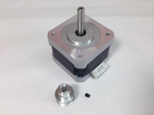 |
| Screw the grub screw partially into the pulley. The motor shaft has a flat on it; align the grub screw with this. For the X axis, the pulley goes on the shaft with the pulley teeth closest to the motor body. |
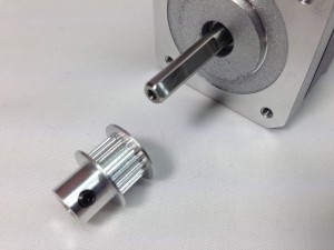 |
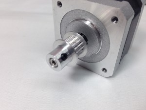
| Put the pulley on the motor shaft, and tighten the grub screw using a 1.5mm Allen key. The pulley needs to sit right on the very end of the motor shaft, as shown in the picture. |
 |
x-idler
The x-idler is at the other end of the x-axis from the x-motor, and carries the bearing for the x-axis belt.
| # |
Component |
Qty |
Type |
|
x-idler-bracket |
1 |
Printed |
|
623 bearing (10mm diameter) |
1 |
Hardware |
|
M3x25mm countersunk socket screw |
1 |
Fastener |
|
M3 Nut |
1 |
Fastener |
|
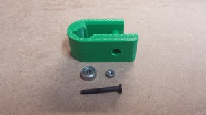 |
| Push the countersunk screw through the x-idler-bracket. The hole may be a little tight where it breaks through to the gap in the middle of the x-idler-bracket. Place the bearing inside the x-idler-bracket and fit the M3 nut to the protruding screw. |
 |
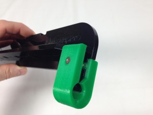
| Pull the M3 nut into the ‘nut trap’, but leave the assembly loose at this stage. A ‘nut trap’ is a hole in a printed part that is designed to hold a nut ‘captive’. |
 |
x-carriage
The x-carriage is connected to the x-axis belt, and travels along the X axis, carrying the hot end.
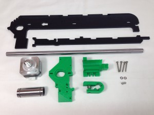
X axis assembly
Now you can start to assemble the X axis.
| # |
Component |
Qty |
Type |
|
x-carriage |
1 |
Assembled |
|
x-idler |
1 |
Assembled |
|
x-axis motor |
1 |
Assembled |
|
x-motor-bracket |
1 |
Printed |
|
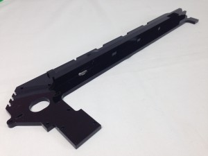
x-axis-plate |
1 |
Laser cut |
|
x-rib |
1 |
Laser cut |
|
Smooth rod 12x350mm |
1 |
Hardware |
|
LM12LUU linear bearing |
1 |
Hardware |
|
M3x25mm cap head screw |
4 |
Fasteners |
|
M3 Nut |
2 |
Fasteners |
|
M3 washer |
2 |
Fasteners |
|
 |
| Push the x-rib into place in the slots in the x-axis-plate, which should slot together easily. DO NOT FORCE! Acrylic is quite brittle, and you may break the x-rib. Use a file to smooth any rough edges, and ease the tabs of the x-rib, so it goes into the x-axis-plate easily. The x-axis-plate should be perfectly flat; if it is bowed or twisted, the x-carriage will not run straight and true. |
 |
| Make sure the screw through the x-idler sub-assembly is loose. Push the x-idler onto the end of the x-axis-plat and x-rib as shown, making sure it goes on straight. |
 |
| Slide the smooth rod into the x-motor-bracket. |
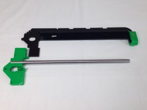 |
| Then slide the linear bearing onto the bar, then the x-carriage. You need to fit the x-carriage now, as it won’t fit on once the smooth rod is connected to the x-idler (next step). Don’t push the x-carriage onto the bearing yet, as it needs to be off the bearing to attach the x-axis-drive-belt. |
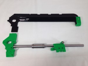 |
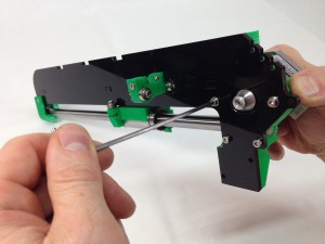
| Push the smooth rod into the x-idler. Be careful not to bend or twist the acrylic parts. |
 |
| Push the x-motor-bracket until it buts up to the x-rib. Ensure you have the parts lined up before applying too much pressure as the acrylic parts are not very forgiving. You may find this easier if you do it vertically, with the x motor bracket supported by the edge of a bench just under the smooth rod, but don’t let the assembly drop to the floor… |
 |
| The x-carriage runner bearing should be behind the x-axis plate for the old version of the x-carriage (528.4 and earlier). If you’re using the newer version of the x-carriage (528.5 onwards), the bearing runs on the underside of the x-axis-plate. See last picture in the preceding section. |
 |
| Insert two of the M3x25 screws in the top and bottom holes in the x-motor-bracket, to act as guide screws, and to hold the x-motor-bracket in place. Check that the x-motor-bracket fits in place; it may need trimming for a good fit around the x-rib. Make sure all the M3 holes in the printed part line up with the laser cut part – trim as necessary. Put an M3 nut in each nut trap, as shown. |
 |
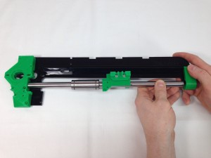
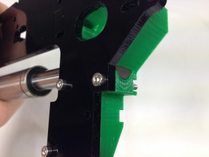
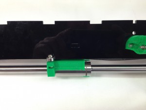
| The smooth rod should butt up to the end of the x-motor-bracket, as shown. Insert two M3x25mm cap head screws to engage with the M3 nuts in the nut traps. Tighten the screws. |
 |
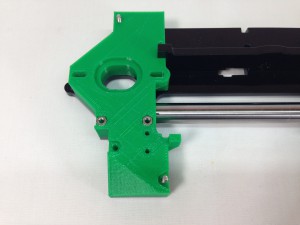
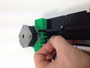
| Remove the two M3x25mm screws that you put in as guide screws. Insert them, with washers on, to mount the motor. Orientate the motor as shown, with the wiring connector pointing out and down from the axis. Do not fully tighten the screws; the motor is mounted in slots to allow for tensioning the x-axis-drive-belt. Slide the motor to the end of the slots nearest the x idler bracket. |
 |
| Tighten the countersunk screw in the x-idler-bracket. |
 |
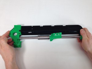
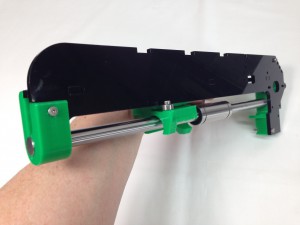
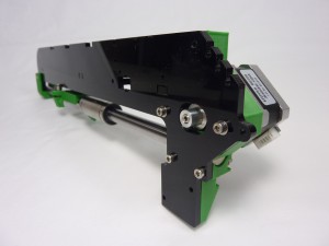
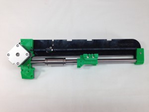
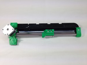
| The completed assembly. |
 |
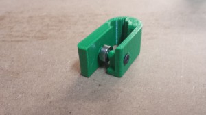
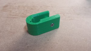
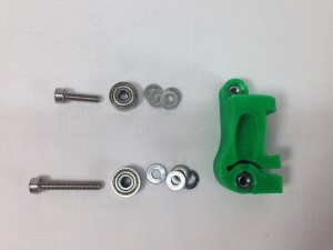
z-runner-mount
The z-runner-mount sub-assembly stops the x-axis rotating around the z-axis.
| # |
Component |
Qty |
Type |
|
z-runner-mount |
1 |
Printed |
|
623 bearing (10mm diameter) |
2 |
Hardware |
|
M3x20mm cap head screw |
1 |
Fastener |
|
M3x12mm cap head screw |
2 |
Fastener |
|
M3x20mm countersunk socket screw |
1 |
Fastener |
|
M3x16mm countersunk socket screw |
1 |
Fastener |
|
M3 Nut |
5 |
Fastener |
|
M3 washer |
9 |
Fastener |
|
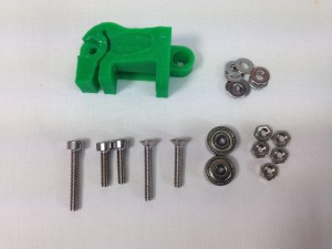 |
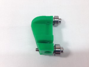
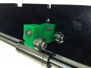
| Put an M3 nut in each nut trap. Make sure they are at the bottom of the nut traps. If they don’t drop straight in, pull them into the nut traps with an M3 screw. Using one M3x20mm cap head screw and one M3x12mm cap head screw, attach the bearings. Put one bearing on each screw, then 4 x M3 washers between each bearing and the z-runner-mount. |
 |
| Assemble as shown in the picture. |
 |
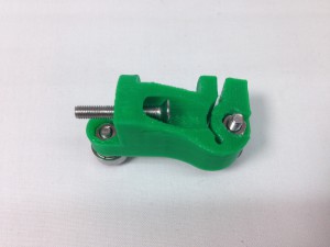
| Put the M3x20mm countersunk screw through the recessed hole in the z-runner-mount. |
 |
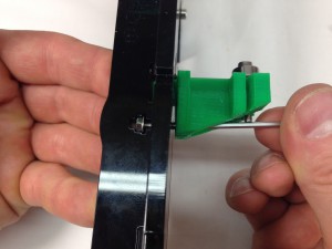
| Put your finger under the captive hole in the x-rib, and drop an M3 washer and M3 nut into it. Mount the z-runner-mount assembly to the x-axis-plate, putting the M3x20mm countersunk screw through the x-axis-plate and into the x-rib, where it is secured by the captive M3 nut and washer. |
 |
| Use the M3x12mm cap head screw, which goes through the x-axis-plate and into the top hole of the z-runner-mount, and is secured with an M3 nut. Check both bearings are free to rotate; add or remove a washer if the bearing in the x-axis-plate is touching the acrylic. |
 |
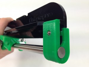
| Use an M3x16mm countersunk socket screw and M3 nut to secure it. DO NOT OVER-TIGHTEN! The z-runner-mount should only need to lightly hold the z axis aluminium extrusion, or the axis will be difficult to move. |
 |
X axis drive belt
To finish the X axis, attach the drive belt.
| # |
Component |
Qty |
Type |
|
x-axis assembly |
1 |
Assembled |
|
MXL belt |
710mm |
Hardware |
|
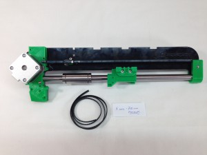 |
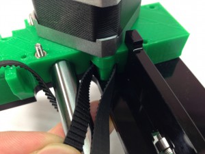
| The X axis drive belt can now be fitted. The 1/4″ MXL belt should be accurately cut to 710mm in length. Insert the belt through the slot in the x-motor-bracket, around the drive pulley and back out through the second slot. |
 |
| This is quite fiddly; moving the motor back and forth will help feed the belt through, as will rotating the motor pulley. You can also push the belt around the back of the pulley, with a small Allen key or screwdriver. |
 |
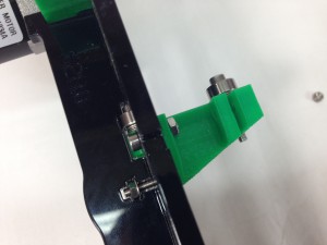
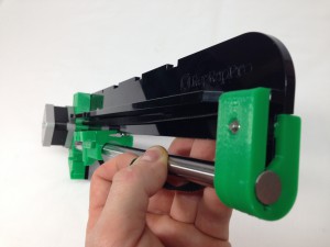
| Twist the top section of belt 180 degrees, and pass it over and around the idler bearing. The smooth side of the belt will be in contact with the bearing. |
 |
| Slide the end of the lower section of belt, from the motor end, into the x-carriage. The end of the belt should be flush with the end of the x-carriage if your belt has been cut to 710mm. Mesh the teeth of the two ends of the belt, and push it into the slot in the x-carriage. |
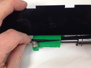 |
| Make sure the belt is pushed fully back in the slot, and that there is as much engagement of the teeth as shown. |
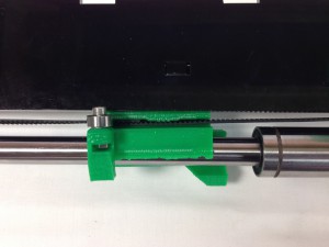 |
| The linear bearing can now be slid into the x-carriage. |
 |
| Tighten the belt by sliding the X axis motor back. Tighten the motor mounting screws. |
 |
| The completed assembly. Check the x-carriage runs smoothly by moving the x-carriage up and down the smooth rod. If it sticks, the bearing may need lubricating. It’s actually the rubber seals on the bearing ends that need lubrication; use a drop of light oil (like 3-in-1 oil or similar) on each side of the bearing and run it up and down. A remaining film of oil on the rod is good. But make sure there are no drips. Also check the belt doesn’t rub at either end; this is usually signified by a little black ‘dust’, which is where the edge of the belt is rubbing. Check the alignment of the motor pulley. If you do the x-idler up very tight, you may need to put an M3 washer on one side of the bearing, to give the belt a little more space. |
 |


