Wiring the Duet
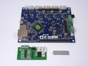
The Duet electronics board controls all the functions of the printer. We use an external 5V regulator board to provide good, clean 5V power.
| # |
Component |
Qty |
Type |
| 394 |
Duet PCB |
1 |
Electronics |
| 597 |
5V regulator PCB |
1 |
Electronics |
| 677 |
DC power link wire |
1 |
Electronics |
|
 |
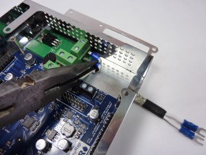
| Cut open the length of 2-core and earth copper cable and extract the blue and brown cores. |
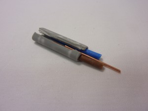 |
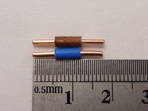
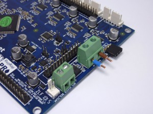
| Strip both ends of each core as shown. These dc-power-links should be about 18mm long, with 6mm of exposed wire each end, and 6mm of insulation. You can slip the brown and blue insulation off the copper wires, cut it to length, and slip it back on. |
 |
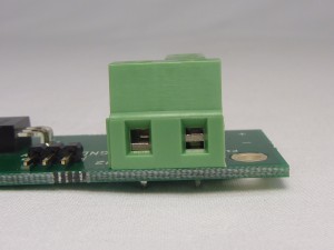
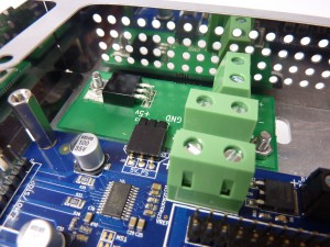
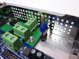
| Make sure that the screw gates of all the screw terminals are OPEN. The gate on the left is open, the one on the right is only partially open. They are usually supplied closed, so unscrew them first, before inserting any wire. The screw terminal is tightened by turning the screw clockwise. If the wires are not tight in the terminals, they will not make a good connection, and possibly cause heat to be generated. |
 |
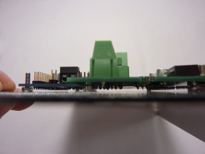
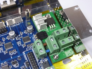
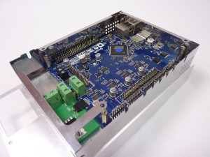
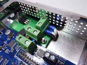
| Insert the dc-power-links into the Duet’s POWER IN screw terminals, and tighten the screw terminals. Make sure the blue and brown wire insulation IS NOT TRAPPED by the screw terminals, or you will have a poor connection. These wires carry a lot of current (for the heated bed), so poor connections can get hot. Cut the insulation shorter, or leave it off, if you need to. |
 |
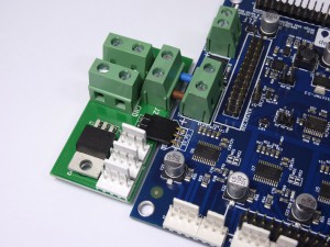
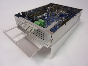
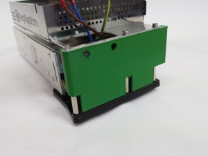
| Push on the 5v regulator PCB and secure to the Duet by tightening the screws of the 5v regulator PCB’s power output terminal. Again, make sure the blue and brown wire insulation IS NOT TRAPPED by the screw terminals, or you will have a poor connection. The three pins on the 5V regulator board should engage in the housing on the Duet. |
 |
Mount the Duet in the enclosure
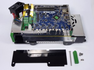
Assemble the electronics enclosure using the following parts:
| # |
Component |
Qty |
Type |
|
Duet board assembly |
1 |
Assembled |
| 578 |
enclosure-perimeter |
1 |
Sheet metal |
| 576 |
enclosure-base |
1 |
Sheet metal |
| 257 |
M3x12mm cap head screw |
6 |
Fastener |
| 258 |
M3 nut |
8 |
Fastener |
| 212 |
M3 washer |
2 |
Fastener |
| 581 |
Hexagonal stand-offs (VBFS-M3-5-16) |
4 |
Fastener |
|
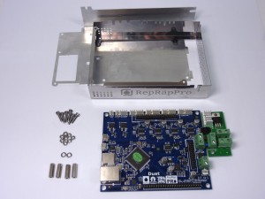 |
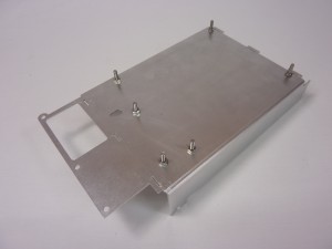
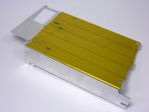
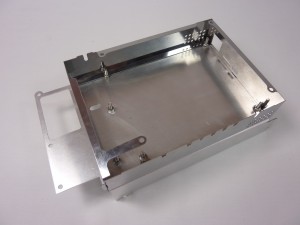
| Start by taking the enclosure-base. All the aluminium parts may have oil on them; wipe them over with a paper towel to remove the oil, and any swarf that may be left over from the cutting process. Take 2 x M3x12mm cap head screws, 2 x M3 washers and 2 x M3 nuts, and mount them LOOSELY, as shown. These two screws hold the 5V regulator PCB. |
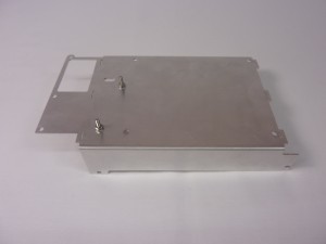 |
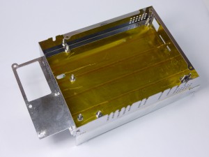
| We’re going to trial mount the Duet PCB, to check that there are no short circuits under boards underneath. Mount the other four M3x12mm cap head screws with an M3 nut each, again LOOSELY, as shown. |
 |
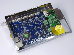
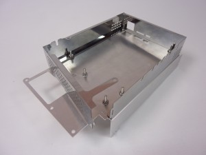
| Place the Duet board on the screws. The nuts act as spacers between the Duet board and the enclosure base. |
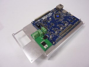 |
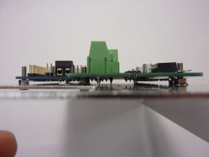
| IMPORTANT: Look between the Duet board and the enclosure base. You do not want any of the soldered pins on the back of the board to touch the metal of the enclosure base. If they are touching and power is applied to the board, it will short circuit, and potentially damage the board. |
 |
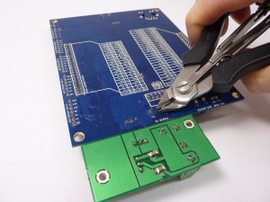
| Trim any long pins with a pair of side cutters. |
 |
| Check again that there is nothing in danger of contacting the enclosure base. Once you are happy nothing is touching, remove the Duet assembly, and remove the four cap head screws with just a nut holding them (no washer). |
 |
| If you wish, you can also put strips of Kapton tape (which is electrically insulating) on the enclosure base, under the Duet. |
 |
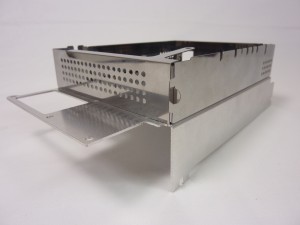
| Take the Duet enclosure perimeter. CARE SHOULD BE TAKEN WITH ITS SHARP EDGES. There are three slots in the enclosure base at each end, which correspond to the tabs in the enclosure perimeter. Make sure they are aligned, then slot the two parts together as shown; a fair amount of pushing force can be required to push the tabs into the slots. Secure the Duet perimeter with the four M3x12mm cap head screws, each with an M3 nut. Assemble LOOSELY; the screws need to be able to move a little, to make it easier to fit the Duet board. |
 |
| Place the Duet assembly in the enclosure. Line up the screws, so it goes on the mounting holes. Bend over the tab that connects the two ends of the perimeter. |
 |
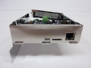
| The USB connector is the longest part. Check it comes through the hole at the end, and that the SD card socket and ethernet socket line up. Once the Duet is in place, tighten the six mounting screws; if you push down on the board, the M3 nuts should bite enough to tighten. |
 |
| Fit the four hexagonal stand-offs on the ends of the mounting screws. This can be quite fiddly, particularly the one by the ethernet socket. To help, screw an M3x8mm countersunk screw into one end of the stand-off, and position the stand-off on the mounting screw with long nosed pliers. Tighten by using an Allen key in the countersunk screw, through the hole in the metal perimeter. Remove the countersunk screw from the stand-off by holding the stand-off with long nosed pliers. Repeat the process until you have tightened all of them. |
 |
| The last two M3 nuts secure the 5V regulator PCB. The one that goes through the component (the 5V regulator) is particularly important; it is used to heatsink this to the enclosure back. Make sure it is securely fixed. |
 |
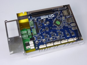
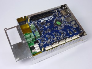
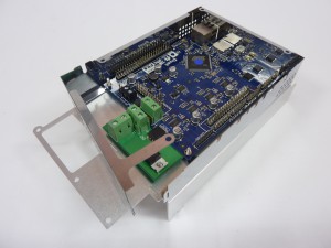
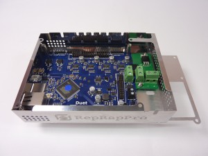
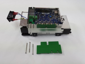
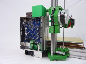
| Check all the M3x12mm cap head screws are tight underneath, and the Duet board is securely held, and the stand-offs are screwed down fully too. The completed assembly is shown here. |
 |
| Take the Duet enclosure perimeter, and fold it until the semi-circular external tag passes through the small slot. CARE SHOULD BE TAKEN WITH ITS SHARP EDGES. Do not bend the tab over yet! There are three slots in the enclosure base at each end, which correspond to the tabs in the enclosure perimeter. Make sure they are aligned, then slot the two parts together as shown; a fair amount of pushing force is required to push the tabs into the slots. |
 |
| Secure the Duet perimeter with the four M3x12mm cap head screws, each with an M3 nut. Assemble LOOSELY; the screws need to be able to move a little, to make it easier to fit the Duet board. |
 |
| Unhook the part of the Duet perimeter with the external tab, and release the three tabs where it goes into the enclosure base. This should give you the space to put the Duet board in. |
 |
| Place the Duet assembly in the enclosure. Line up the screws, so it goes on the mounting holes. |
 |
| The USB connector is the longest part. Check it comes through the hole at the end, and that the SD card socket and ethernet socket line up. |
|
| Once the Duet is in place, refit the enclosure perimeter in the tab slots. Bend over the external tab to secure it. Tighten the six mounting screws; if you push down on the board, the M3 nuts should bite enough to tighten. |
 |
| Fit the four hexagonal stand-offs on the ends of the mounting screws. This can be quite fiddly, particularly the one by the ethernet socket. To help, screw an M3x8mm countersunk screw into one end of the stand-off, and position the stand-off on the mounting screw with long nosed pliers. Tighten by using an Allen key in the countersunk screw, through the hole in the metal perimeter. Remove the countersunk screw from the stand-off by holding the stand-off with long nosed pliers. Repeat the process until you have tightened all of them. |
 |
| The last two M3 nuts secure the 5V regulator PCB. The one that goes through the component (the 5V regulator) is particularly important; it is used to heatsink this to the enclosure back. Make sure it is securely fixed. |
 |
| Check all the M3x12mm cap head screws are tight underneath, and the Duet board is securely held, and the stand-offs are screwed down fully too. The completed assembly is shown here. |
 |
IMPORTANT!
With a multimeter, check the resistance between the screws of the Duet’s POWER IN terminal (between +12V and ground). Except for the charging of capacitors (which will take a few seconds), this should be open circuit. If there is a short circuit (no resistance), double-check no pins of the Duet or 5V regulator board are touching the metal enclosure. Much easier to check now than later!
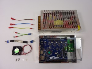
Power supply wiring
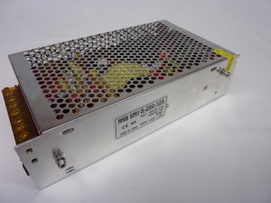
TIP: Some sections of the instructions are arranged in tabs, with alternate parts and instructions, depending on the version of your kit. Below, the tabs are marked ‘528.2 ONWARDS’ and ‘528.0, 528.1’. These refer to the version number of the Ormerod kit. Your Ormerod kit version number is marked on the sticker on the power supply (on 528.2 and later kits ), or on the x-rib (for earlier kits). Use the LATEST version number – some kits have the 528.2 PSU, but the 528.1 x-rib. Use the set of instructions that relate to your printer.
| # |
Component |
Qty |
Type |
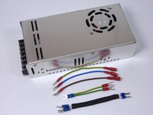
| 831 |
12V Power supply |
1 |
Hardware |
|
Duet assembly |
1 |
Assembled |
| 592 |
AC power cable – 90mm |
3 |
Wiring |
| 668 |
Earth loop wire |
1 |
Wiring |
| 591 |
DC power cable |
1 |
Wiring |
|
 |
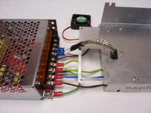
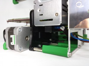
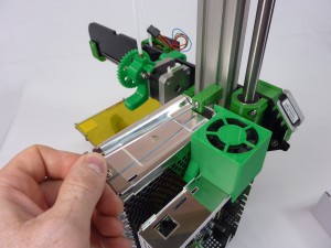
| Pass the ends of the DC power cable up through the slot in the enclosure-base to come out near the power input terminal of the 5v regulator PCB. The wire with the black stripe is used for the V- (ground) terminal. The heat shrink on the cable can act as protection for the wires where they pass through the metal enclosure. |
 |
| Check the screw gates are open, then insert the DC power cable ends into the screw terminal. A pair of long-nosed pliers helps. Ensure that the positive (no stripe) and ground (black stripe) wires are the correct way round. |
 |
| Tighten the screw terminals on the DC cable ends. |
 |
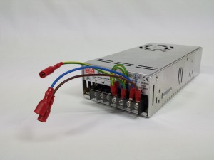
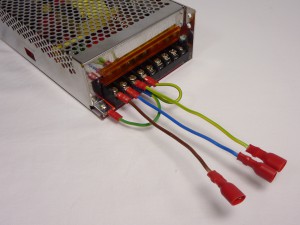
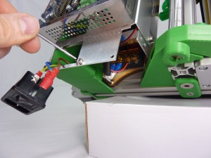
| All of the wires connect to the PSU through insulated spade terminals. Open the small clear connector cover, to access the screws. The brown wire goes to Live, the blue to Neutral, and the green and yellow stripe to Ground/Earth. The Y-shaped earth loop goes from Ground/Earth to the next connector along (COM or Negative/V-). Make sure the screw terminals are tight, and the wires are secure. |
 |
| # |
Component |
Qty |
Type |
| 218 |
12V Power supply |
1 |
Hardware |
|
Duet assembly |
1 |
Assembled |
| 592 |
AC power cable – 90mm |
3 |
Wiring |
| 668 |
Earth loop wire |
1 |
Wiring |
| 591 |
DC power cable |
1 |
Wiring |
| 953 |
12V fan (if supplied) |
1 |
Electronics |
| 111 |
M3x8mm cap head screw |
2 |
Fastener |
| 212 |
M3 washer |
2 |
Fastener |
|
 |
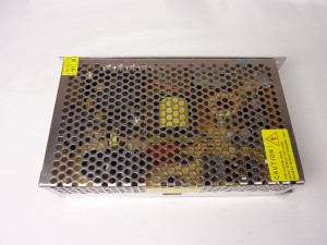
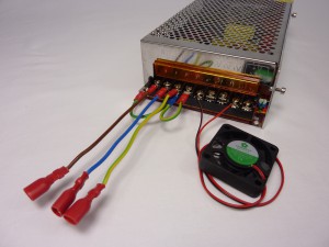
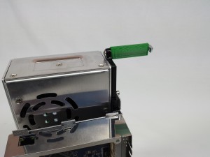
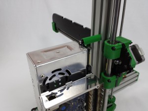
| Since mid-October 2014, we now ship PSUs with an integrated fan, which is just visible in the picture, inside the PSU in the upper left hand side, secured by two screws to the top of the case. If you have one of these, you do not need to fit the extra PSU cooling fan. |
 |
| Pass the ends of the DC power cable up through the slot in the enclosure-base to come out near the power input terminal of the 5v regulator PCB. The wire with the black stripe is used for the V- (ground) terminal. The heat shrink on the cable can act as protection for the wires where they pass through the metal enclosure. |
|
| Check the screw gates are open, then insert the DC power cable ends into the screw terminal. A pair of long-nosed pliers helps. Ensure that the positive (no stripe) and ground (black stripe) wires are the correct way round. |
|
| Tighten the screw terminals on the DC cable ends. |
|
| Take the power supply, and screw the M3x8mm cap head screws into the side of the power supply unit, with an M3 washer on each screw, leaving them loose as shown. |
 |
| All of the wires connect to the PSU through insulated spade terminals. Lift the small orange connector cover. The brown wire goes to Live, the blue to Neutral, and the green and yellow stripe to Ground/Earth. The Y-shaped earth loop goes from Ground/Earth to the next connector along (COM or Negative/V-) and to the corner of the case, under the tab (closest to the camera in the picture). Make sure the screw terminals are tight, and the wires are secure.NOTE: Ormerod 2 kits shipped before November 2014 will have a single earth loop, not a Y-shaped one. Either add a second earth wire, or contact RepRapPro support for the correct wire. |
 |
| (Ignore this step if your PSU has an integrated fan.) Cut the fan wire to about 30cm long. Strip about 8mm of insulation from the end, and tin them with solder if you wish. There are three V- terminals, next to the AC power input terminals, then three V+ terminals. There is diagram of the inputs and outputs on the back of the PSU, but it may not line up with the terminals, so be careful! Connect the black wire to V- on the PSU, and the red wire to V+. |
 |
| Connect the DC power cable from the Duet to the 12V PSU. The wire with the black stripe should be negative; connect it to V-, and connect the other wire to V+. |
 |
Power supply covers
Mounting the Duet on the power supply
Fitting the IEC socket
PSU lower cover
| # |
Component |
Qty |
Type |
|
PSU and Duet assembly |
1 |
Assembled |
| 820 |
psu-cover |
1 |
Printed |
| 465 |
M3x50mm cap head screw |
3 |
Fastener |
|
 |
| Fit the psu-cover using the M3x50mm cap head screws. |
 |
Final mounting
| # |
Component |
Qty |
Type |
|
PSU and Duet assembly |
1 |
Assembled |
| 821 |
psu-brace |
1 |
Printed |
| 822 |
outer-psu-plate (3mm acrylic) |
1 |
Laser cut |
| 829 |
M4x50mm button head screw |
2 |
Fastener |
| 651 |
M4x10mm button head screw |
2 |
Fastener |
| 497 |
M4 T-nut |
1 |
Fastener |
|
 |
| Fit the psu-brace using the M4x50mm button head screw and T-nut. |
 |
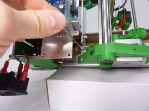
| Before fitting the PSU, remove the M3x40mm cap head screw that holds the Y motor. Engage the two T-nuts in the Y axis aluminium extrusion, through the IEC socket hole, but do not fully tighten, so you can adjust the position of the PSU assembly. Use the M3x50mm cap head screw with an M3 washer, through the two acrylic laser cut parts, and screw into the Y motor. |
 |
| Slide the PSU assembly to engage the T-nut of the psu-brace into the Z axis aluminium extrusion. Adjust the position of the PSU assembly, then tighten the two lower T-nuts and the psu-brace mounts as necessary. |
 |
| Screw the outer-psu-plate to the PSU using the M4x10mm button head screws. |
 |
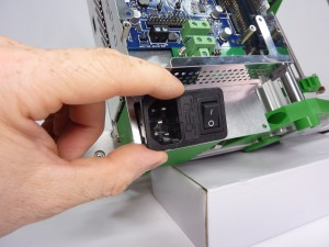
| Finally, push the IEC socket into the aperture in the enclosure base, with the power cord socket on the outside edge. Push the wires back into the housing and push the IEC socket into the aperture until it clicks. |
 |
| Mount the power supply assembly to the y-axis aluminium extrusion. The T-nut on the right-hand-side is the most fiddly; secure this one first, so that the T-nut has turned and engaged, but don’t fully tighten it, so the position of the PSU assembly can be adjusted. |
 |
| Engage the second T-nut, through the IEC socket hole. |
 |
| Put the M4x35mm button head screw though the psu-brace printed part, and put an M4 T-nut on the end. The psu-brace can then be slid onto the top of the power supply unit, and secured into the Z axis aluminium extrusion. Adjust then tighten the two lower T-nuts mounts as necessary. |
 |
| Finally, push the IEC socket into the aperture in the enclosure base, with the power cord socket on the outside edge. Push the wires back into the housing and push the IEC socket into the aperture until it clicks. |
|
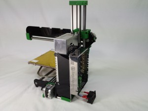
| The completed, and mounted, PSU and Duet assembly. |
 |


