Y carriage assembly
The Y carriage can now be assembled and fitted. You will need the following parts:
| # |
Component |
Qty |
Type |
|
bed-support (6mm ply) |
1 |
Laser cut |
|
y-axis-rib (6mm ply) |
1 |
Laser cut |
|
y-axis-cross-rib (6mm ply) |
1 |
Laser cut |
|
M3x16mm countersunk socket screw |
4 |
Fastener |
|
M3 nut |
4 |
Fastener |
|
M3 washer |
4 |
Fastener |
|
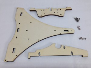 |
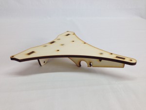
| The y-axis-rib and y-axis-cross rib slot into the bed-support. Make sure the holes in the edge of the bed-support are on the left; these are used to attach the bed wiring later. |
 |
| Secure the bed-support to the Y axis ribs using the four M3x16mm countersunk socket screws. An M3 washer and M3 nut go in the captive holes of the Y axis ribs. The easiest way to do this is to hold the bed vertically, and put your finger under the hole. Drop the washer in, then the nut. |
 |
| Then thread the M3x16mm countersunk socket screw through from the top of the bed-support, so it engages with the nut. Repeat for the other three nut traps between the ribs and bed-support. Tighten all of them. |
 |
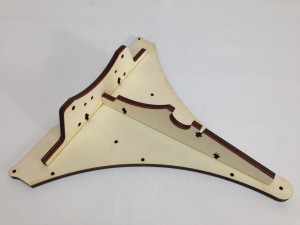
| Make sure the bed-insulator is orientated correctly, as shown in the picture. The holes for the wiring are on the right-hand side when the y-carriage is the correct way up as in this picture. |
 |
Y-carriage mounting
Fit the y-carriage to the assembled y-z-axis assembly. The following parts are required:
| # |
Component |
Qty |
Type |
|
y-z-axis assembly |
1 |
Assembled |
|
y-carriage assembly |
1 |
Assembled |
|
y-bearing-belt-clamp |
1 |
Printed |
|
y-bearing-clamp-tagged |
1 |
Printed |
|
M3x30mm cap head screw |
4 |
Fastener |
|
M3x25mm countersunk socket screw |
1 |
Fastener |
|
M3x26mm crosshead screw (removed from NEMA17 motor) |
1 |
Fastener |
|
M3 nut |
6 |
Fastener |
|
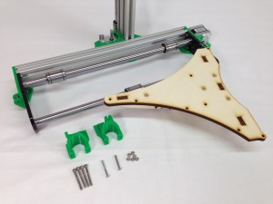 |
| Push the two bearings on the back Y rod to the extreme ends of the carriage. This gives you the space you need to mount the y-carriage. |
 |
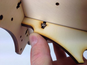
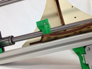
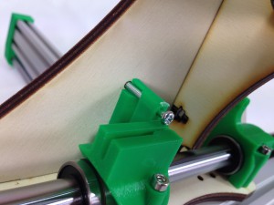
| Take an M3x30mm cap head screw, and thread it through the lower hole of the y-bearing-clamp. Note the orientation of the y-bearing-clamp in the picture. Using a pair of pliers (or fingers if they are small enough!) with an M3 nut, mount the clamp on the y-carriage, around the back smooth rod, as shown. |
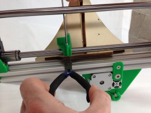 |
| This can be quite fiddly! But it’s much easier without the bearings in the y-bearing-clamps. Lightly tighten the screw, as it will be easier to push the bearing in. |
 |
| Lift the y-carriage up to allow you to hold an M3 nut in position, with pliers, to fix another M3x30mm cap head screw through the top hole in the y-bearing-mount. |
 |
| Repeat the process for the y-bearing-mount on the other side, noting the orientation. Slide the back bearings into the y-bearing-clamps. |
 |
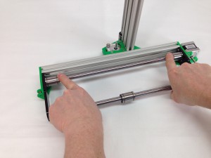
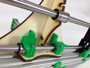
| Note the position of the mount on the bearing. This is important to allow maximum movement of the Y axis in its frame. Slide the front bearing sideways into the notch in the Y carriage. |
 |
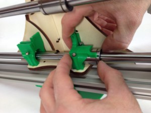
| Using the M3x26mm crosshead screw your removed from the y-axis NEMA17 motor, push this up through the y-bearing-clamp-. If you put it in from the top, it will get in the way of the belt. |
 |
| Secure with an M3 nut on top of the bed-support. |
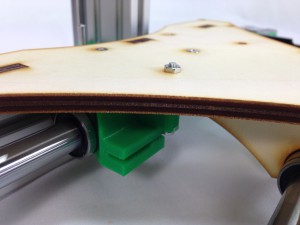 |
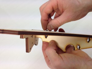
| On the other side, thread a M3x25mm countersunk screw down through the bed-support, through the y-bearing-clamp, and secure with an M3 nut. |
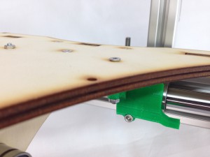 |
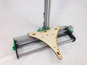
| Tighten all six clamp screws. While doing this, slide the y-carriage up and down the smooth rods; this help centre the bearings, and lets the carriage slide smoothly. The picture shows the finished assembly. |
 |
Y axis drive belt
| # |
Component |
Qty |
Type |
|
1/4″ MXL Belt |
1 |
Hardware |
|
MXL pulley |
1 |
Hardware |
|
M3 grub screw |
1 |
Hardware |
|
Microswitch |
1 |
Electronics |
|
M2.5x10mm cap head screw |
2 |
Electronics |
|
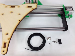 |
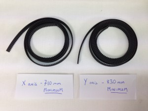
| The 1/4″ MXL belt is supplied as one piece. Measure it with a tape measure, and cut the MXL belt to at least 710mm for the X axis, making sure you have at least 830mm left for the Y axis. There should be more belt than you need, but DO NOT just cut it in half – it may leave with you with too little for the Y axis! |
 |
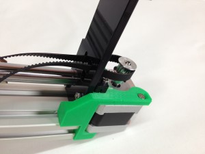
| Mount the microswitch with the two M2.5x10mm cap head screws. These should self-tap into the plastic of the y-motor-mount. Do not widen these holes with a drill, or the screws won’t hold. |
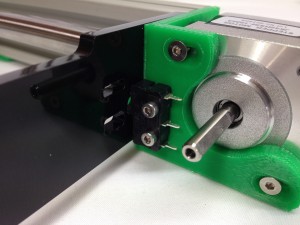 |
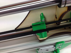
| The switch should align with the hole in the laser cut y-axis-end-plate. Check the tab on the y-bearing-clamp hits the switch at the end of its travel. |
 |
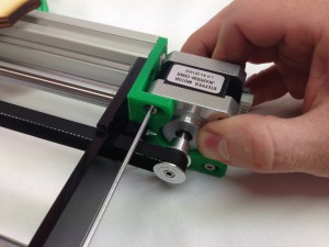
| Screw the grub screw partially into the pulley. The motor shaft has a flat on it; align the grub screw with this. |
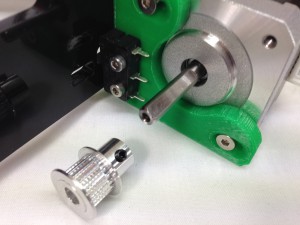 |
| Put the pulley on the motor shaft, and tighten the grub screw using a 1.5mm Allen key. |
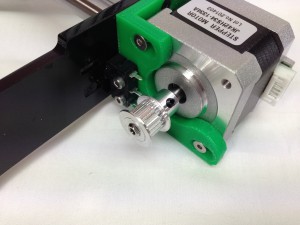 |
| Thread the belt through the top hole in the y-axis-end-plate, around the drive pulley, and back through the lower slot in the y-axis-end-plate. The teeth of the belt should mesh with the teeth of the pulley. |
 |
| Thread the belt along the length of the Y axis. Twist the belt 180 degrees before feeding it through the through the lower slot in the idler end y-axis-end-plate, around the bearing, and back through the top slot. The twist in the belt means it will run on the bearing on the back of the belt. |
 |
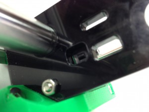
| The twist in the belt also means the teeth of the belt can interlock. This is used to join the belt, and fix it to the y-carriage. Pull the belt tight, interlock the teeth, then push the two belt ends into the y-bearing-clamp, as shown. |
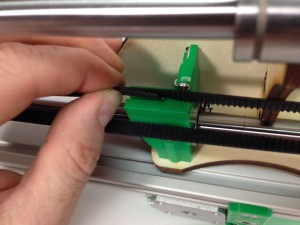 |
| One end of the belt should finish in the clamp, while any extra belt is free to come out the end of the clamp. Adjust the belt until it is as tight as possible. It will probably still be a little loose; don’t worry, you will be able to adjust the tension. |
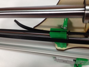 |
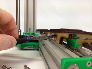
| Cut off the excess belt. Leave about 10mm projecting; you may need to remove and re-fit it one day. |
 |
Y belt tensioning
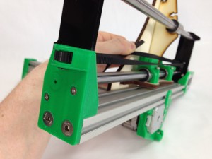
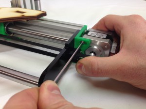
| The belt tension needs to be quite tight, or the axis will suffer from backlash, and you will not get smooth vertical walls in your prints. But the belt should not be too tight, or the motor will struggle to move the axis! To adjust the belt tension, the y-axis motor is mounted in slots. Loosen the three screws, and pull the motor away from the mount to increase the belt tension. Re-tighten the screws, keeping the motor square to the axis. It is sometimes easier to get someone to help you with this, as more than two hands are useful. |
 |
| When you twang the bottom belt, which has the longest uninterrupted span, a just-audible note should be heard. For reference, the note of the lowest string of a bass guitar is suitable. This is the bottom ‘E’ string; search online for another audio example for reference, if you need it. Adjust the belt as required. |
 |
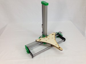
| The completed assembly. |
 |


