
A Project to create open-source 3D printed 6 DoF input devices
Following a discussion on Twitter the general consensus was that a 3D-printed open-source spacemouse that anyone could make would be a good idea. These are used for input to CAD systems such as FreeCAD. It would also be useful (possibly in modified form) for gaming.
So we set up a repository in our Github space to hold designs, documentation and experiments. Others have forked the repository and made contributions, which we have merged in. We hope that more than one design will emerge to allow a certain amount of Darwinian competition.
This blog post is a progress report on one sensor for the device. Ultimately we’ll need six of these, of course.
How far have we got?
 |
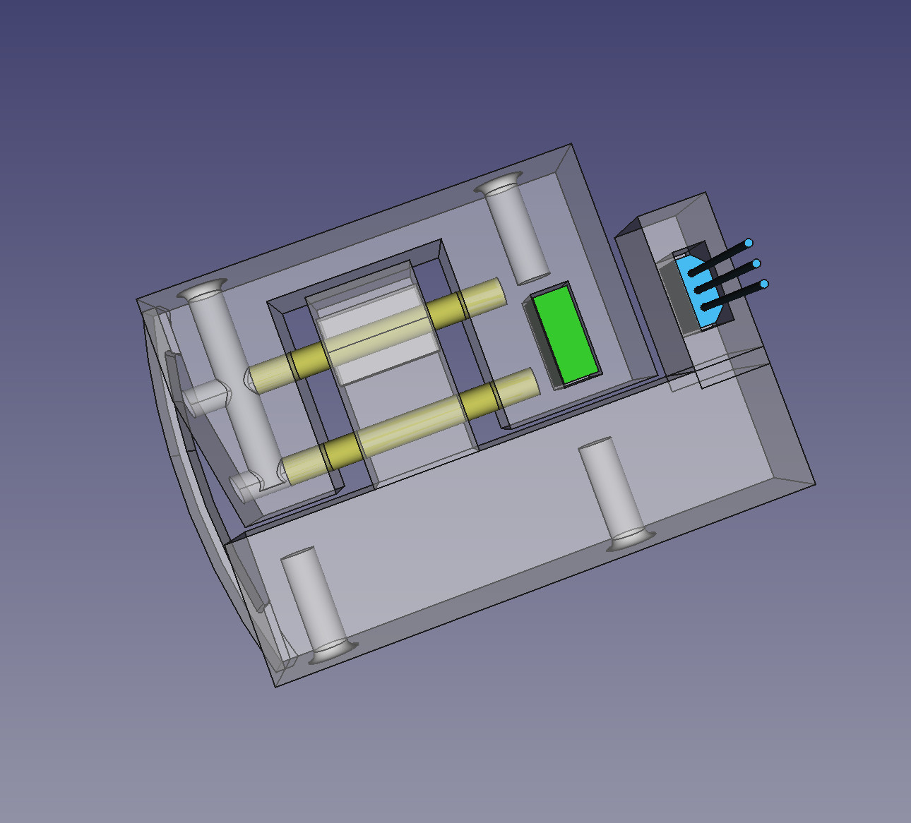 |
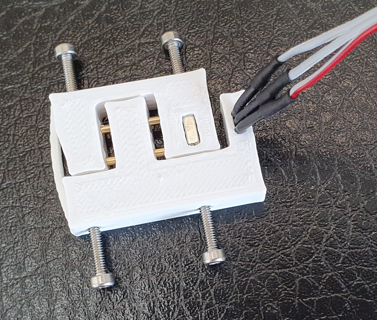
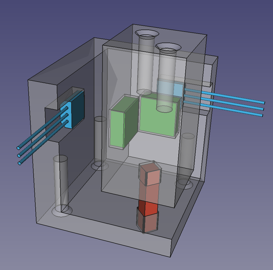
Based on our experiments on our original force-sensor design we have created a new force sensor illustrated above. It works using a magnet and the Hall effect to measure small changes in distance as a spring is bent.
The actual device is on the left and the FreeCAD design is on the right. It consists of a printed part with two 1.5 mm x 15 mm brass rods inserted into holes to act as sliders. On the right the magnet is shown green, and the Hall sensor is blue. The curved part at the left end of the sensor is a printed spring. The four holes in the sides allow self-tapping M2 screws to be used to attach the force sensor to whatever is pushing and pulling it. The top left screw is longer than the others as it also retains the brass rods.
The FreeCAD design is here.
As in our preliminary experiments, the magnets were these, and the Hall sensors were OH49E s.
This design has the following advantages:
- It has just one integrated printed part,
- It gives true parallel motion, with no other movement or twist possible, and
- The additional components are cheap and easy to obtain anywhere.
Experiments
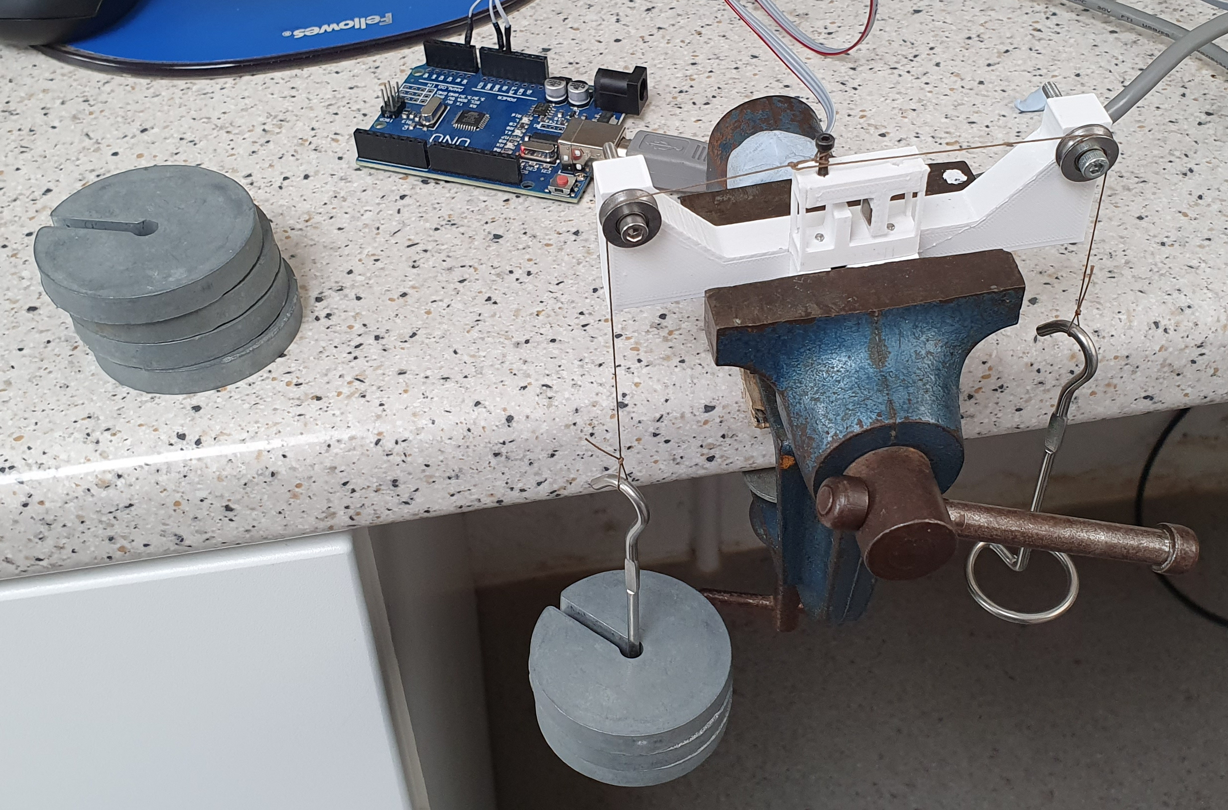
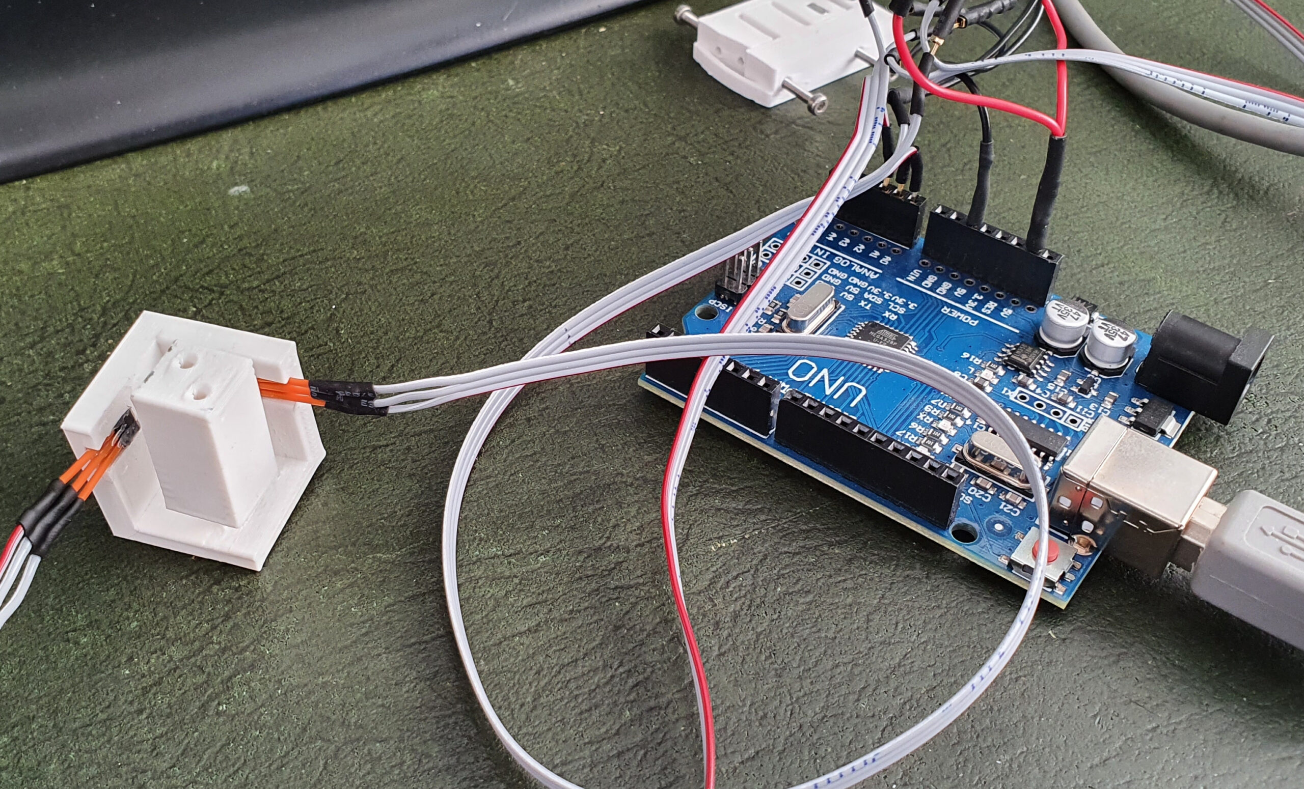
We used a calibration jig based on our design for our first calibration experiments illustrated above. The FreeCAD file for the latest jig is in here.
Here is the result of loading and unloading the device:
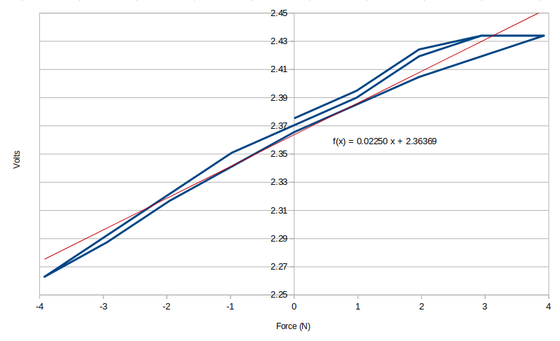
As in our previous experiments, there is a certain amount of hysteresis, as would be expected with a plastic spring. But as you will see this does not impede the performance of the sensor. The red line is the least-squares linear fit, which has the equation shown.
We made two more sensors, giving us three in total. Then we wrote a Python program to read them and to use their output to rotate a cube about the X, Y and Z axes in 3D on the screen. This worked, and the sensor felt good in use; letting go of the sensors stopped the cube moving; pushing and pulling rotated the cube in all directions; and the harder the push or pull the faster it moved.
Ultimately we’ll need six integrated degrees of freedom with a single control handle, but we started with just three on the desk. Here is a video of this working:
The Python program is here and the Arduino program that reads the Hall sensor and talks to the Python program is here.
Update
8 June 2021
We realised from the success of this that it would be easy to design a 2D joystick that used the same principles. This is the result:
 |
 |
The actual joystick is on the left and the FreeCAD design (which is here in the repository) is on the right.
As before the magnets are green and the Hall sensors are blue. The central block has a square spring attaching it to the base (red for clarity, but printed like the other two parts). The holes are for self-tapping M2 screws to attach each part of the device to a handle or a solid base.
If you make one glue the magnets in (Araldite, not cyanoacrylate) with the same pole facing outwards from the sprung block. This is tricky because the fields pull them the other way round and they tend to flip over. Force them right and clamp them while the glue sets.
The device connected to the Python program without modifying that (though it has now been updated to use numpy vector arithmetic for neatness and brevity). It worked well, allowing the cube to be tumbled on the screen as in the video above.
This joystick may form part of the final open-source 3D mouse, but it may also be useful to people in its own right as it is very easy to print and the cost of the components is very small.
Connect with us
Keep up to date on the latest RepRap Ltd news:
Please ensure that this will work equally well left handed as right. Thanks.
The final design will almost certainly be symmetrical so that shouldn’t be a problem. Even if it isn’t, FreeCAD has a mirror function so a left-handed version should be very easy to make.