
This post is about the work in progress on our design of an open-source 3D-printed brushless DC (BLDC) electric motor. These have the advantages of high torque, precise speed control, and no moving electrically connected parts. This is an ongoing project; note particularly that we don’t yet know if it works…
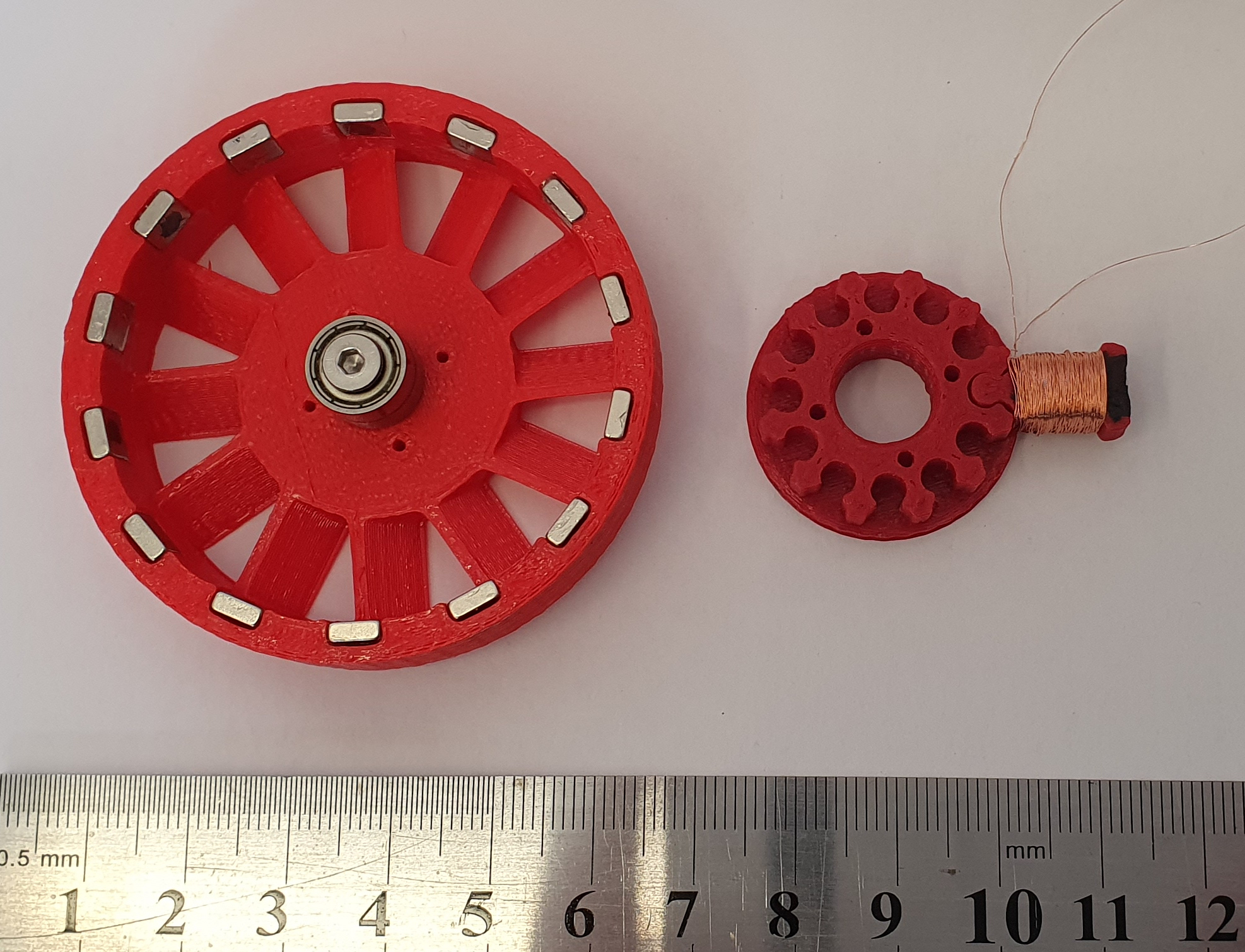
Figure 1
Here is a picture of the structure of the motor from its FreeCAD design:
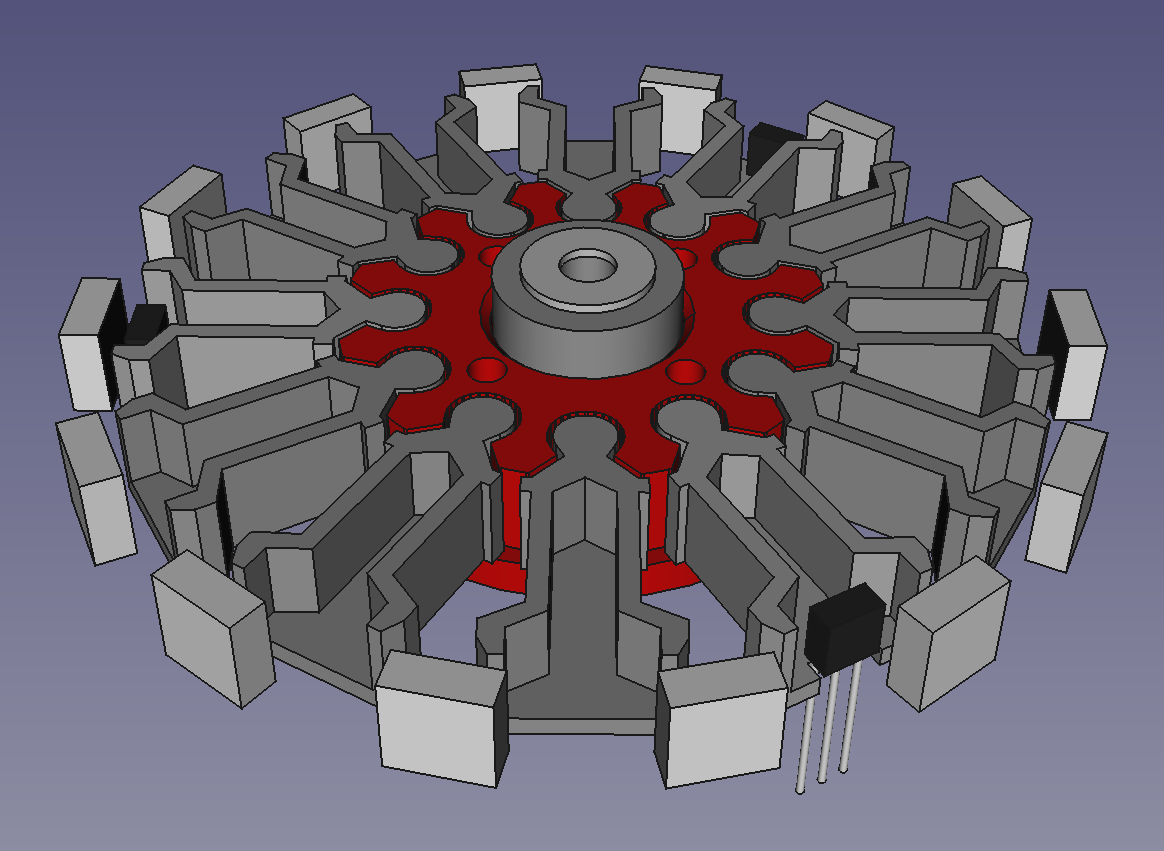
Figure 2
The ring of 14 square blocks round the outside are rotating magnets. The plastic rotor that holds them (the red printed part on the left in Figure 1 above) has been omitted for clarity. The central red hub and the twelve grey radial projections are the stator. The three black blocks are Hall-effect sensors.
Each radial projection will have its central cavity filled with a ferromagnetic paste that will set solid, and will then have a wire coil wrapped around it. It will then be slotted into its position in the central hub. Figure 3 shows an exploded view from underneath, showing the rotor, which incorporates a coil-cooling fan:
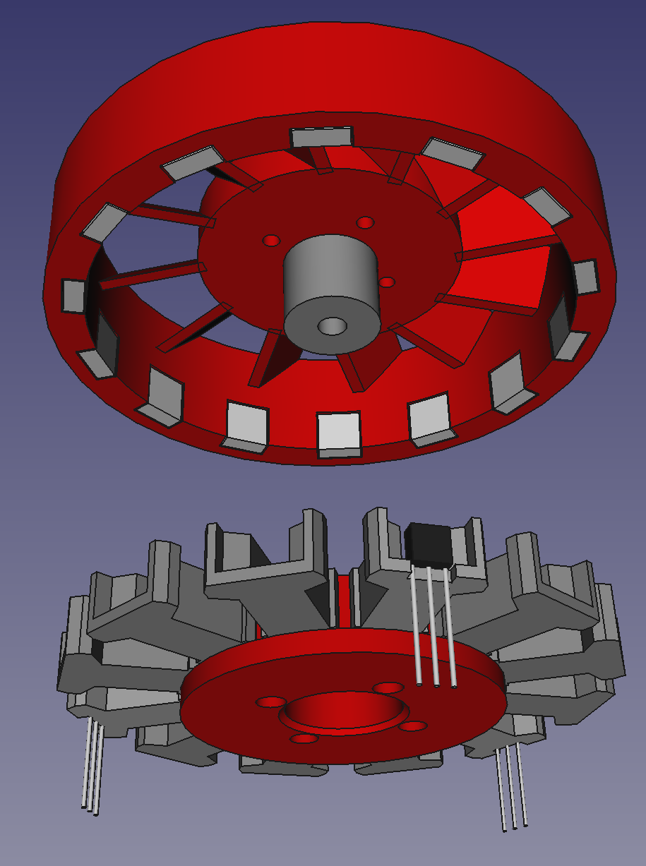
Figure 3
A screw (not shown) holds two stacked 623 bearings to the rotor (the grey cylinder in the middle at the top). These friction-fit in the central hole in the stator.
How was the motor assembled? We started with the rotor magnets, which are 5 x 5 x 2 mm high-strength neodymium ones. If placed near each other they will stack themselves, of course:
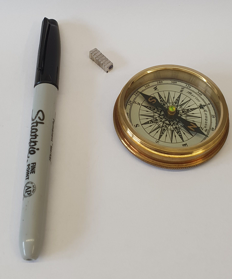
Figure 4
We used a compass to find the North end of the stack, then marked it with a pen. We took that magnet off and went down the stack marking each North pole. (The “S” on a compass is a South pole, and the Earth’s South pole is a North…)
Araldite was then used to glue the magnets into the 3D printed rotor:
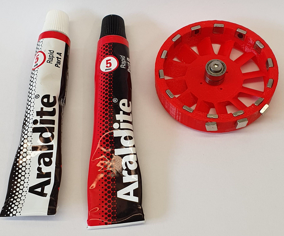
Figure 5
Note that the inward facing poles alternate N-S-N-S-N… This is why we drew the dots. The magnets are so strong that they will tend to pull each other out of their slots when the glue is still liquid. We prevented this by temporarily putting extra magnets round the outside, as shown. We took care to wipe excess glue from the inward facing sides of the magnets to prevent them from fouling the stator, which will move only 0.2 mm away from them. Any glue that remained on the faces was scraped off with a scalpel when the glue had set.
You can see the bearing stack in the middle of the rotor. It is held by a 16mm countersunk M3 screw. There is an M3 washer under the stack against the rotor to allow the outer bearing race to rotate freely without scraping against the rotor.
Next we made the 12 electromagnets for the stator. We started by gluing the three Hall-effect sensors to the slotted radial arms using more Araldite and letting them set. Next we mixed magnetite powder with polyvinyl alcohol (PVA) wood glue to form a stiff magnetic paste (Figure 6):
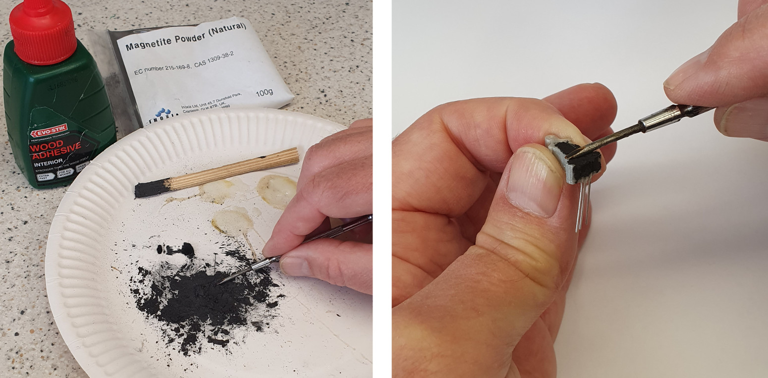
Figure 6 Figure 7
We then put the paste in the slots of the stator arms (Figure 7) and let it set. One of the Hall-effect arms is shown; the paste goes all round the sensor. We took care to ensure that no paste stuck out of the end of the arm (where it would have fouled the rotor). Any that did stick out we removed with a scalpel when the PLA had set.
Next we wound 0.1mm diameter enameled copper wire round each stator arm:
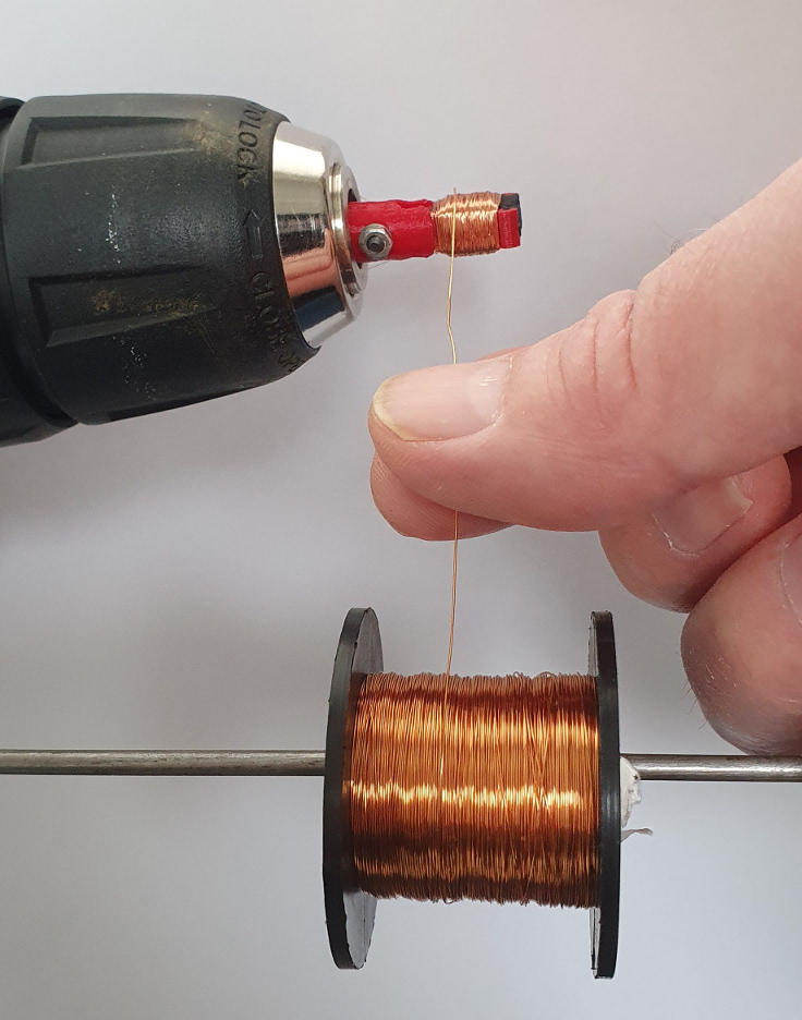
Figure 8
To do this, we printed a clamp for the stator arms that fitted into the chuck of a variable speed electric screwdriver; the clamp design is in the CAD file for the motor. We guided the wire on by hand and stopped winding when we had a 30 ohm length wound on (about 50m). (This stator arm was printed in red as a first shot; we had grey filament in the printer when we printed the rest as shown above.)
Figure 1 at the top of the post shows how far we have got. The next steps are:
- To wind and fit the other coils,
- To wire them together like this, taking care that diagonally opposite coils have opposite poles on their ends:
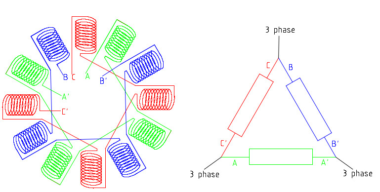 Figure 9 & 10
- To connect up a controller like the L6235 3-phase motor driver and see if it works…
All the files for this project are here on Github.
Adrian Bowyer
Connect with us
Keep up to date on the latest RepRap Ltd news:
Did this work? I am thinking similar to connect to a turbine blade to rotate
Yes – it would certainly generate AC if you span it. It might not be as efficient as a purpose designed alternator, though.
I’m afraid we still haven’t got round to trying it yet. I decided to redesign it so that the coils were aligned axially rather than radially, but I’m afraid I haven’t had time to do that either. All the details are on Github though: https://github.com/RepRapLtd/RobotComponents/tree/main/Printed-BLDC-motor
Do yoy think it is possible to use as current generator ? I think a micro wind turbine stackable motors.
Have you considered using wire rope for stator? Your design would obviously change so you can wind the wire rope.. disadvantage would be winding the magnet wire..
One feedback on your current design is that you’d need to connect each arm of your stator with magnetite as well.. to ensure a continuous magnetic circuit and ensure a stronger electromagnet – so your central hub needs to be magnetic as well.