
The idea for this work and this blog post came from Youtuber Skyentific. So hat-tip to him, and do take a look at his channel.
Ravigneaux epicyclic gears are a compact way to make a gearbox with a large reduction ratio and a corresponding large increase in torque. Let’s start with an explanation of how they work.
To begin with, forget gear teeth and imagine you have a set of cylinders rolling against each other without slipping. Here is a simple epicyclic gearbox represented in this way:
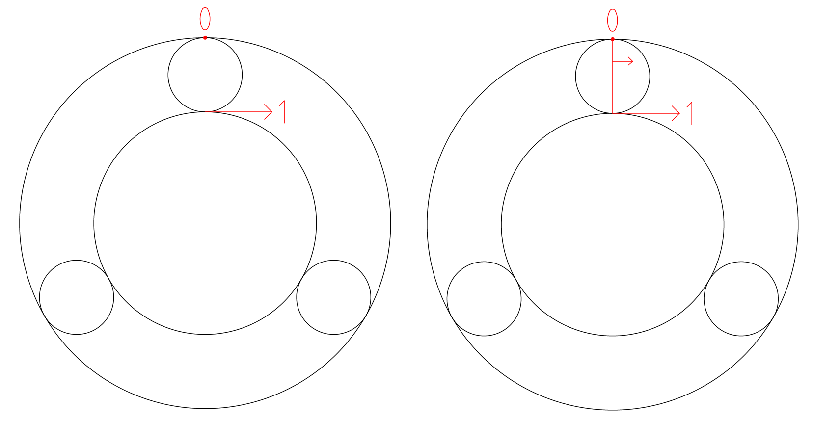
Imagine the central sun cylinder is rotating such that its periphery is moving with velocity 1, and the outer cylindrical ring is fixed (hence the 0) – Figure 1. The small planet cylinders are rolling between the sun and the outer ring. Now, in Figure 2 see the red diameter across the top small planet cylinder. Clearly the end of the diameter that touches the sun is moving at velocity 1, and the outer end isn’t moving at all. By a similar triangles argument, as you track along the red line from the sun to the outside, the instantaneous velocity reduces linearly from 1 to 0.
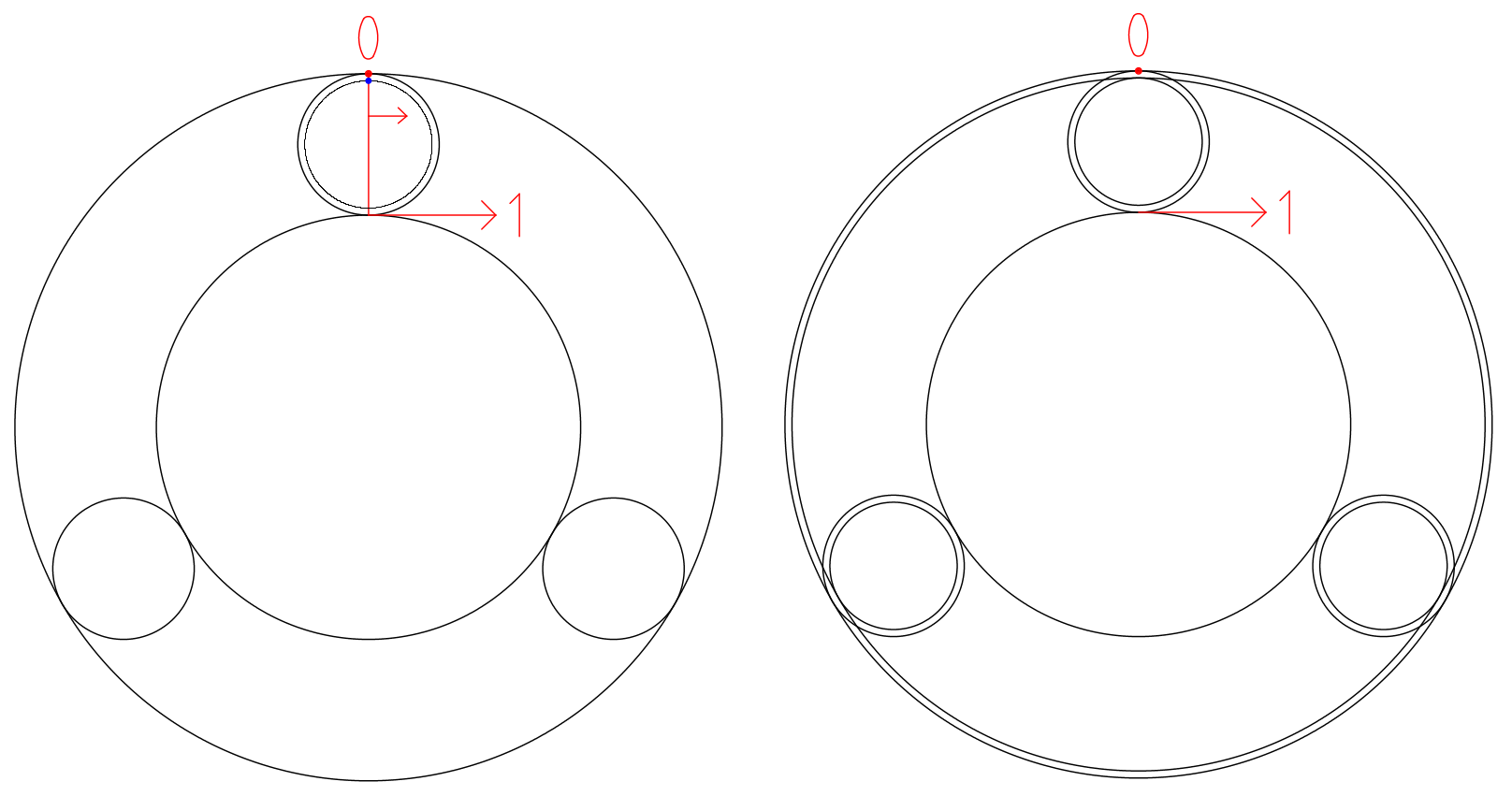
As you approach the 0 end (at the blue dot in Figure 3) the velocity is very small. Stack another planet cylinder slightly smaller than the original planet cylinder on top of the original as shown in Figure 4. The new cylinder’s periphery goes through that blue dot. Do the same for the other planets, then add an outer ring slightly smaller than the original ring that just touches the smaller planets. The new ring is also stacked above the original one.
That new outer ring will now be moving at the speed of the blue dot, which is to say very slowly. Suppose the red diameter line is D long, and the blue dot is x away from the 0 point. The blue dot and the smaller outer ring will be moving at a velocity of x/D.
Now for some teeth. The diameter of the new smaller planet is D – 2x, so the ratio of the smaller to the larger planets’ circumferences will be (D – 2x)/D (the πs cancel). To put some numbers in to make things clearer, suppose D = 25, and x = 0.5. We now have a ratio of circumferences of 24/25. So lets put 24 teeth on the smaller planet, 25 on the bigger one, and whatever numbers of teeth on the sun and the two outer rings that are needed to mesh. We will have made a gearbox where driving the sun, and taking the output from the smaller ring, gives a ratio of x/D = 0.5/25, which is to say 1:50. The smaller outer ring will rotate 50 times slower than the sun gear, with 50 times more torque (ignoring friction losses).
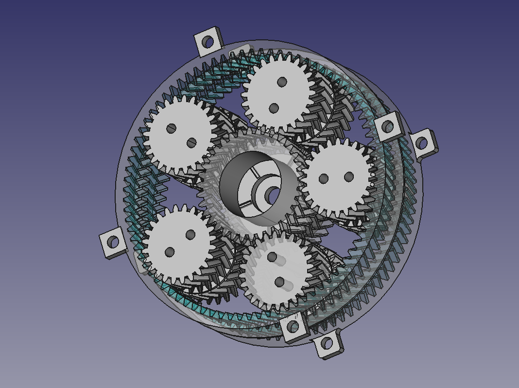
Sally has designed and 3D-printed a set of gears to experiment with this idea. You can have any number of planets greater than or equal to three, as long as they don’t collide with each other. The more you have, the better the rigidity and alignment, but also the greater the friction. We chose five planets. An odd number seemed better to Sally than even, to prevent two planets being exactly opposite each other and so possibly increasing internal stresses.
Here are the stacked larger and smaller planet gears, which are made in three parts:
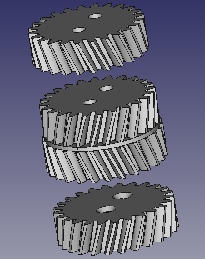
We need herringbone gears to prevent the whole gearbox sliding apart along its primary axis. But printing all the gears as single herringbone solids would make the gearbox impossible to assemble. (Though there is the potential to 3D print the whole gear box as one….) This stack of three allows assembly by sliding. The three parts of each planet gear are then screwed together down the two holes you can see. The holes in the top two parts are clearance holes, and in the bottom part are smaller to allow self-tapping. The chamfer is to make the self-tapping easier to start. When assembling the gearbox it helps to put it on a lightbox so you can align the pairs of holes. The disc in the centre of the central part is to separate the top and bottom outer rings by a small distance so that they do not rub against each other.
Here is a video of the gearbox working. The slight wobble is not caused by the gears, but is caused by the bolt that we put through the central sun gear not being quite aligned with its axis – we need to make the hole for the bolt longer.
As you can see, this first design can easily be driven by an electric drill. But it is too stiff to work with a smaller motor. That could partly be addressed by lubricating the gears with silicone grease, but we also need to increase the clearances slightly. We may use the Minkowski technique we described last week to do that.
You can find the files for this experimental open-source design on Github here.
Future plans for this project are:
- To align the central shaft properly to eliminate the wobble,
- To lubricate the gears…,
- To increase the clearances as just described,
- To fit a brushless DC motor inside the sun gear to drive the whole gearbox, and
- To figure out how to fit an Austria Microsystems Hall-effect absolute rotary encoder to the slow output ring so the whole thing can be used as a servo.
Sally & Adrian Bowyer
Connect with us
Keep up to date on the latest RepRap Ltd news: