
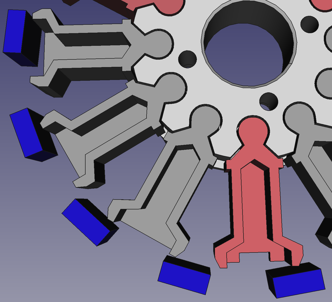
It’s often the case that you need to 3D-print objects that must slot together, like the grey and red parts slotting into the white central hub in the picture above. (It’s a design for a 3D-printed BLDC motor that we’re working on – more on that later this month.) As with traditional manufacturing, you can’t make the slots the same size as the thing that has to go in them, otherwise the result will be too tight to assemble. So what you need in the CAD system is a slightly larger version of those things to subtract to make the slot.
You can just design a bigger version, of course, but that’s a lot of tedious extra effort. Or you can try to scale the thing to be subtracted to make it bigger; but that seldom works as it magnifies larger dimensions by a bigger distance than smaller ones. What you need is a version of the thing to be subtracted that is uniformly 0.1 mm (or whatever) bigger than the original. Such an object is an example of the Minkowski sum operator of set theory.
Imagine that you take one of the grey shapes that you want a slot for, and a sphere of 0.1mm radius. Now let the centre of the sphere visit every one of the unaccountably infinite points in the set that represents the grey shape, and take the union of all those infinitely many spheres. The result would be a version of the grey shape that was 0.1mm bigger in every direction. This is exactly what you want to subtract to make the slot, and it is the Minkowski sum of the grey shape and the sphere.
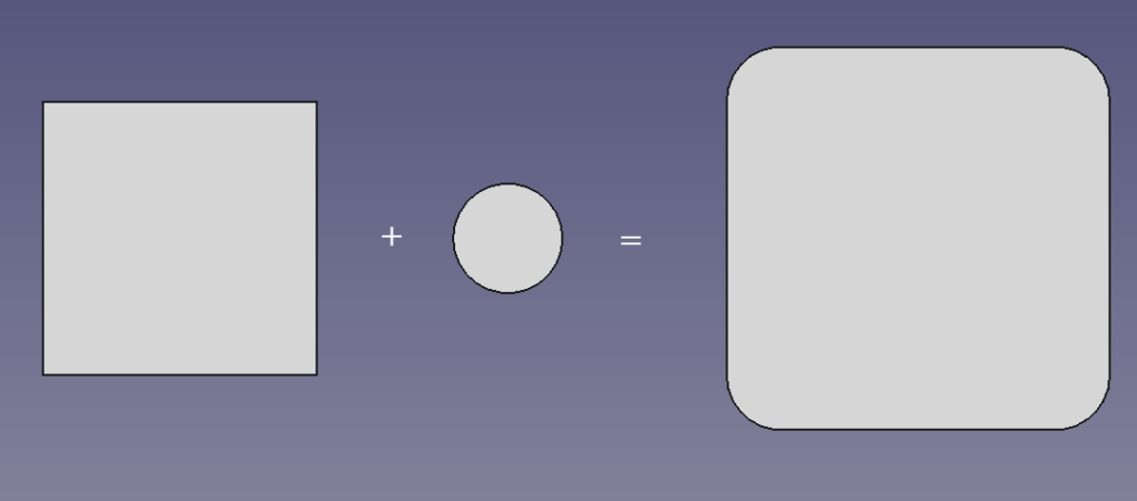
Here is a simpler example in two dimensions rather than three:
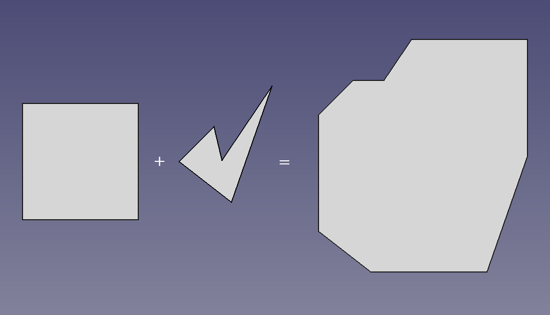
The object you add doesn’t have to be a disc or a sphere; you can take the Minkowski sum of any two shapes:
And the reference point which visits all those infinite other points does not have to be any sort of centre; it can be anywhere (not even within the shape) and the result will be the same shape; it will just be translated to a different position.
The open source CAD system OpenSCAD has a Minkowski calculator. But the examples above were created in the equally open source FreeCAD. Because of all this open source goodness, FreeCAD incorporates aspects of OpenSCAD in itself, and thereby inherits Minkowski sums from OpenSCAD.
Of course, to calculate Minkowski sums the CAD systems don’t do infinitely many operations. They take advantage of the fact that, for example, the Minkowski sums of convex polyhedra can be calculated from just knowing their vertices. However, it is still a computationally quite expensive thing to compute. What does this mean in practice? Well – despite its simplicity, a sphere is a difficult object to work with and will take a long time in Minkowski calculations. The reason is that it has surface normals pointing in every direction. Doing Minkowski sums with discs is a lot faster, and will often work perfectly to solve the problem we started with: offsetting a solid by a fixed amount to allow it to make a slot by subtraction. Taking the Minkowski sum with a little cube will be even quicker, and that may well work to solve your offsetting problem too.
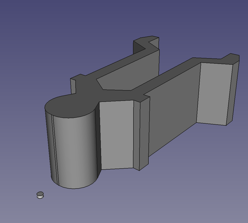
Here is the electric motor example. We start in the Part workbench in FreeCAD and make a small disc (in this case 0.2mm radius and 0.2mm thick) and the shape to be enlarged:
We go to the OpenSCAD workbench, select those two objects, and select Minkowski from the drop-down menu:
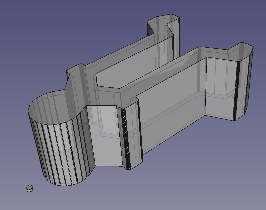
The result is the shape that we need to subtract to make the slot that we want. Here it is shown transparent, with the original object inside so you can see what’s going on. Note that, as a consequence of the computational complexity of computing exact Minkowski sums, the result will have a faceted approximation to any curved surfaces – it’s a lot easier to work exclusively with flat planes. But this doesn’t matter for 3D printing because that uses STL files, which are also faceted anyway.
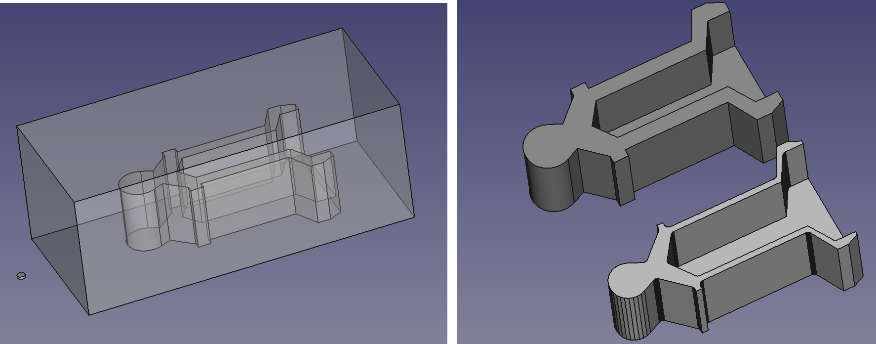
Finally, what do you do if you want to make something uniformly smaller, rather than bigger? You subtract the object from a solid block to make a cavity, you make a Minkowski sum of that block and cavity with, say, a disc to make the cavity smaller, then you subtract that from another block to make the result you want. Here is the cavity and disc, and the final result in front of the original:
If you are interested in how these ideas can be applied to the automatic analysis of machines and how they move, then see this work done by my postgraduate students and me, which was (I find alarmingly) published over two decades ago…
Adrian Bowyer
Connect with us
Keep up to date on the latest RepRap Ltd news:
One real gotcha with OpenSCAD’s minkowski operator is that if the second argument is offset from the origin, the whole result is shifted by that offset. So if your part is in a different place after applying this operator, it was probably the offset all along.
Yes, as the blog post says the Minkowski sum can be positioned anywhere by deciding upon the position of the reference point, which can also be anywhere. If the position of the reference point is known then the result can be translated to a line-up in any way required with the original object.
OpenSCAD also has an offset() module for 2D that is more direct than Minkowski with a disc. As the outside profile is 2D I would model it in 2D before extruding it and subtracting the pocket. I would then offset the 2D profile and extrude it to make the slots.
Yes – I’d do it that way too for extrusions or solids of revolution. But the Minkowski technique is good for more general shapes.