
A characteristic that a lot of 3D printers share is having wires running all over them. These are often neatened in places with cable ties, but they still look scruffy and often get in the way of the machine moving, or you when you want to adjust the machine. In our latest RepRap, Lorenz, we are trying to reduce this problem significantly by running as much of the wiring as possible inside the solid parts of the machine.
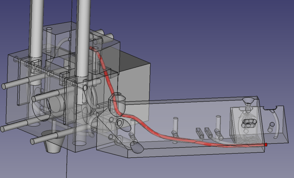
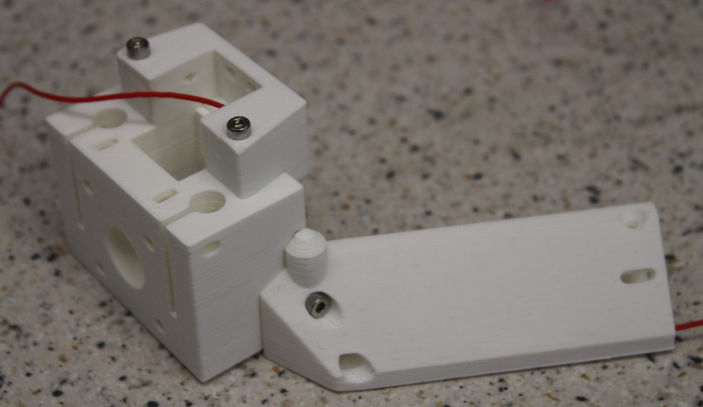
On the left is a transparent picture from the FreeCAD model. The parts are quite complicated, but not so much so that we can’t run a sweep of a 2mm diameter disc along a spline through them to make a hole for a wire. When the parts are printed then bolted together, you just poke the wire in one end of the hole, and it comes out the other.
This particular wire runs in sections round the entire machine, serially linking the bed switches that are used for levelling (an elegant system taken from Jean-Marc Giacalone’s Fisher RepRap).
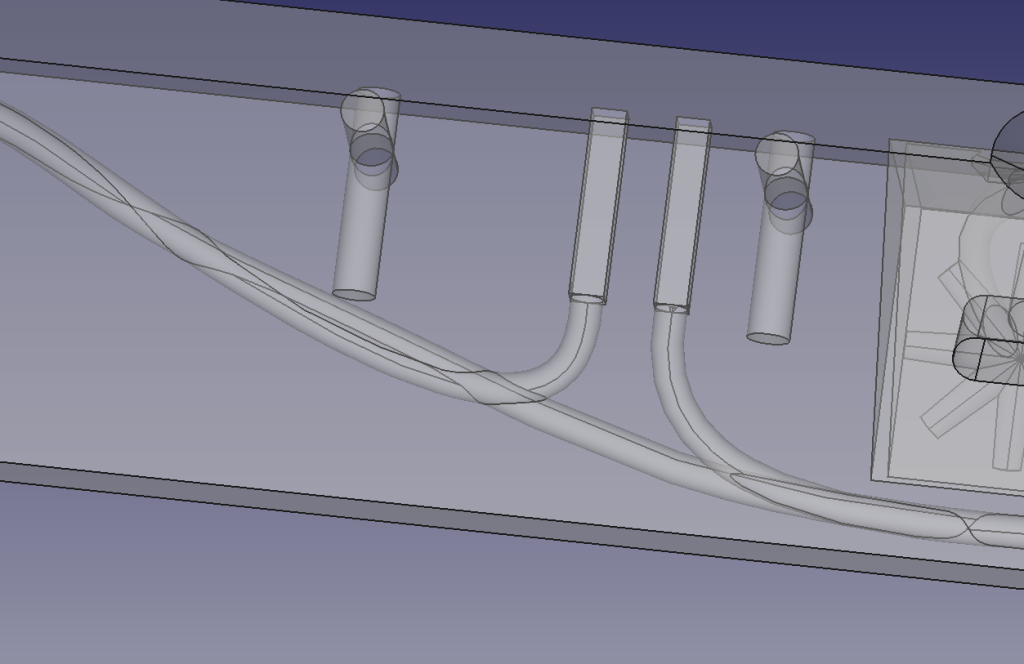
We also need to make connections to the switches at one point in the loop, so you can see that the sweep forks twice inside the prismatic part and leads to two thin square holes. These house crimp connectors and are on a 5.08 mm pitch. They form a standard socket that short wires can plug into to connect to the controller.
To create the spline I move a point (well, an 0.2mm cube) around inside the design recording points along it in a simple Python macro that generates a curve in space;
import Part
c=Part.BSplineCurve()
from FreeCAD import Base
pts=[
 Base.Vector(-8, -8, -249),
 Base.Vector(-8, -13, -250),
 Base.Vector(-8, -16, -252),
 Base.Vector(-8, -25, -266),
 Base.Vector(-8, -28, -270),
 Base.Vector(-9, -34, -282),
 Base.Vector(-15, -37, -284),
 Base.Vector(-24, -46, -293),
 Base.Vector(-36, -60, -296),
 Base.Vector(-47, -72, -298),
 Base.Vector(-63, -83.5, -298.5),
 Base.Vector(-73, -89, -298.5)
 ]
pts
c.interpolate(pts)
s=c.toShape()
Part.show(s)
It’s important to avoid sharp bends in the spline, otherwise the wire will jam when you try to feed it through the hole. The FreeCAD sweep function then generates a solid which is subtracted from the parts to make the tube along which the wires run. Note that this solid is exactly the shape required to dual-print in an electrical conductor like this to replace the wire when everything is proven.
As mentioned in the last post, where no printing runs, like up the vertical axis of the machine, we make the sliding rods tubes and run services (the Bowden extruder feed as well as wires) up them. We also use the tubes themselves as electrical conductors, in this case connected to the endstop microswitches. These connections are, of course, made using further buried wires. In this case those wires emerge inside the tube clamps in the clamping part itself. This ensures that the thickness of the wire contacting the tube does not alter its position.
Adrian
Connect with us
Keep up to date on the latest RepRap Ltd news:
Pingback:RepRap Lorenz's First Test | RepRap Ltd