
Using electroplating we have coated a section of a 3D print in copper.
To do this we cleaned up a scrap piece of copper pipe with wire wool. The tube was connected up to the positive side of the power supply and was submerged it in copper sulphate solution. This then became the anode.
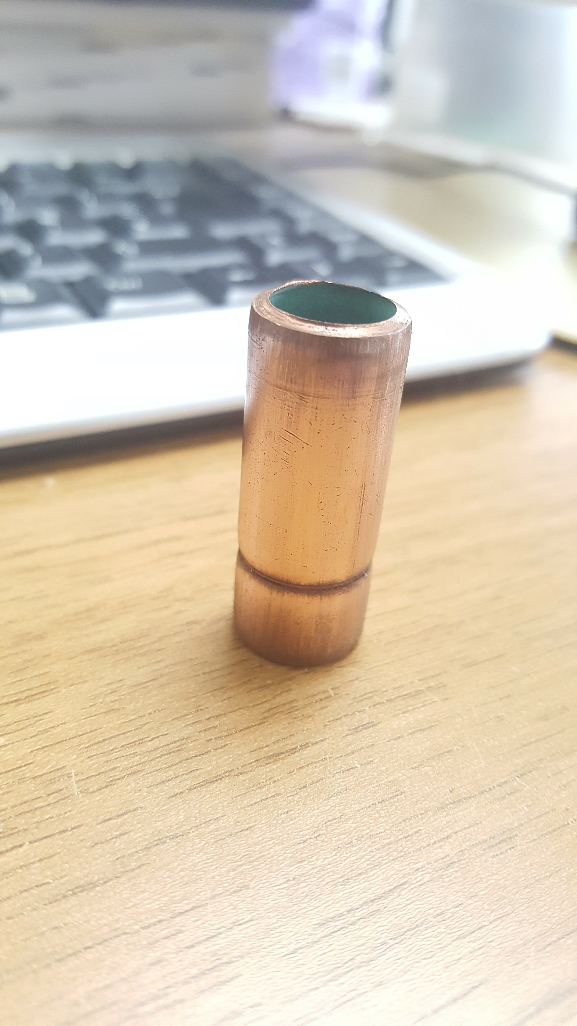
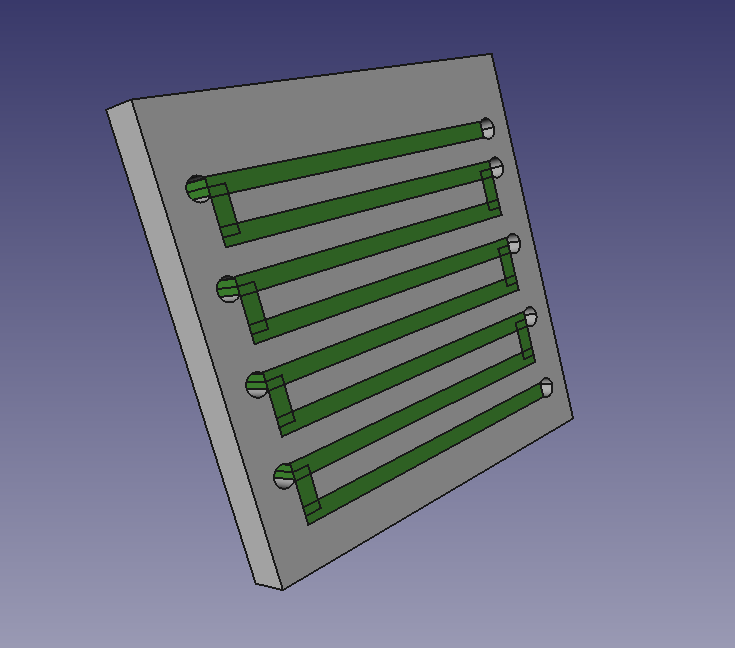
The 3D print was created in PLA (insulator) and F-Electric PLA (conductor) on our dual-head Ormerod. The print was created with holes to attach wires to the conducting filament. We needed fat multi-strand wire to make good contact, so we used speaker cable.
This wire was then connected to the negative side of the power supply making the printed F-Electric the cathode and the 3D print was submerged in the CuSO4 solution (with a bit of extra H2SO4). The power was then applied.
Initially the wire connecting to the 3D print were submerged in the copper sulphate solution. The wires being copper had very high conductivity, so most of the current was going into the solution via them. So a large amount of copper was being deposited around the wires rather than on the conducting part of the 3D print.
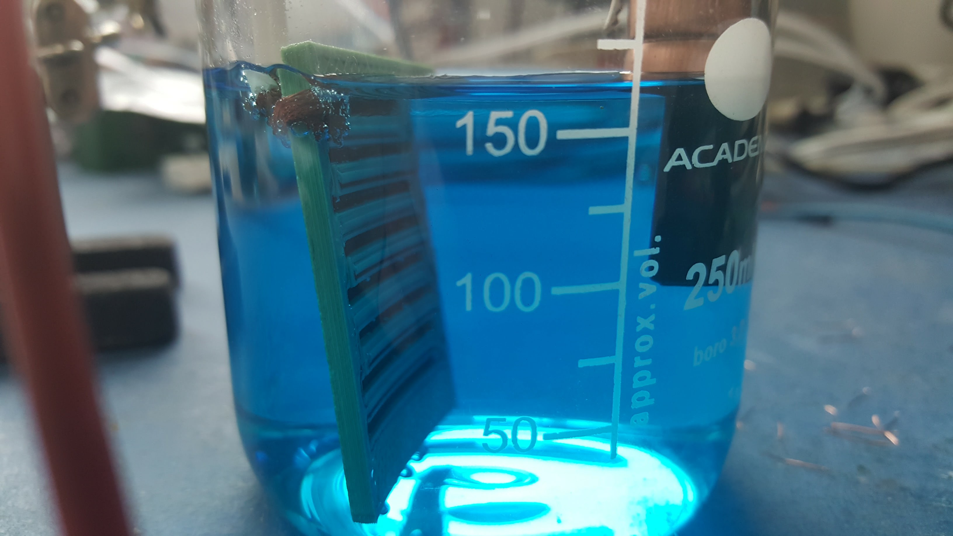
The experiment was paused and the excess copper was knocked off the connecting wire. Two new wires were then connected to the F-Electric part of the print and kept above the solution when the 3D print was returned to the solution. Copper then started to build up around the F-Electric PLA.
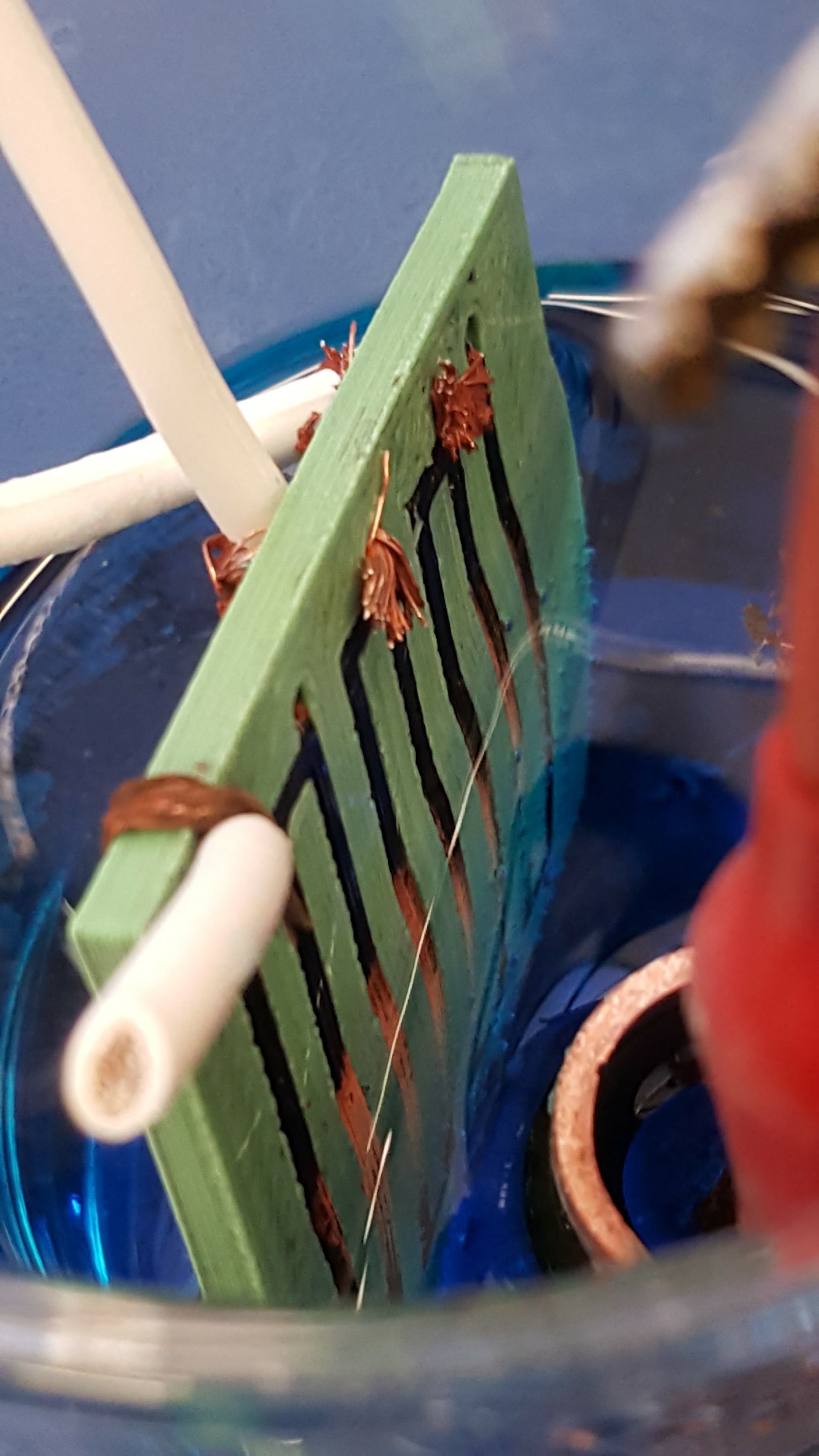
After about 5 hours the copper pipe had disintegrated so we switched off the power and removed everything from the solution.
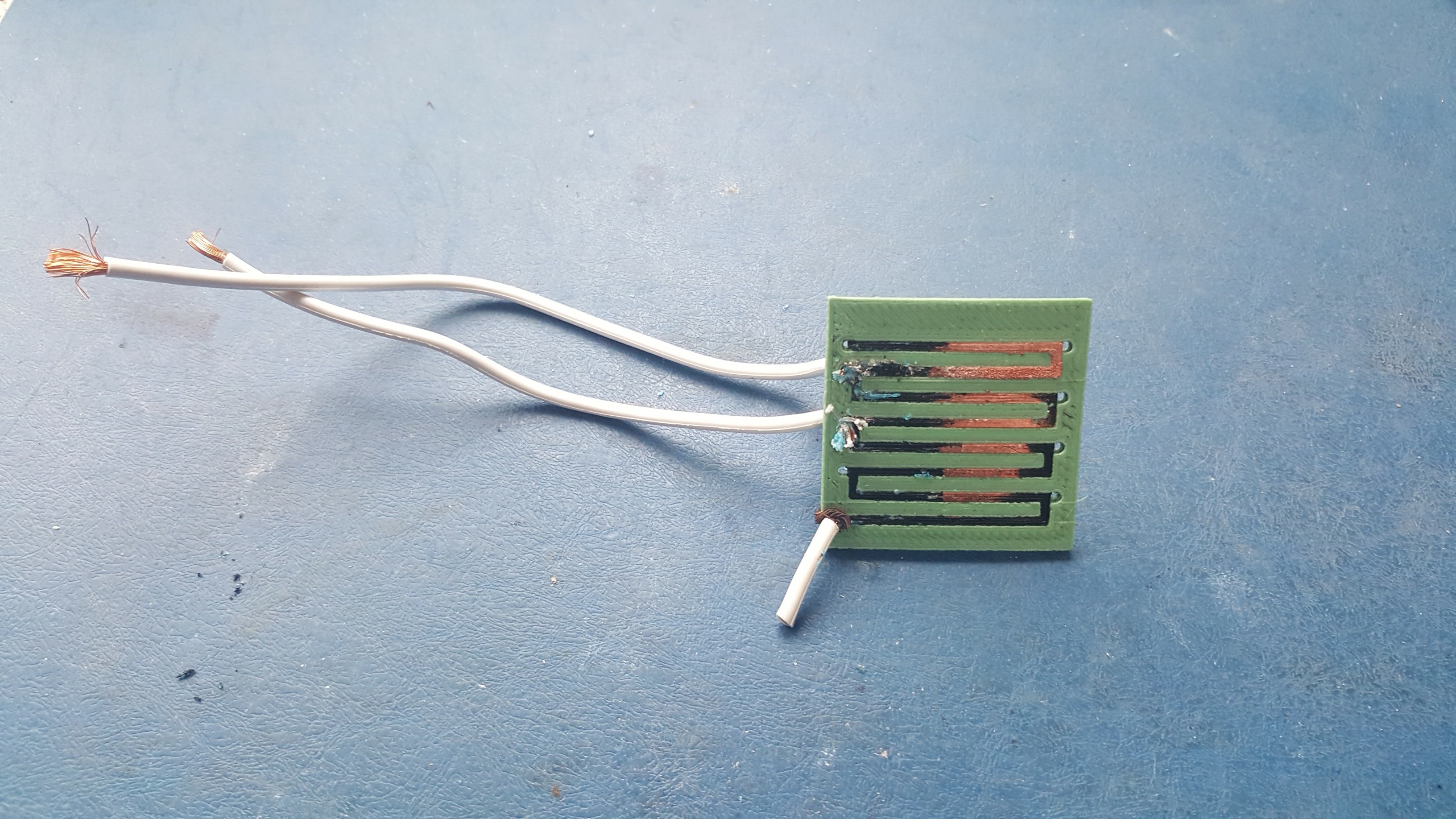
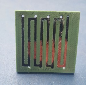
The end results:
Adrian says:
The F-Electric has very good low resistivity for an electrically-conducting polymer. But the effects of its resistance can be seen in the uneven distribution of the coating. One approach may be to reduce the concentration of the copper sulphate solution to raise its resistance. The two should then be better matched, leading to a more uniform coating. It will be slower, of course, but this isn’t time critical.
After that we will try an alternative. We will dissolve some F-Electric in DiChloroMethane (good ventilation needed) and paint it on a 3D-printed part to see if we can copper-plate the entire surface. This is the equivalent of painting glue on a part then covering it in graphite, which others have done. If this works, we will try using the F-Electric just for the outer layer of the print, with ordinary PLA inside.
Connect with us
Keep up to date on the latest RepRap Ltd news:
Hi,
This is extremely interesting !
Am I extrapolating too much or one could imagine making PCBs with circuit tracks as thin as the printing nozzle consents ?
What about soldering components ? the underlying PLA would badly suffer !?
Best regards,
Gad
Yes – you could certainly do PCBs this way with highly conducting tracks. You could have tracks bridging over others supported by ordinary PLA too. One problem is that you have to make a connection to all the tracks to plate them, but for a PCB they will be separate parts of the circuit. You might be able to solve that by creating snap-out connecting sections that get removed when the plating is finished.
And you could probably solder onto the tracks without causing too much damage (we’ll try that soon). Metals have a much lower specific heat than plastics (about a third), and much higher thermal conductivity of course, so with luck any melting should be local.
Just tried the soldering. Turned out to be trickier than we thought. For some reason the solder would not wet the copper (with flux, or without). Though trying to do it did not destroy the underlying plastic. More experiments needed…
My recollection of commercial electroplating is that the often use several layers of different metals before the final metal in order to produce a better result (or even a result).
I won’t claim to have any understanding of the chemistry behind this but they seem to find it important.
Perhaps then you need some other metal first???
Yes – you may well be right. Indeed I think copper is sometimes used as such a precursor for other metals. There are also zinc and nickel. As always an experiment opens the path to many more experiments…
Dear Sir,
I’m a student of the University of Montpellier in France and I’m currently in an internship. I’m very interrested by your work on electroplating 3D prints. I would like to know please if you have pursued the study and try to paint some F-Electric on a 3D printed part.
Best Regards,
Fadel ABDEL KADER.
Hello Fadel Abdel Kader!
I’m afraid that we have not had time to do further experiments on this. But Sally found that the key thing is electrical resistance. When you start plating the high resistance of the polymer means that the part gets preferentially plated near where the electrical connections are made. Because the plating has low resistance, this effect is subject to positive feedback. The solution is to make multiple connections to the part to be plated all over its surface if you can. You can often design in tabs that will be later removed to make connections to. Hope that helps.
Best wishes
Adrian
Thank you very much. It helps me a lot.
Have a good day.
Fadel.