Contents
- 1 Printing the plastic parts
- 2 Attach the end-bearings
- 3 Build the screw-drive
- 4 Build the motor drive
- 5 Put the syringe drive together
- 6 Attach the power-supply mounting bracket
- 7 Attach the paste extruder to your Ormerod 2
- 8 Attach the motor cable
- 9 Try a syringe and the top strengthener for fit
- 10 Build the nozzle tubes
Printing the plastic parts
If you have bought the full kit for the Paste extruder including the printed parts, please skip to the next section.
For the hardware-only kit start by downloading the design files from our Github repository here. Bottom right on that page you will see a “Download ZIP” button which will give you a compressed archive of all the files.
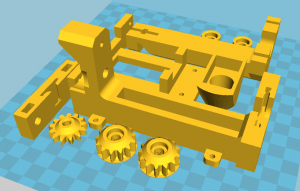
There is a folder in the archive called Printed-parts and a single STL file in that folder called paste-extruder-all-parts.stl. Print that on your Ormerod. We use a layer height of 0.2mm with an 0.5mm nozzle, two perimeters, and an infill density of 40%.
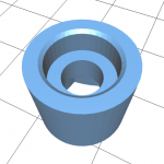
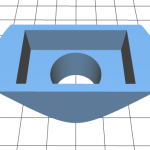
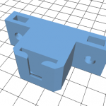
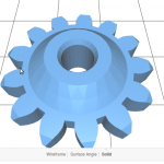
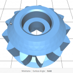
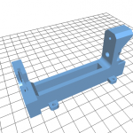
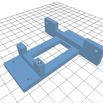
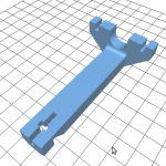
Here is a list of the parts that will result:
Note that the gears are exactly the same ones that are also used for the Ormerod 2 Z drive.
Attach the end-bearings
You will need the following parts:
|
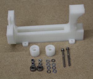 |
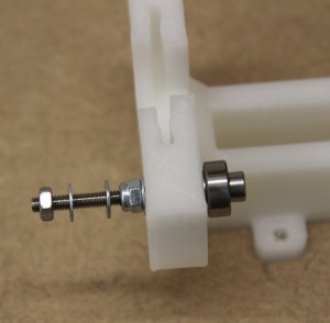
Attach the bearing to the frame as shown. From the right in the picture the order is:
Washers are stamped from sheet steel, which means that their faces are slightly different if you look closely – one is rounded (the bottom of the stamp) and the other has sharp edges (the top of the stamp). Make sure the rounded face of the washer is against the bearing. The orientation of the other washers doesn’t matter. |
 |
| Attach the bearing on the other side of the frame in the same way. Then push the bearing holders over the bearings. Check that they and the bearings rotate freely. | 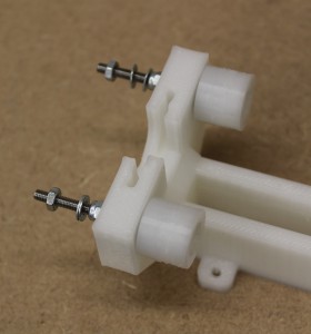 |
Build the screw-drive
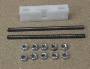
You will need the following parts:
|
 |
Note that the design of the drive block has been improved since these pictures were taken (see the printed parts list at the top of the page for what it now looks like). But the new one is fitted in exactly the same way.
| Put a nut in each nut slot of the block. Screw the bars part-way through. Put pairs of nuts locked against each other on the ends of the bars; tighten them firmly, but don’t strip the threads. Screw the bars through so they are as shown, with one end against the side of the block with the slot. | 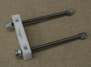 |
Build the motor drive
You will need the following parts:
|
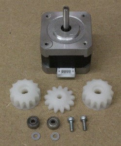 |
Align the flat on the motor’s drive shaft with the flat in the central hole of the drive gear. The bump on the gear should be downwards (as in the picture) facing the front plate of the motor.Push the gear down on the shaft. It should be tight, but not so tight that the shaft damages the printed gear. If it is hard to push place a small object (an M4 nut works well) under the other end of the motor’s shaft to support it, put a rigid tube on the gear, and tap the end of the tube with a light hammer. Make sure there is a small gap (around 0.5mm) between the bump on the gear and the front plate of the motor. Make sure that the motor can turn freely. Push the bearings into the cylindrical holes in the gears. Then drop the screws through the bearings and screw them to the motor with a washer underneath.This photo shows the screws and bearings without the gears for clarity. From the bottom the order goes:
As above, make sure the rounded faces of the washers are against the bearings. |
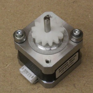 |
| This shows the completed assembly. Check that all three gears and the motor can rotate freely without sticking and without teeth jamming. | 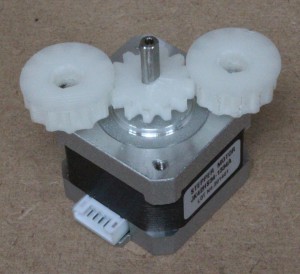 |
Put the syringe drive together
You will need the following parts:
|
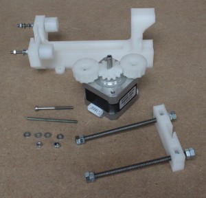 |
| Push the screw drive nuts into the bearing holders. Make sure that both threaded rods can turn freely, then make sure they are at the end of their travel as shown. This is to make sure that the drive block is at right-angles to the threaded rods. | 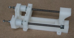 |
| Push the gears on the motor over the nuts at the other end of the threaded rods. You may have to turn one of the rods a little to align its nuts with the hole in its gear. This is to be expected. | 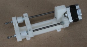 |
| Secure the motor with the cap screw and one of the washers (furthest away in this picture) and with the threaded rod, a washer and the nyloc nut (nearest in this picture). | 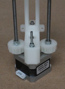 |
| Put two more washers on the threaded rod and a washer on the end, as shown.Turn the gears by hand (don’t pinch your finger) and check that everything rotates freely and that the drive block moves backwards and forwards. | 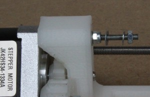 |
Attach the power-supply mounting bracket
You will need the following parts:
|
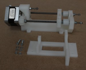 |
| Use the screws washers and nuts to attach the mount to the bottom of the frame as shown. Just two fixings on a diagonal are needed (though there are four holes provided). The larger cross-piece goes furthest from the motor. | 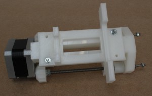 |
Attach the paste extruder to your Ormerod 2
You will need the following parts:
|
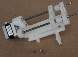 |
| Use the screws and washers to attach the paste extruder to the top of the power supply of the Ormerod 2. There are two threaded holes in the supply that match the holes in the mounting bracket. | 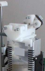 |
Attach the motor cable
You will need the following parts:
|
 |
| Important: when unplugging and plugging in any RepRap electronic devices first make sure that all power is disconnected including the USB cable.
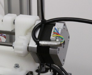
Plug the cable into the motor and use cable ties to give strain relief as shown. Make sure that the cable does not foul the gears. Pull the cable ties tight then clip off their flying ends. |
 |
| If you want to print paste on its own without plastic, unplug your existing extruder drive stepper motor from your Duet and plug the paste extruder motor in its place.
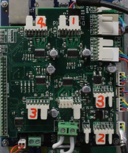
If you want to print plastic and paste in the same print you will need a Duet Shield. If it is not already present, attach the Duet Shield to the Duet controller of your Ormerod. Instructions for that are here.Plug the other end of the cable into a spare motor drive socket on the Duet Shield. The picture shows it plugged into Drive 1 of the new four-drive Shield, but any drive on either the two- or the four-drive Shield will do. |
 |
Try a syringe and the top strengthener for fit
| Turn the gears by hand to place the drive block about half-way along its travel. Adjust the position of the plunger in a syringe to match the slots in the drive block and the front of the extruder drive. Make sure that the four cross webs of the syringe plunger are at 45o to the horizontal and vertical. Push the syringe and its plunger into the slots. | 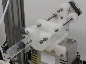 |
| Move the three free nuts with the double washers behind them to the front of their travel. Spread each pair of washers as far as they will go. Drop the top strengthener onto the screw shafts as shown. You will find this easier if you put the end nearest the motor on first. Make sure that there is a washer either side of the plastic of the top strengthener. Tighten the nuts. At the motor end you will need a thin spanner or a pair of needle-nosed pliers to do this.These two operations above and here are what you need to do to load a filled syringe into the device. Unloading is the reverse. To unload the syringe you may need gently to lever its plunger up out of its slot with a screwdriver. Take care not to apply too much force to the rest of the device when you do this. Practice unloading the syringe with this empty one. | 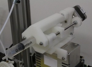 |
Build the nozzle tubes
You will need the following parts:
|
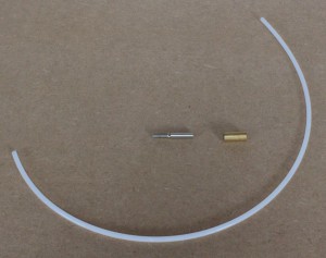 |
One set of parts is shown in the picture; there are two sets with the kit.
| The assembly of the nozzle tube is identical to the assembly of the hot end Bowden tube, instructions for which are here. All you do is to substitute the Luer syringe union for the brass Bowden start. Build two nozzle tubes. |  |
| Using a sharp blade cut the 4mm thread caps to length (about 6 mm) as shown. | 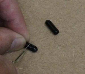 |
If you dismantle the tubes in the future, for example to clean them, then take care to:
- Clean the threads thoroughly while the paste is still wet. A Q-tip is good for this.
- Start the threads carefully when reassembling. You don’t want to cut new threads in the PTFE – this will weaken it.
Whenever a tube is full of paste always put an end-cap on its nozzle, preferably with a couple of drops of water in the end cap to keep the nozzle moist. If you don’t the nozzle will dry and block.

