DRAFT – these instructions are not final, and are likely to change.
Connecting rod assembly
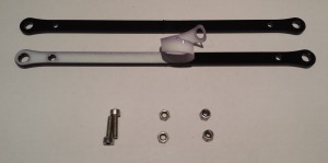
You will need the following parts:
| # |
Component |
Qty |
Type |
| 1232 |
Rod |
12 |
Lasercut |
| 257 |
M3x12mm cap head screw |
12 |
Fastener |
| 258 |
M3 nut |
12 |
Fastener |
| 204 |
M3 Nyloc nut |
12 |
Fastener |
|
 |
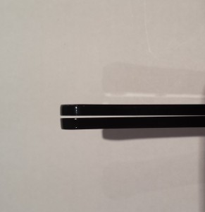
| Lasercutting produces a kerf on the edge of the rods. This produces holes with differing diameters on each side of the part. The rods should be paired and arranged such that the kerf is mirrored, as shown. |
 |
| Take one pair of rods. Push two screws through one of the rods and secure with M3 nuts. |
 |
| Fit the second rod and loosely attach two Nyloc nuts. |
 |
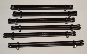
| Repeat the above steps until all six rod pairs are assembled. |
 |
Mounting the head
You will need the following parts:
| # |
Component |
Qty |
Type |
|
Rod pairs |
6 |
Assembled |
|
Head |
1 |
Assembled |
|
Fisher |
1 |
Part-assembled |
|
|
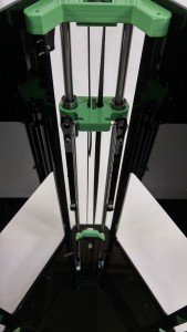
| Attach the rod pairs to the steel balls on the carriages.If the threaded balls are secured with a thread locking compound, now is a good time to apply lubricant to the bearing surface. Lithium grease, as used for bicycle maintenance has been proven to work well. If the balls are not yet threadlocked, the grease should be applied following the commissioning stage (which contains a reminder). |
 |
| Hang the head on the dangling ends of the rod pairs. The head should be orientated such that the cooling fan is nearest the side panel (not containing a logo). |
 |


