DRAFT – these instructions are not final, and are likely to change.
Fitting the Duet
You will need the following parts:
| # |
Component |
Qty |
Type |
|
Fisher |
1 |
Part-assembled |
| 394 |
Duet electronics |
1 |
Electronics |
| 1186 |
M3x16mm button head screw |
4 |
Fastener |
| 212 |
M3 washer |
4 |
Fastener |
| 258 |
M3 nut |
8 |
Fastener |
| 193 |
Power jack |
1 |
Electronics |
| 455 |
Power jack nut |
1 |
Electronics |
|
|
| Screw the four button head screws fully down into the base plate. |
 |
| Fit a washer and nut to each of the four button head screws. |
 |
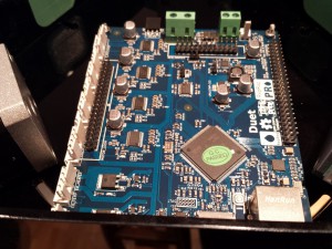
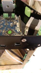
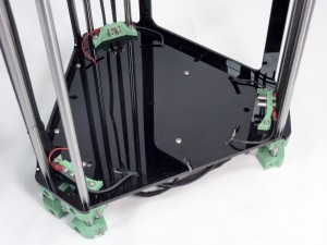
| Mount the Duet electronics, and secure with four M3 nuts. |
 |
| The DC power jack may now be fitted as shown. |
 |
Bed probe wiring
You will need the following parts:
| # |
Component |
Qty |
Type |
|
Fisher |
1 |
Part-assembled |
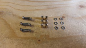
| 1253 |
Round spacer |
6 |
Hardware |
| 257 |
M3x12mm cap head screw |
6 |
Fastener |
| 212 |
M3 washer |
6 |
Fastener |
| 1202 |
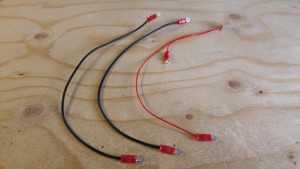
Bed probe wire |
2 |
Wiring |
| 1203 |
Bed probe loom |
1 |
Wiring |
|
 |
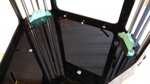
| Fit the bed probe loom 3-way connector to the E-stop header on the Duet. Push the wires through the slots in the base, as shown. |
 |
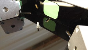
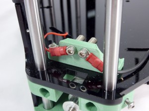
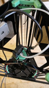
| Attach the ring terminals of the bed probe loom and bed probe wires to the bed mounting brackets. For each connection, the order is M3x12mm cap head screw, ring terminal of loom, bed mounting bracket, M3 washer, round spacer. (Belt has been removed to show connection in this picture.) |
 |
| View from the front of the bed mounting bracket. |
 |
| Repeat the above steps for all six connections. The circuit goes around the circle. The balls on the print surface will complete the circuit (see later). When the nozzle pushes down on the bed, the circuit is broken. This calibrates the nozzle height. |
 |
Hot end loom
You will need the following parts:
| # |
Component |
Qty |
Type |
|
Fisher |
1 |
Part-assembled |
| 585 |
Hot end loom |
1 |
Wiring |
| 112 |
M3x25mm cap head screw |
1 |
Fastener |
| 212 |
M3 washer |
1 |
Fastener |
| 204 |
M3 Nyloc nut |
1 |
Fastener |
| 1264 |
P Clip |
1 |
Hardware |
|
 |
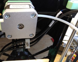
| Route the hot end loom through the rectangular slot in the base plate, up below the extruder drive motor, and loosely looped over and down towards the hot end. |
 |
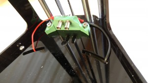
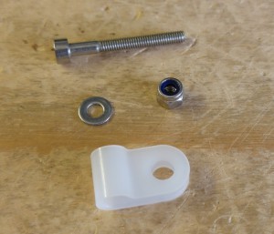
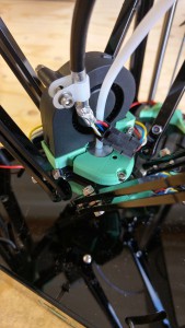
| Push the P Clip onto the hot end loom, near the end of the sheath, then attach to the cooling fan using the cap head screw. The loom can now be connected to the hot end wiring. Take care to route the wires around the front of the bowden tube. |
 |
Endstop looms
You will need the following parts:
| # |
Component |
Qty |
Type |
|
Fisher |
1 |
Part-assembled |
| 552.1 |
Endstop loom (600mm) |
1 |
Wiring |
| 1198 |
Endstop loom (500mm) |
1 |
Wiring |
| 1199 |
Endstop loom (800mm) |
1 |
Wiring |
| 1264 |
P Clip |
2 |
Hardware |
| 112 |
M3x25mm cap head screw |
1 |
Fastener |
| 212 |
M3 washer |
1 |
Fastener |
| 204 |
M3 Nyloc nut |
1 |
Wiring |
| 1249 |
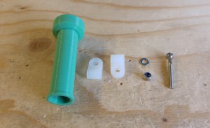
Spool spigot |
1 |
Printed |
|
 |
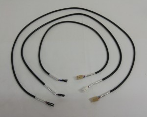
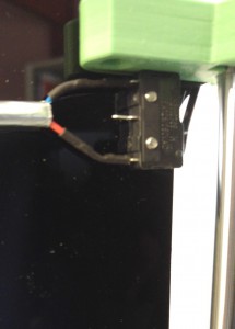
| Push the endstop looms onto the outer legs of the microswitches. There are three lengths of loom. Looking down onto the machine, the shortest loom (X axis) should be fitted to the endstop to the left of the extruder drive, the next longest to the right of the extruder drive (Z axis), and finally the longest loom fits onto the microswitch on the front panel (Y axis). |
 |
| The two longest endstop looms are secured to the side panel with a P Clip on each, and utilising the screw which secures the spool spigot in place. |
 |
Extruder drive motor loom
You will need the following parts:
| # |
Component |
Qty |
Type |
|
Fisher |
1 |
Part-assembled |
| 1042 |
Motor loom – 500mm |
1 |
Wiring |
|
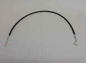 |
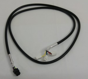
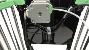
| Push the six way connector into the motor socket as shown. The three endstop looms and extruder drive motor loom can now be secured to the side panel using a cable tie through the slots. |
 |
Duet connections
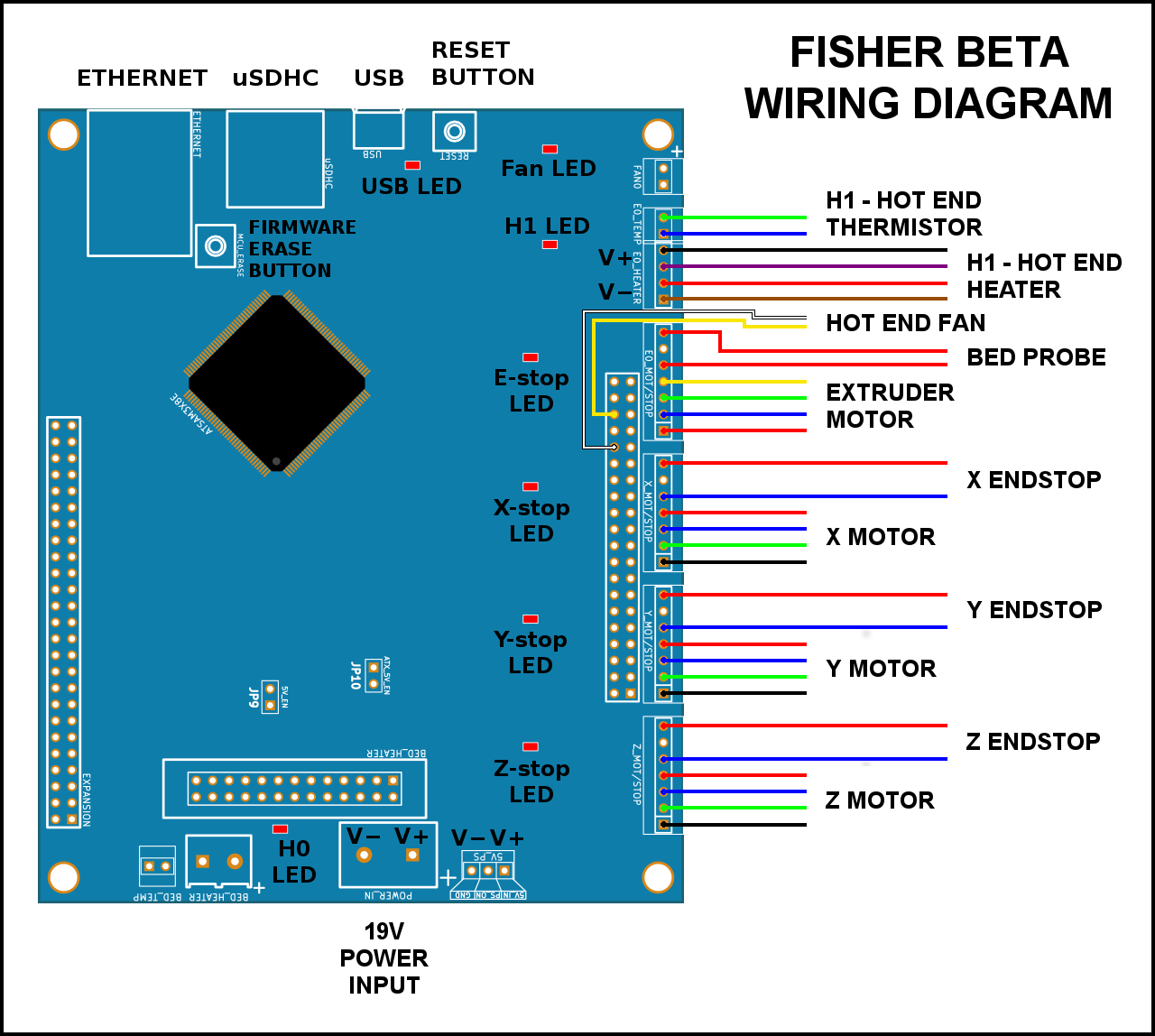
Wiring diagram
The instructions below show the fitting of the wiring. If in doubt, refer to this wiring diagram.
Duet wiring connections
You will need the following parts:
| # |
Component |
Qty |
Type |
|
Fisher |
1 |
Part-assembled |
| 477 |
Motor loom – 160mm |
1 |
Wiring |
| 478 |
Motor loom – 90mm |
2 |
Wiring |
| 1201 |
DC cable – 250mm |
1 |
Wiring |
|
|
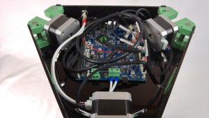
| Connect the wiring looms to the Duet, as shown in the picture from left to right (click on the picture for a larger version). Also refer to wiring diagram, above. |
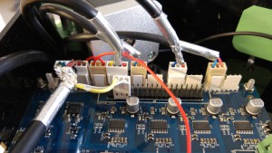 |
| FAN0 – NO CONNECTION! Do not connect anything to the first two pins on the left. They are not used on the Fisher. |
|
| E0_TEMP – Hot end thermistor (green/blue, 2-way) |
|
| E0_HEATER – Hot end heater (black/purple/red/brown, 4-way) |
|
– Hot end fan (yellow/none/white, 3-way)
NOTE: this connects to the double row of pins, NOT to ‘FAN0’. From the left, there should be two clear pins, then the yellow wire, another pin (covered by the housing, but not connected), then the white wire. |
|
| E0_MOT/STOP – (on first three pins) Bed probe (red/blank/red, 3-way) |
|
| E0_MOT/STOP – (on the other four pins) Extruder drive motor (yellow/green/blue/red, 4-way) |
|
| X_MOT/STOP – X endstop (blue, space, red, 3-way) |
|
| Y_MOT/STOP – Y endstop (blue, space, red, 3-way) |
|
| Z_MOT/STOP – Z endstop (blue, space, red, 3-way) |
|
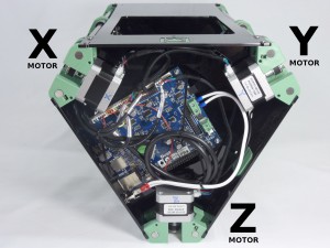
X_MOT/STOP – (on the other four pins) X motor (red/blue/green/black, 4-way)
Now connect the X motor to the Duet, using a 90mm motor loom. This is the motor closest to the motor connection pins on the Duet. Check that the endstop at the top of this tower is the one connected next to the X motor. |
 |
Y_MOT/STOP – (on the other four pins) Y motor (red/blue/green/black, 4-way)
Next the Y motor, using a 90mm motor loom. This is the motor nearest the large screw terminals on the end of the Duet board. Check that the endstop at the top of this tower is the one connected next to the Y motor. |
|
Y_MOT/STOP – (on the other four pins) Y motor (red/blue/green/black, 4-way)
Now the Z motor, using the 160mm motor loom. This is the motor nearest the ethernet socket on the Duet. Check that the endstop at the top of this tower is the one connected next to the Z motor. |
|
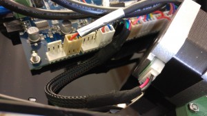
| This picture shows the motor connections, and orientation. To make the motor wiring easier, you can turn the motor around. Slacken off the belt tensioner, unscrew the four motor screws, and turn the motor around. Mind out for the bed spring, which rests on top of the motor. Fit this back in place, and retighten the screws, then the belt tensioner. |
 |
| Finally, connect the DC power cable. One of the cores has a black stripe running along it’s length. Connect this to the negative terminal (on the left hand side as viewed in the photograph). |
 |
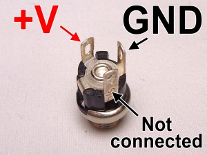
| Connect the DC power cable to the tabs on the back of the jack. Ground is the centre of the three tabs (the wire with the black stripe should connect to this), and positive is the tab that connects to the centre pin. |
 |
Jumper
You will need the following parts:
| # |
Component |
Qty |
Type |
|
Fisher |
1 |
Part-assembled |
| 285 |
PCB Jumper |
1 |
Electronics |
|
|
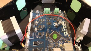
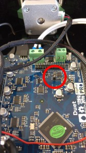
| Fit the jumper onto the 5V_EN (JP9) header pins (location highlighted in the picture). This uses the on-board 5V regulator to supply power to the main processor of the Duet, when 19V power is connected. |
 |


