Contents
Thermistor assembly
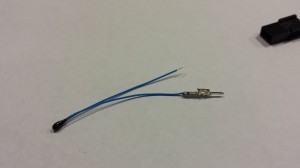
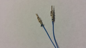
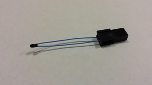
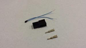
The first step requires assembly of the heated bed thermistor. The following are required:
|
 |
Heated bed assembly
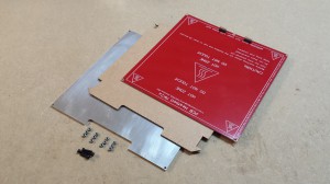
The heated bed assembly requires the following parts:
| Cover the soldered connections with a piece of Kapton tape. This will save you inadvertently shorting out the connections. | 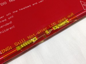 |
| The thermistor bead fits into the central hole in the heated bed PCB. Secure it in place with some Kapton tape. | 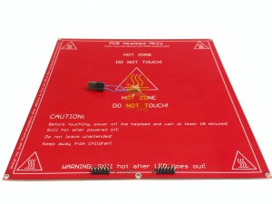 |
| Make sure the thermistor protrudes through the hole in the PCB a little. It will then have good contact with the aluminium heat spreader, and temperature readings will be more accurate. | 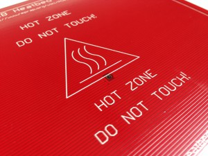 |
| Make a dent in the cardboard where the thermistor is, so the cardboard sits flat on the PCB. | 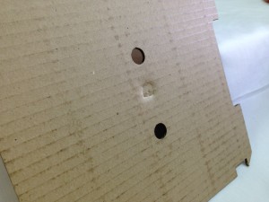 |
| The contacts and pins of the heated bed PCB are not symmetrical. Depending on how old your kit is, the cardboard may or may not be asymmetric too. Make sure you install it to give space around the pins, or it is more difficult to fit the heated bed connectors. | 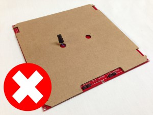 |
| This picture shows the cardboard the correct way around. Make sure the thermistor connector protrudes through the hole in the cardboard. Use Kapton tape around the edges to hold the cardboard onto the heated bed. | 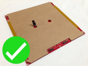 |
| CAUTION! The pin connectors on the heated bed are off-centre, as is the notch in the Aluminium heat spreader. When assembling the heated bed, make sure that the Aluminium heat spreader is the correct way around. It MUST NOT be assembled so that is can touch the electrical contacts of the heated bed, or the heat spreader will be +12V. This can then be passed to the hot end or IR sensor if they touch one of the metal clips, potentially destroying the Duet electronics. |
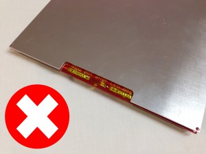 |
| This picture shows the aluminium heat spreader correctly installed. The Kapton tape will also help insulate from potential short circuits. Newer aluminium heat spreaders are cut symmetrically, so the aluminium cannot touch the PCB contacts. | 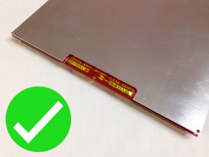 |
| Assemble the heated bed as shown, using the five cap head screws to fix the Aluminium heat spreader plate to the heatbed PCB. Use two M3 nuts on each screw. This gives enough spacing for the cardboard insulator to fit beneath this assembly when it is fitted to the Y axis of the machine. | 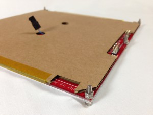 |
| The completed heated bed assembly. | 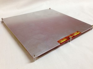 |
Alternative build – for ‘Swiss’ clips and/or adjustable bed
We supply two different types of bed clip. Ormerods shipped before 1st May 2014 have foldback clips, while after this date you may have been supplied with ‘Swiss’ clips, which are picture frame clips. This necessitates a change to the heated bed build. If you have foldback clips, you can also make the following change. It can make the bed more stable, and allows easy manual adjustment of the bed to make it flat. This is also covered in the ‘Axis Compensation’ instructions.
You will need a couple of extra screws and nuts. These may not have been supplied with your kit! Contact RepRapPro support if you need them.
|
Picture to come |
| These are the foldback clips that are supplied with all Ormerod kits shipped before 1st May 2014. If you have these, you do not need to follow this section of the instructions, but you can if you want to have a manually adjustable bed. | 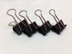 |
| These are the ‘Swiss’ clips, commonly used on picture frames, that are now supplied with kits. They are much lower profile, and reduce the chances, and the effects, of the nozzle hitting the clip. Because they are a bit bigger underneath, the heated bed needs to be higher off the MDF bed. | 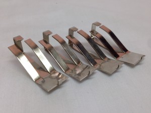 |
| For the most part, follow the instructions in the section above. However, replace the screw between the heated bed PCB contacts with an M3x20mm cap head screw. Put a washer, then an M3 nut on the other side, done up tight. Then put the M3 nyloc nut on the screw. The heated bed will rest on this, and the height of the bed can be adjusted. | 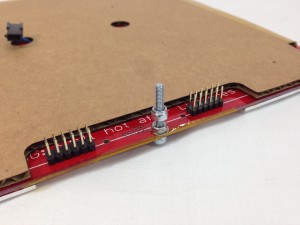 |
| On the two corners at the back of the heated bed, again replace the screws with M3x20mm cap head screws. Put a washer, then an M3 nut on the other side, done up tight, on each. Then put the M3 nyloc nut on each screw. | 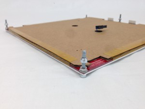 |
Print surface
|
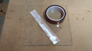 |
| To accurately set the Z axis height above the bed, we use a non-contact infra red probe. This is mounted on the x-carriage, which means we can also measure the height across the bed, and compensate if is not level. Paper pieces are used as reflective targets for the infra red probe around the bed. Cut the plain white paper (or foil) into four 25mm x 25mm squares. It doesn’t need to be exactly this size; whatever is convenient. Using white sticky labels makes it easier to stick them on the glass before covering them with Kapton. | 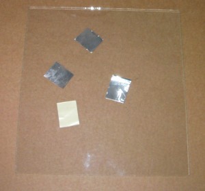 |
| Stick the paper (or foil) squares to the four corners of the glass plate and cover the glass plate (foil side up) with Kapton tape. With paper squares, they will need to be 5mm in from the edge, so they can stick. Adhesive-backed foil or labels can be closer to the edge. When applying the Kapton tape, take care to exclude bubbles. Don’t pull the tape too taught before you lay it down. Gaps between the strips are preferable to overlaps. Another way to apply the Kapton tape is to slide it on with soapy water, move it into position, then squeegee out the water. You have to wait for it to dry out before use. | 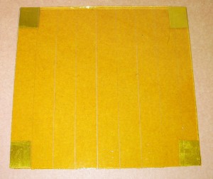 |
| We use the Kapton as the print surface, so when you install it onto the bed, it should be installed Kapton-side-up. This means that the squares are also on the top surface, so we can use the close accuracy of the proximity sensor for homing. The side without Kapton on it is just plain glass, and sits against the Aluminium heat spreader. | 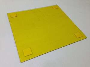 |

