
For an introduction, all the documentation on this project, and to read what we did up to this point see our Github repository here.
After a year-and-a-half gap (caused, inter alia, by the Covid pandemic) we have come back to the Electric 3D Printer. We’ve set it up to “print” random shapes in a way we shall immediately describe. But what use are random shapes? They can be used to train a neural network to generate shapes that are not random automatically. We shall outline our proposal for that at the end of this section.
We have written a Python wrapper for the C++ P.D.E. solver that works out the printed shapes. It’s in the Software/GAN directory of the repository linked above.
What it does is to generate a list of pairs of electrodes on the cylindrical boundary of the reaction vessel of the Electric 3D Printer and then assign random voltages to each pair. These are then fed into the solver, and the output of that is read back into the Python program to be subjected to the marching cubes algorithm to see what the pattern prints. The system now uses the standard Python version of marching cubes, import mcubes, to generate the shapes from the charge integrals, which works a lot better, incidentally.
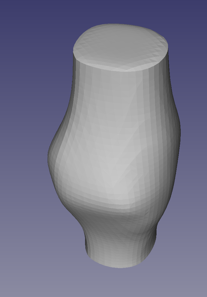
Here is an example of the sort of thing that results; a lumpy cylinder:
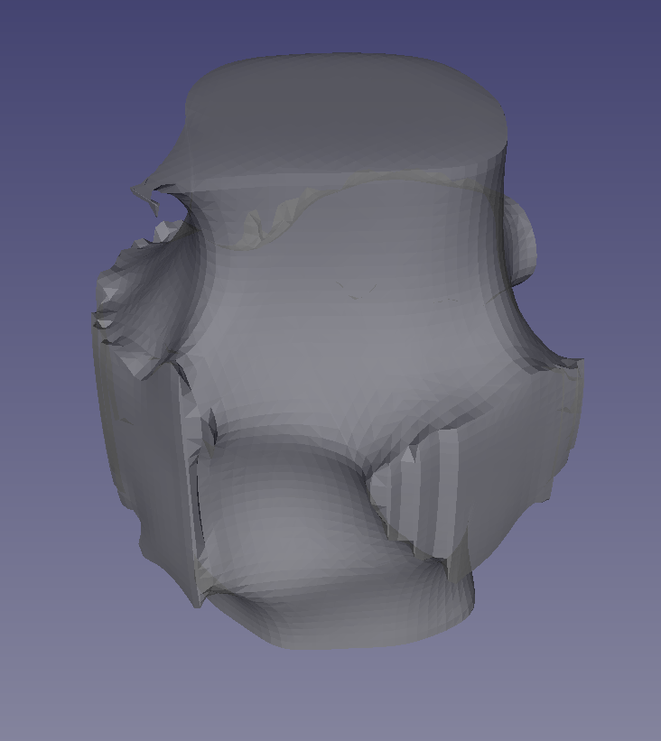
For this the pairs of electrodes were distributed at random. To get an idea of what’s going on here’s another run with fewer random electrode pairs:
And here is the same shape with a set of straight lines superimposed on it that join the pairs of electrodes that created it:
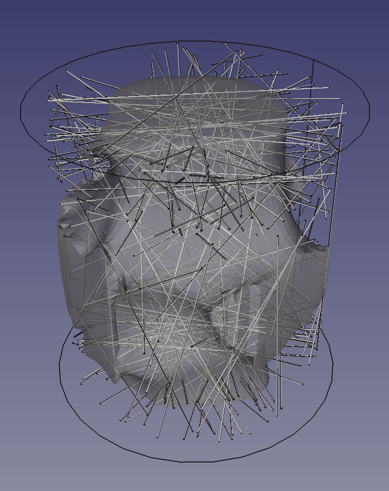
Because fewer electrodes were used, and consequently less current was passed through the volume, more of the shape has remained solid, in some cases right out to the boundary.
But why do we get a cylinder-like shape extending the length of the reaction chamber? In part, this is because that’s the shape of the chamber, and what we’re doing is to erode away inside it. But also, consider a slice across the cylinder to make a disc:
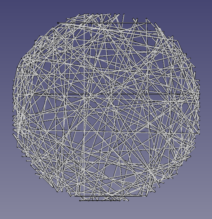
If we choose 100 pairs of random points from the uniform distribution over the disc’s circumference then draw the chords between them, this is what we get. As you can see, the density round the edges is higher than in the middle for the intuitively obvious reason: a random pair of points are not all that likely to be more or less diametrically opposite each other. This is what’s going on in three dimensions as well, and is another reason that we tend to make roughly cylindrical shapes in the middle. Of course the current doesn’t just flow along those narrow lines; it would balloon out between the electrode pairs, eroding more material.
But we don’t just want to make cylinders and prisms. The physics of the process is introducing a bias into it and, if we can quantify that bias, we can apply its inverse in an attempt to correct it. In fact I have started to do that in the two solids at the start of this section. The electrode pairs were not chosen from the uniform distribution over the surface of the cylindrical reaction chamber. They were biased towards the top or bottom – this is the reason that the solids have bulges around half way up the cylinder – and biased to be more likely to be near to diameters than random chords would be.
It is easy to generate pseudo-random numbers from any distribution you like. You just integrate the distribution function to get the corresponding cumulative distribution function (CDF), then invert this to get random points from the desired distribution. That is to say you feed uniformly distributed random numbers into the y axis of the CDF and the resulting x values will be from the desired distribution. We shall shortly add a couple of functions to the Python program that generates the voltage patterns to allow any distribution to be specified by points along it. Simpson’s Rule will then be used to make the CDF, and the inverse of that will give the randomness required. The aim will be to print random blobs in the middle, not cylinders.
When all this is working we will have a means to train an ordinary neural network to generate the pattern of voltages needed to print a given input shape. But it should also be possible to use that to make a Generative Adversarial Neural-Network to create all sorts of useful engineering shapes automatically.
How will the first stage work? We can generate random input patterns (the pairs of charged electrodes), and we know the shape of the result (the output of the C++ program that solves the P.D.E.). What we want for a given output shape (an STL file, say) is to know the pattern of electrode voltages that will create it. So we can make a training data set as big as we like, albeit random, and hope that a network trained on it will be able to make regular shapes as well.
The next stage is to get the voltage distributions right to make blobs, not cylinders, then we will move on to the neural network training.
Finally, see this interesting tweet.
Connect with us
Keep up to date on the latest RepRap Ltd news:
Dear Sir,
It’s great that you are continuing to work on this solution!
Finally, I have published comprehensive information on the principle of operation of Self-Created Metal Composites. These are very similar areas … I will be very grateful for any comments. Thank you!
https://www.linkedin.com/pulse/rubicon-micha%25C5%2582-baran
That’s very interesting. Did the flat surfaces occur naturally, or did you have to abrade the parts to get them?