
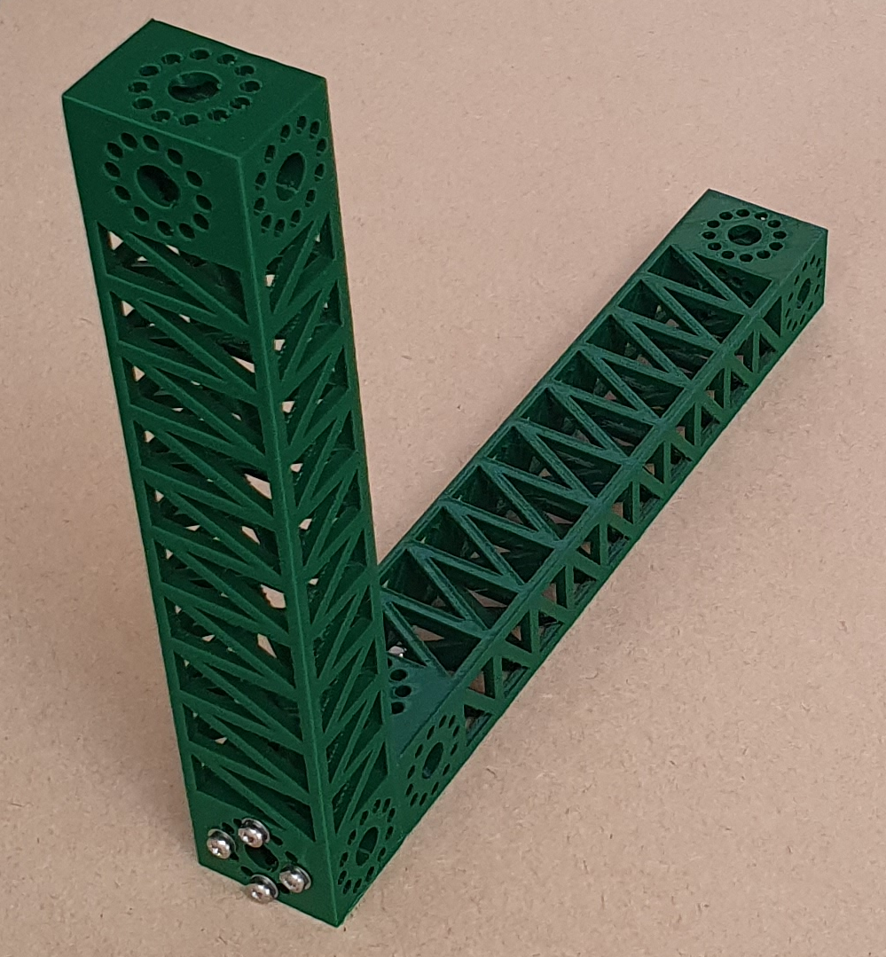
A while ago Naomi Wu 机械妖姬 very kindly sent us one of Creality‘s infinite-Z belt printers. Lots of people have printed long I beams on this type of machine, but we thought that we’d write a Python FreeCAD program to generate parametric beams more suitable for 3D printing, taking advantage of the fact that complexity is more or less free with this technology and that infinite-Z belt printers can print many overhanging shapes without support material. The result is a beam that is about as stiff as a steel beam of the same weight.
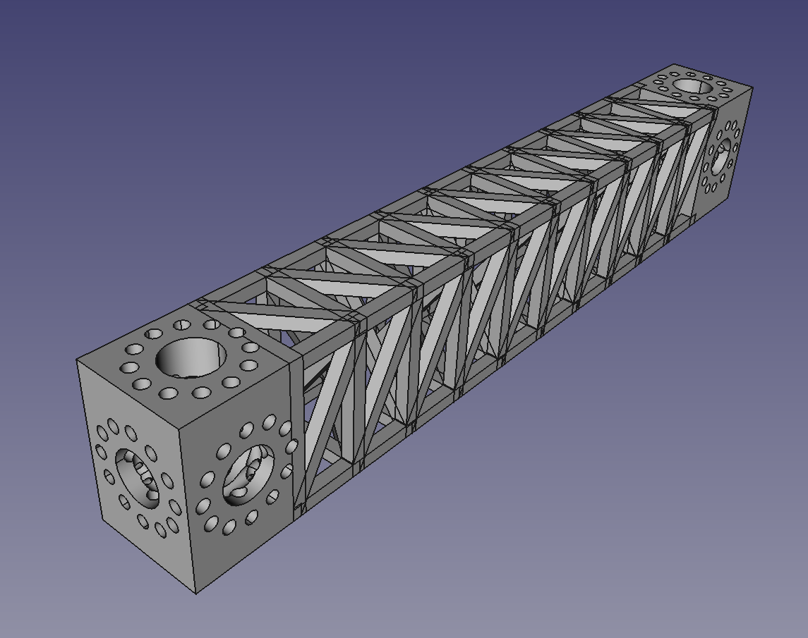
The image above shows an example of the Python output. All you need to specify is the length, width, and height, the thickness of the struts, and the diameter and number of the screw holes in the mounting blocks at the ends. The program then automatically generates the entire beam.
The central section consists of a row of open boxes, each of which is decomposed into tetrahedra. This effectively means that the entire shape is built from tetrahedra – the strongest shape – and also that most of the material is on the outer faces which gives a high second-moment of cross-sectional area for bending resistance in all directions. The diagonals are angled so that a belt printer with a 45o Z movement can print the entire structure without support material.
The blocks at the ends are for bolting the beams to each other or to other items. The rings of 12 small holes shown allow any orientation in increments of 30o. The large holes are to allow wiring, tubes and other services to be run down the middle of the beams and connect up at the ends, or to allow things such as drive shafts to be accommodated.
It turns out that FreeCAD can’t model the rings of small holes. If you want to skip a technical explanation of why this is so then just know that there’s a work-round and ignore the red section that follows.
The image below shows the shape of all the small holes that needs to be subtracted from the end blocks.
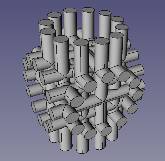
As you can see, there are a lot of common tangencies where cylinders cross. When FreeCAD throws the calculation of these to Open Cascade, which is the geometric modeller that FreeCAD uses to represent shapes, it goes away and gets lost in its own thoughts (CPU: 100%…) and you never hear from it again. I (Adrian) don’t think this is really a bug in Open Cascade; any boundary-representation (B-rep) geometric modeller would probably have the same problem. Because (as the name implies) B-rep modellers represent shapes by recording the topology and geometry of their surfaces, they have to put a lot of effort into doing things like working out the curves of intersection between surfaces, and keeping all the shape topology consistent while this is done. In some cases this is quite literally impossible. For example there is no closed-form solution to working out the curve of intersection between two NURBS surfaces; that always has to be approximated. Even for cylinder-cylinder intersections, things can get complicated (look at the topological stitch-lines running along the cylinders in the picture; these all have to be matched up).
Set-theoretic (or CSG) geometric modellers have none of these problems because they don’t represent the surfaces of objects; they represent their solidity. In their simplest form they can only answer one question: given a point (x, y, z), is it inside the solid part of the object or outside? – a so-called membership test. (In practice set-theoretic modellers can all do much more than this.) And they do membership-tests with rock-solid certainty. Unfortunately they are rarely used in CAD systems, except as a means of input. The reasons for this are historical rather than technical. For example the invention of the hardware depth-buffer, which allows computer graphics systems to make pictures of large numbers of triangles blindingly fast, favoured the early development of systems that represent surfaces (which are easy to triangulate). If instead a hardware ray-tracer had been implemented, then set-theoretic modellers (which are natural choices for ray tracing) might have come to dominate. (I wrote a set-theoretic modeller called SvLis in C++ about three decades ago; if you want to go mad see if you can get it going with a modern C++ compiler. If you succeed, DM me…)
The work-round in FreeCAD that allows the cylinders to be dealt with is as simple as it is nasty. The cylinder radii are perturbed a tiny bit at random:
cyl = Part.makeCylinder(d/2 + random.uniform(-0.01, 0.01), z + 0.2)
This means that what were common tangencies no longer are, quite . The perturbation is well below the resolution of 3D printing.
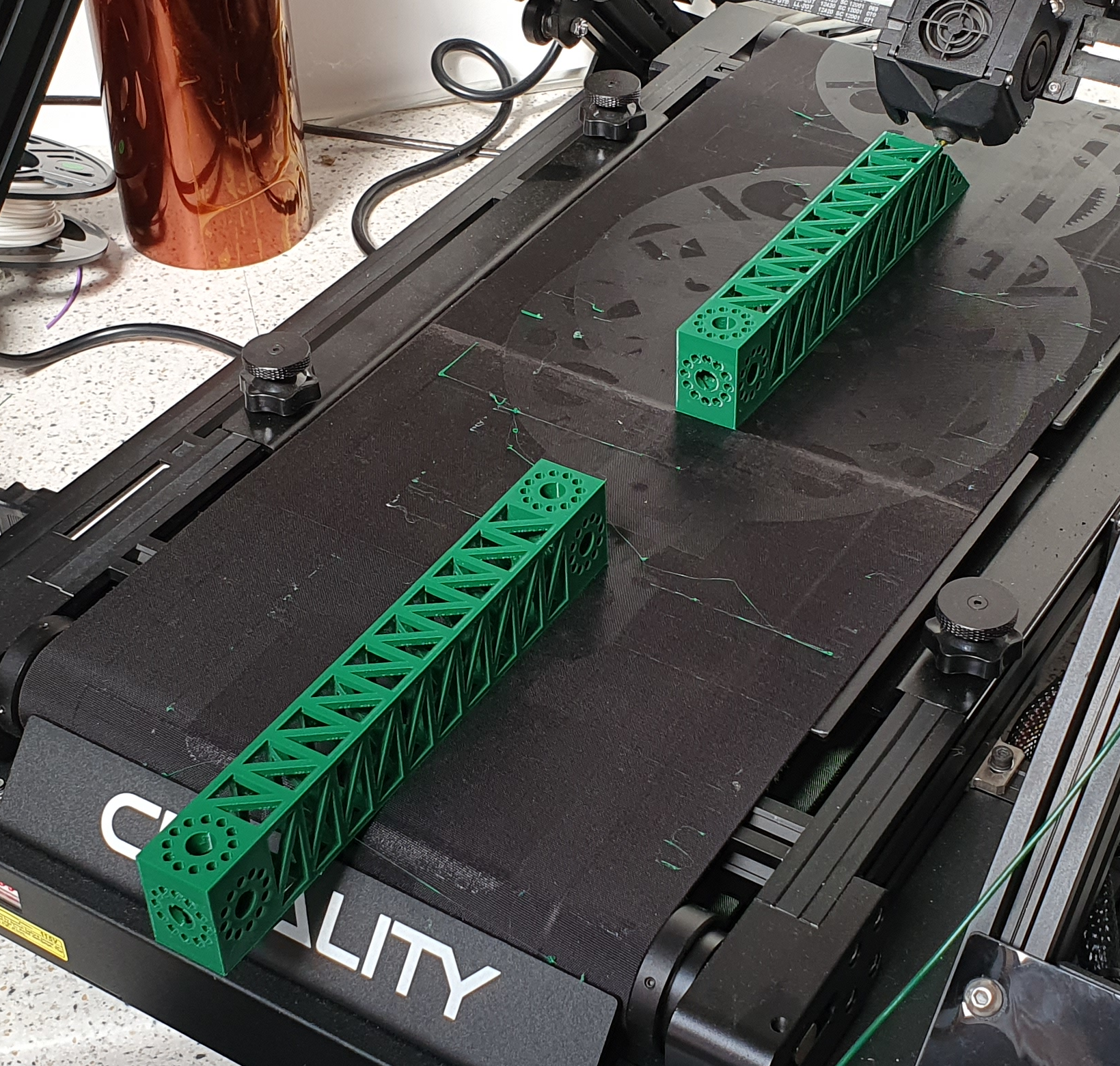
The following image shows the beams being printed in PLA.
When it was done, we subjected one to a bending test using weights and a dial gauge to measure deflection.
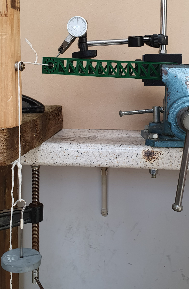
Note the pieces of wood on the left; if only we had some way to 3D-print structural parts…
The beam was held and deflected sideways so it couldn’t slip in the vice. Here are the results:
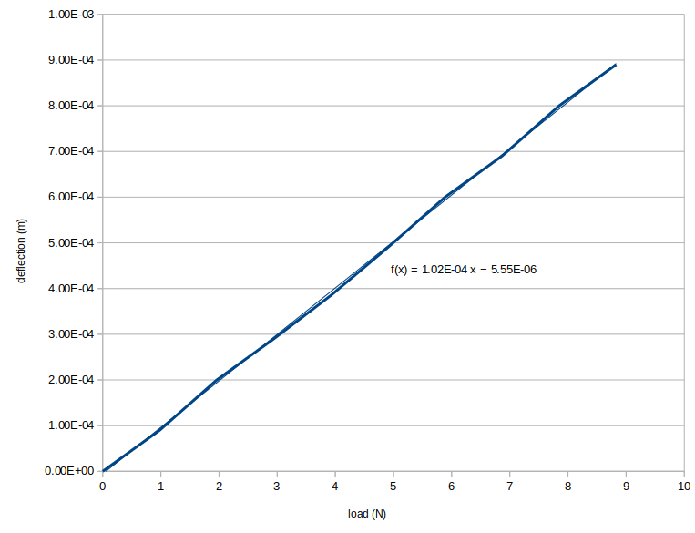
The equation is that of the least-squares fit straight line. The effective length of the beam (ignoring the clamped end) was 175 mm. Its stiffness was 1.02 x 10⁻⁴ mN-1 from the graph. This meant that its flexural rigidity (EI) was 17.5 Nm2 (where E is Young’s modulus in Pa and I is the second moment of area in m4). Thus we can work out that an equivalent steel beam would be 5 mm square. (That is to say, a steel beam with the same EI value.)
The printed beam weighed 47.7 grams. Coincidentally a 5 mm square steel beam of the same length (including the clamped end) would weigh about the same (47 grams), so we have made a printed beam that is about as stiff as the same weight of steel.
The printed beam was physically bigger than its steel equivalent, of course. This is to be expected as PLA has a much lower elastic modulus than steel. But printing allows any size easily to be created, it allows services to be run up the insides, and it allows a fancy pattern of attachments and screw holes to be created at the ends, all automatically.
It would also allow a beam of beams to be printed. Because it needs no support, this beam design could be used as the struts of a much bigger beam in the same pattern. This would make a fractal beam…
The Python program and all the other files for this project are in our Github repository here.
It has not escaped our attention that beams of this sort would be ideal components for building a RepRap infinite-Z belt printer.
Connect with us
Keep up to date on the latest RepRap Ltd news:
Pingback:3D Prints Of Steel — Um — PLA, Rather – Hackaday – 3Dxpert
How are these being connected? I can’t tell from the photo. Are they really long bolts? Threaded inserts? Some kind of rivet?
Seems it’d be most convenient to connect touching sides (short bolt or rivet) instead of outside sides (looks like 75mm+ and hard to find), but the ends with the connector holes don’t look large enough to get nuts or bolts into easily.
Any ideas?
55mm M3 screws, which seem to be a standard size (there’s a page of them on Amazon, for example). Of course the screw size needed depends on the beam cross section with the current design. In needs screws a nut depth longer than the smallest beam dimension. But it would be pretty straightforward to modify the code to generate forms that use different attachment mechanisms.
can i get the model for my use plz
There’s a link in the post.
It’s https://github.com/RepRapLtd/Infinite-Z-Beam