
We have been experimenting with 3D printed Ravigneaux epicyclic gears to get a high-reduction-ratio gearbox in a compact space for making robots. They work if you drive them with a high-torque from an already geared-down motor, but they suffer from high friction, which makes them unsuitable for being driven by small motors directly.
Here, in contrast, is the 3D printed cycloidal gearbox from James Bruton’s Open Dog robot Version 3.
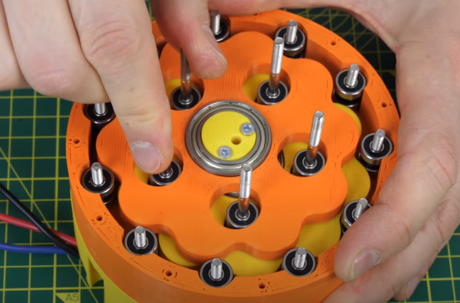
Cycloidal gearboxes are great because they are low friction, compact, and give high reduction ratios. They are also easy to print, and – given that ball bearing races are low cost – inexpensive to make. Fitted to the output of a brushless DC (BLDC) electric motor they are ideal for robot drives.
Here is a picture of their structure, taken from the useful TEC Science page on them here.
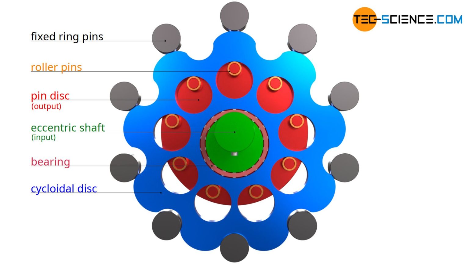
The green shaft in the middle is driven, causing the eccentrically mounted blue cycloidal disc to roll round the stationary outer fixed ring pins. As it does so circular holes in it push against the pins of the red pin disc, causing the red disc to rotate. This is the output, which is coaxial with the input. Sometimes the pins in these drives are actual pins. However, if instead ball bearing races are used for them you get very low friction and high efficiency.
We have written an open-source Python program in FreeCAD to generate the components of these drives automatically from a few parameters, such as the diameters of the bearings you want to use and the overall diameter of the gearbox that you want. The TEC Science page gives almost all the algebra you need to generate the basic cycloid curve and we used that, but the cycloid also needs to be offset to generate the required contracted cycloidal disc. We have added a function to do that in the program. Here is a result:
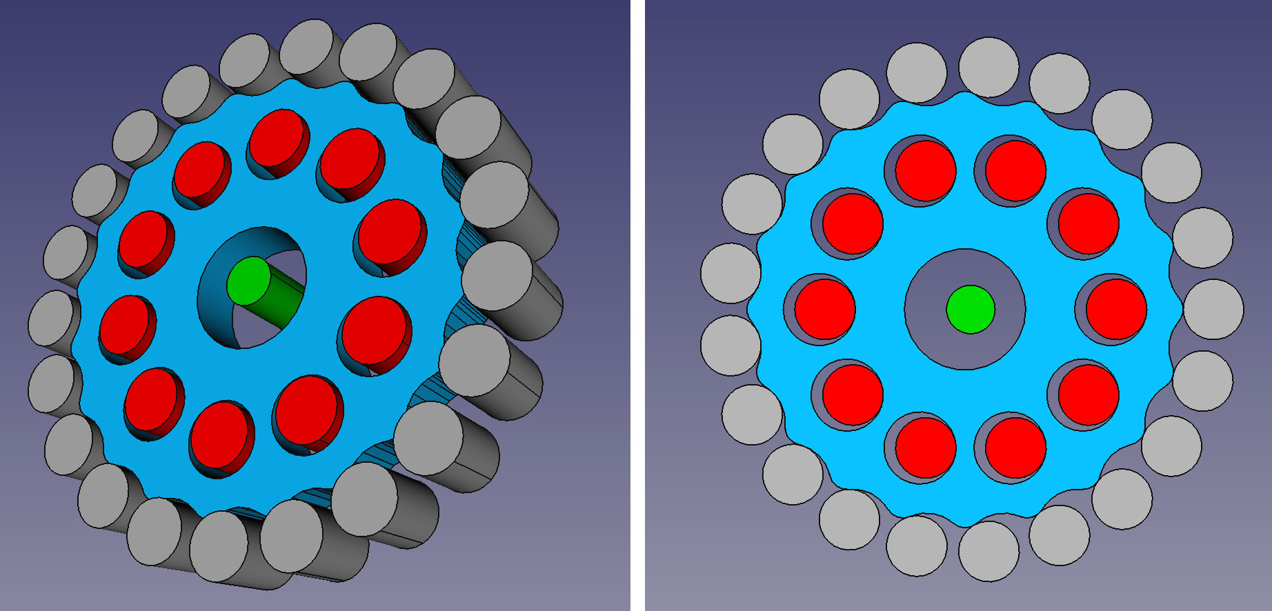
In this example, the grey outer cylinders are 5mm diameter ball bearings that mount on 2mm shafts (which is to say they could be retained by M2 screws), as are the red inner bearings. The overall gearbox is 45mm in diameter. The green cylinder shows the axis of the drive. As you can see the blue contracted cycloid disc is eccentric to that. The reduction ratio is 20:1.
By changing the parameters you can generate pretty much any size of contracted cycloidal gearbox you want with any reduction ratio. You can also stack them to multiply reduction ratios.
We have also added an option to create a lip above and below the cylindrical and the contracted cycloidal surfaces where the bearings run. This helps to locate all the components in the axial direction. Here is the result for a lower reduction ratio gear (8:1) with fewer bearings so you can see what is going on:
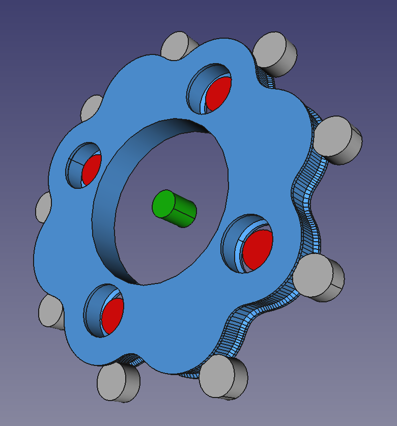
This stops axial movement of the cycloid, which is now constrained by the bearings. This makes gearbox design a lot easier.
We have used this to design a complete 8:1 gearbox:
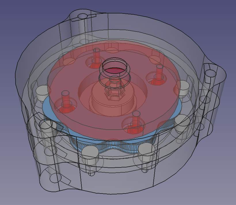
This is stackable, so two would make 64:1. Plus, of course, the Python program makes it easy to create different ratios that will fit in the same size, so virtually any gear ratio is achievable. If you look at Bruton’s design above you’ll see that he has a more compact stacking arrangement in which a cycloid directly drives the one stacked above it. We will investigate this ourselves.
Here are the top and bottom halves of the gearbox assembled:
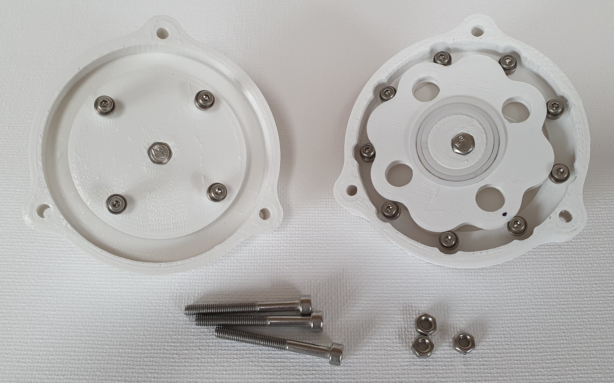
And here is a video of it working:
The FreeCAD Python macro that generates these gearbox components is in our Github repository here in the file contracted-cycloid.py and the complete gearbox design is in Mechanics/gearbox.FCStd.
Connect with us
Keep up to date on the latest RepRap Ltd news: