
How can we correct for every single inaccuracy, non-linearity, bend in an axis slider, error in steps-per-millimeter and all the rest in a RepRap machine using just one technique? Read on…
 |
 |
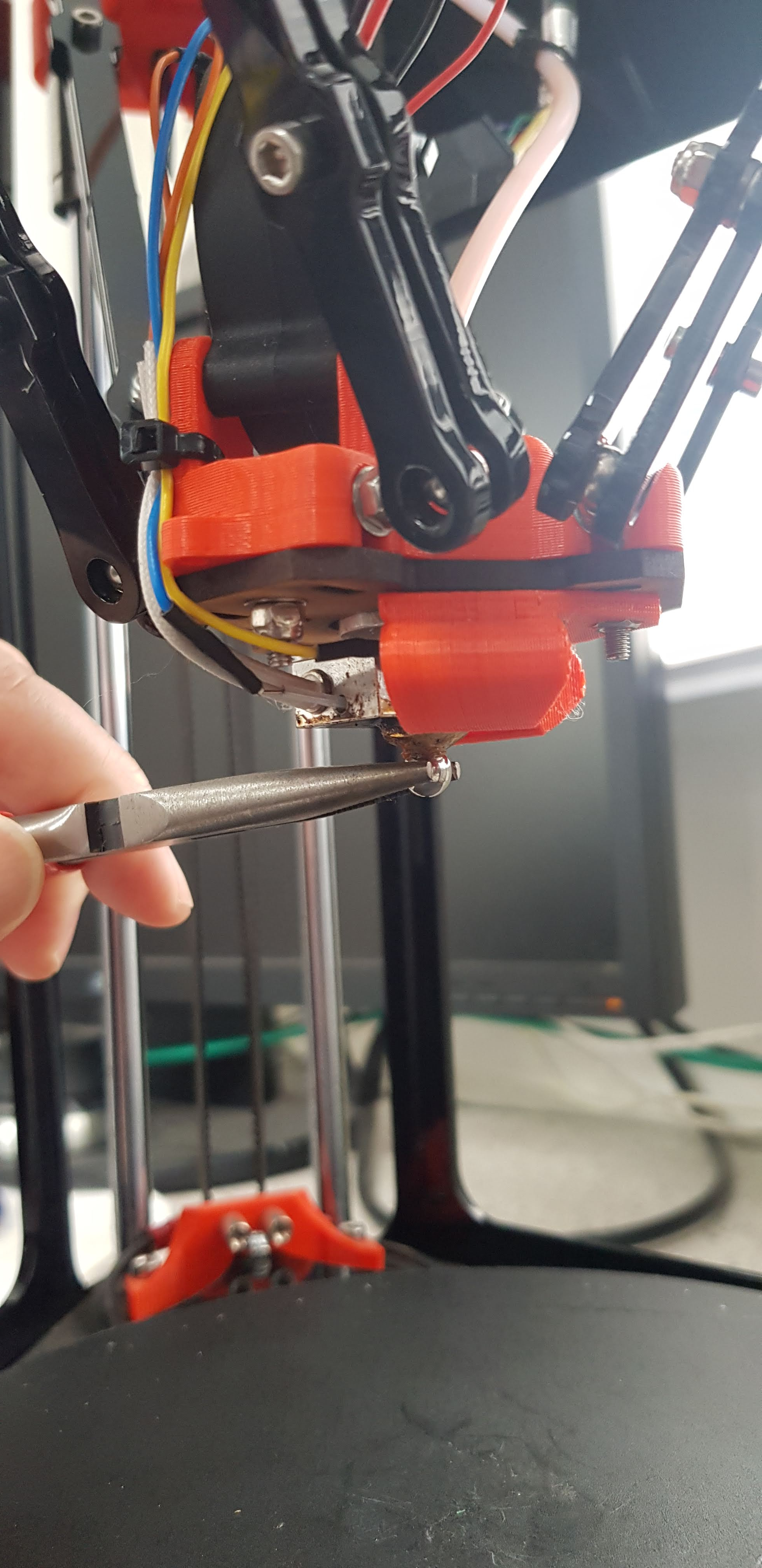
Here’s me, deliberately blocking the nozzle of my RepRap Fisher. I held an M3-tapped ball-bearing against the nozzle with a pair of long-nosed pliers, extruded a bit of filament into the thread hole, and let it all cool.
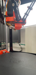
RepRap Fisher uses its nozzle to probe the bed. The bed is on three sprung-contacts wired in series, so any slight down-push (literally a few microns) of the bed anywhere on its surface breaks one of the contacts and acts as a probe-triggered signal. Here’s the Fisher probing the bed with the ball:
The centre of the ball is directly under the centre of the nozzle, and we know the radius of the hole that’s held against the nozzle’s cone and the radius of the ball, so we know exactly where the centre of the ball is relative to the nozzle tip. Whenever the ball touches anything its centre point is always the ball-radius away from the thing it has touched.
OK – so we can probe the bed with the ball. But we could probe the bed with the nozzle before, so what’s new?
Well. Now we can probe sideways, as well as vertically. I stuck an aluminium block to the bed with double-sided tape and probed it in the X direction:
As the ball touches the block sideways the tiny movement (again microns) translated to the bed contacts causes a contact to break as before. And we know the centre of the ball is exactly the ball’s radius away from the surface of the aluminium block.
Great! We have made our RepRap into a coordinate measuring machine that works in all three dimensions. The coordinate measuring machine could be made from any 3D printer that either has bed contacts for probing (like RepRap Fisher), or an active nozzle probe that will trigger both vertically and sideways (like the one made by Duet3D). And we can turn our coordinate measuring machine back into a RepRap just by warming the nozzle so it drops the ball.
But now we can do so much more than just measure things (useful though that is). Suppose we made an accurate set of stackable calibration objects like this:
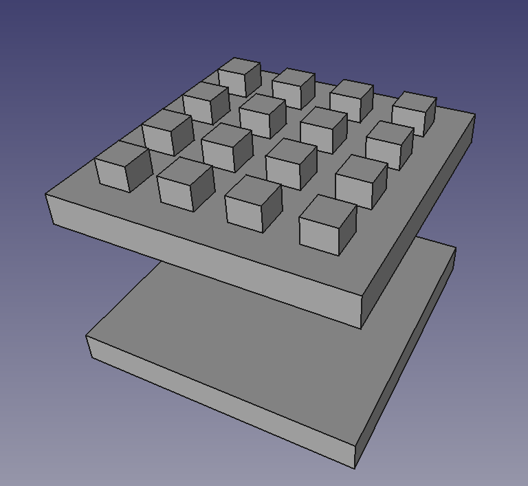
The top layer would be castellated, so the spherical probe can measure the tops (Z) and also the X and Y edges of each projection. The layers underneath can be piled up so we can take those X, Y, and Z measurements at all Z heights in the RepRap. The result would be a 3D cuboid lattice of (X, Y, Z) coordinates throughout the entire build space of the RepRap. Because of inaccuracies in the construction of the RepRap these would not quite correspond to the true (X, Y, Z) coordinates of the calibration stack. The small differences would represent a full spatial compensation for all the RepRap’s inaccuracies: axes not quite perpendicular; non-linearities in the drives; wrong steps-per-mm of some or all the drives; axes not straight; and so on and so on. (Well. Not quite all. Small sharp discontinuities in movement that quickly reverted would not be picked up. But that is a rare error.) We would have a 3-dimensional pattern of short vectors a bit like this:
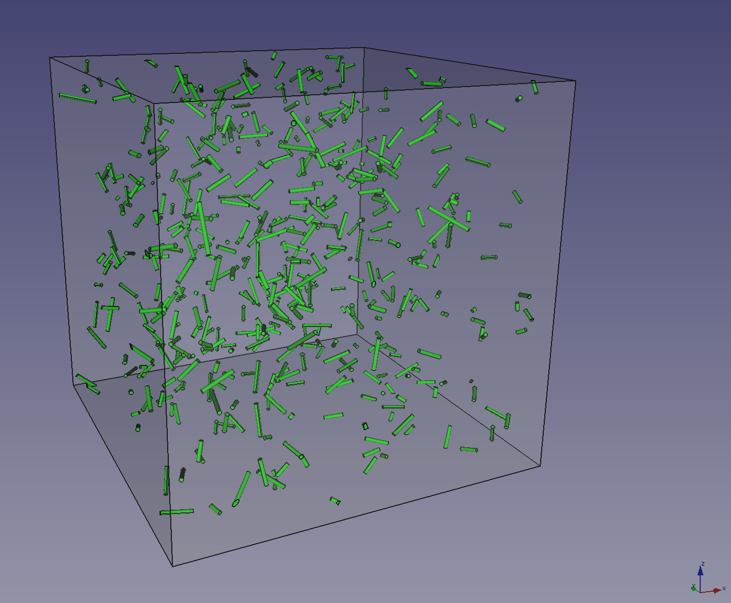
(In practice the pattern would be on a more regular grid and the vectors would be much shorter; the vectors in the picture have random positions and lengths.) At one end of each vector is a point in (X, Y, Z) space where we want the machine to be. At the other end is the point in the machine’s coordinates to which we have to move it in order to achieve that position.
Now. As long as the RepRap is repeatable, it no longer has to be particularly accurate because we can use the map of space we have made to correct every single inaccuracy in the machine in its entire build volume by transforming the input G-Code (X, Y, Z) coordinates to the machine’s corrected coordinate system. This would be done on the fly by the microcontroller in the RepRap in just the same way that bed and axis compensation are done now. Here a great strength of 3D printing comes to our advantage: it is a low-force process (unlike CNC machining) and so it is much easier to make its movements repeatable.
How the ℝ3 to ℝ3 interpolation transform was done would depend on how much computer power could be devoted to it. The simplest scheme would probably be to decompose the spatial cube grid into tetrahedra (or maybe use the Delaunay triangulation) and then to use linear barycentric coordinates in the volume of each tetrahedron. I think this would work quite well, and be fast in execution. However, it would give discontinuous derivatives of position at the surfaces of the tetrahedra, which might (subtly) manifest as a slight pattern on the surface of printed objects wherever the object’s surface intersected a tetrahedron’s face. The positions themselves would be continuous, of course, but – for example – as the print head moved in what should be a straight line using the mapping, the “straight” line might have a slight change of direction when it crossed a boundary. A more elegant (though computationally more expensive) solution would be to use my late friend Robin Sibson’s method of Natural Neighbour Interpolation. That would give a beautifully smooth interpolation based on the Voronoi diagram of the measured points which would also have a continuous derivative.
Connect with us
Keep up to date on the latest RepRap Ltd news:
As you say, this wouldn’t work with any transient or dynamic nonlinearity, such as compliance or hysterisis – how about some method of measuring true position of the nozzle and feeding it back to have closed loop control of the system?
Something like using ultrasonic or laser distance sensors, or an optical flow sensor, or computer vision from a couple of webcams? Admittedly you’d need to calibrate most of these with known good measurements, but not really any more than this method I think?
Yes – closed loop is another possibility, though at the expense of considerably more complexity (all this adds to an existing open-loop machine is one ball bearing). But it’s not too hard to design a rigid mechanism without backlash/hysterisis. What is hard is to manufacture and assemble it very accurately, in particular if you are using 3D printing to make components with an accuracy of only, say 200 microns. I have always liked the idea of making a really solid, but cheap and simple machine, and then putting all the accuracy into easily-changed software, which is what this does.
Really clever implementation! Do you have the math on the significance of probing errors, i.e. microns of triggering distance, manufacturing tolerances in the ball bearing and nozzle, slight eccentricity of nozzle bore due to wear, positioning error of the ball bearing with respect to the nozzle etc, relative to the magnitude of the positioning errors that this technique would otherwise compensate for? Also curious how these positioning errors compare geometry errors arising from extrusion non-linearities, my gut tells me that the latter may be more significant, at least for well-implemented Cartesian style printers.
No – I don’t yet have the numbers (only thought of this three days ago…). Some will be available from manufacturers, of course. But – because errors can accumulate from so many sources – I think that an empirical approach to measuring them, again with calibration objects, would probably be the best approach.
Extrusion variability is another source of error in printed parts. But I think it is more akin to errors from surface roughness, contrasted with errors in bulk geometry like a flat surface being slightly curved. My scheme is really intended to address the latter.
This is so interesting, any ideas how this could be implemented in a production printer?
It would need the printer to have open-source firmware. The coordinate measuring function might just about be implementable just using GCodes if the set were rich enough (like those in RepRapFirmware – https://reprap.org/wiki/RepRap_Firmware), but to do the correction mapping would definitely require the internals of the firmware to be modified. Most firmware already implements transforms between the coordinates in GCodes and what the machine actually does to allow for bed levelling and the like, so there’s usually a function call in the appropriate place. The function called would have to be changed to implement the full 3D to 3D interpolation, which would be quite a significant bit of software in its own right. It should not be too difficult for a fast 32-bit processor, but an 8-bit one would struggle, I think.