DRAFT – these instructions are not final, and are likely to change.
Effector plates
You will need the following parts:
| # |
Component |
Qty |
Type |
| 1223 |
Effector plate (MDF) |
1 |
Lasercut |
| 1233 |
Effector |
1 |
Lasercut |
| 1234 |
Effector top plate |
1 |
Lasercut |
| 1184 |
M3x16mm hex head screw |
6 |
Fastener |
| 1186 |
M3x16mm button head screw |
2 |
Fastener |
| 242 |
M3x16mm cap head screw |
1 |
Fastener |
| 212 |
M3 washer |
2 |
Fastener |
| 204 |
M3 Nyloc nut |
1 |
Fastener |
|
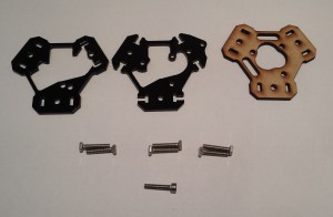 |
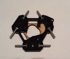
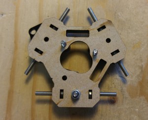
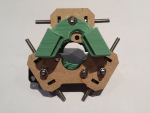
NOTE: The ‘Effector plate’ is the bottom of the three plates, and is on the right in the picture above, made from laser cut MDF. The ‘Effector’ is the middle plate, and in the middle of the above picture. It has slots for the hex head screws. The ‘Effector top plate’ is on the left in the picture above. It has the word ‘TOP’ laser cut into it.
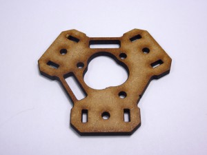
| Take the effector plate, and orientate it as shown. Check the ducts and holes are in the same place. |
 |
| Lay the effector onto the effector plate, as shown. |
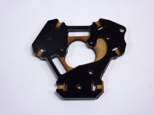 |
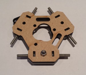
| If you have problems working out which way around, or up, the plates go, there is a notch on the side of each of them, which should line up. See this in the middle of this picture. |
 |
| Place the M3x16mm hex head screws into the slots. |
 |
| Lay the effector top plate onto the effector and put the M3x16mm cap head screw through the hole as shown. |
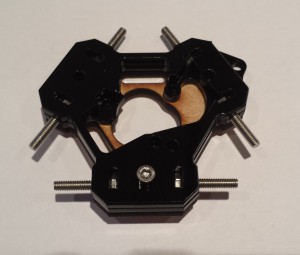 |
| Turn the effector over, and secure the effector plates together using the M3 Nyloc nut. |
 |
| Fit an M3 washer to each M3x16mm button head screw, then fit these as shown. These will need to be screwed into place as the holes are an interference fit. |
 |
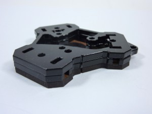
| The effector should look like this from the bottom. |
 |
Ducts
You will need the following parts:
| # |
Component |
Qty |
Type |
|
Effector |
1 |
Assembled |
| 1242 |
Fan spacer |
1 |
Printed |
| 1241 |
Fan duct |
1 |
Printed |
| 1247 |
Nozzle duct |
1 |
Printed |
| 241 |
M3x20mm cap head screw |
1 |
Fastener |
| 242 |
M3x16mm cap head screw |
2 |
Fastener |
| 204 |
M3 Nyloc nut |
1 |
Fastener |
| 258 |
M3 nut |
2 |
Fastener |
|
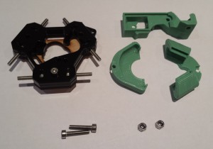 |
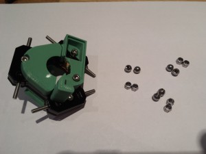
NOTE: The ‘Fan spacer’ is the top printed part in the above picture. The ‘Fan duct’ is the printed part on the left, and the ‘Nozzle duct’ is the printed part on the right.
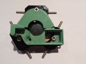
| Attach the fan spacer and fan duct to the effector as shown with the M3x16mm cap head screws. |
 |
| Fit the M3x20mm cap head screw through the left hand hole in the fan spacer. |
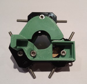 |
| Secure the nozzle duct to the underside of the effector as shown, using the M3 nut. Use an M3 Nyloc and M3 plain nut to secure the fan spacer. |
 |
Connecting rod joints
You will need the following parts:
| # |
Component |
Qty |
Type |
|
Effector |
1 |
Assembled |
| 204 |
M3 Nyloc nut |
6 |
Fastener |
| 1191 |
Threaded ball |
6 |
Hardware |
|
 |
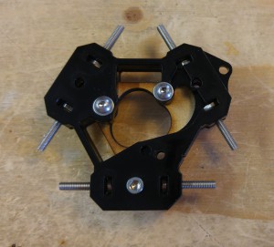
| Onto each of the six hex head screws, fit a Nyloc nut and threaded ball.Before continued use, the balls should be locked onto the threads with an effective thread locking compound (such as Loctite, or we find superglue works very well although one has to be screwing the ball on). If you prefer to leave this until the machine is built, (in case you need to go back and fix build errors), then leave until after the commissioning stage (which includes a reminder). |
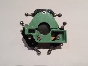 |


