DRAFT – these instructions are not final, and are likely to change.
Logo
You will need the following parts:
| # |
Component |
Qty |
Type |
| 1231 |
Front panel |
2 |
Lasercut |
| 1260 |
Logo |
2 |
Printed |
|
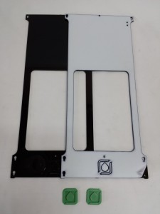 |
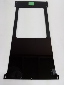
NOTE: ALL acrylic parts come with a protective covering on them. Remove this from the acrylic parts, before assembling them.
| Peel the protective covering from the panels, then push out the acrylic parts where the printed logo will fit. Finally, push the logo into position. This is best achieved by placing the panel face down on a flat, solid surface and gently pushing the logo into place. |
 |
Endstops
NOTE: Kits supplied after mid-August 2015 are NOT supplied with M2.5x10mm screws to mount the microswitches. Use 3 x cable ties to mount them, as shown in the last step below. This is more effective than using the screws!
You will need the following parts:
| # |
Component |
Qty |
Type |
| 1231 |
Front panel |
2 |
Lasercut |
| 1235 |
Side panel |
1 |
Lasercut |
| 185 |
Microswitch |
3 |
Electronics |
| 461 |
M2.5x10mm cap head screw |
6 |
Fastener |
|
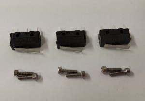 |
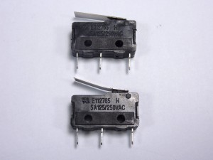
| Trim the microswitch levers making them flush with the body of the microswitch; ideally do this with some tin shears or good pliers, but it is possible to cut them with a good, big, strong, sharp pair of scissors! Also, bend the levers up a little, with the bend in the middle, not from the lever end. This needs to be done to ensure they are activated by the carriage. |
 |
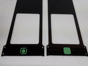
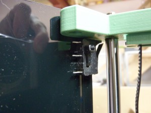
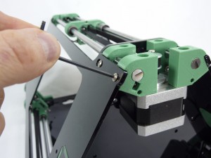
| Fit two microswitches to the side panel. Note which side to fit the microswitches from the photograph, and ensure the lever points to the top of the panel. |
 |
| Fit the third microswitch to one of the front panels. (Holes are in opposite side, compared to picture.) |
 |
| If you have problems with the screws, you can alternatively use a cable tie. This holds the microswitch securely, so long as it is done up tight. If the cable tie is fitted from the inside, put the ‘head’ of the cable tie at the top of the microswitch, or the carriage will hit it before the microswitch is activated. Or fit the cable tie from the outside. |
 |
Base plate
You will need the following parts:
| # |
Component |
Qty |
Type |
|
Motor assemblies |
3 |
Assembled |
| 1206 |
Base plate |
1 |
Lasercut |
|
Picture to come |
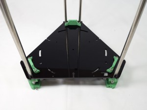
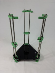
Slide the base plate along the bars to each motor assembly in turn. Start with the side nearest the rectangular slot to ensure the base plate is correctly orientated. The rectangular slot is visible on the left side of the base plate in this picture.
Double check your assembly and verify it matches the photograph shown. Fitting the base plate upside down will cause problems mounting the electronics and wiring looms. |
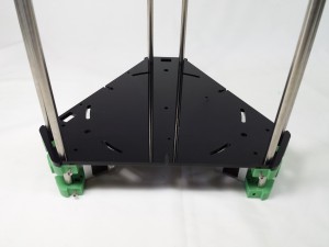 |
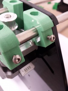
| Once all three motor assemblies are in place, all motors should be flat against the base plate. |
 |
Bed mounting brackets
You will need the following parts:
| # |
Component |
Qty |
Type |
|
Base plate |
1 |
Assembled |
| 1245 |
Bed mounting bracket |
3 |
Printed |
| 112 |
M3x25mm cap head screw |
6 |
Fastener |
| 258 |
M3 nut |
6 |
Fastener |
|
Picture to come |
| For each of the three bed mounting brackets, push two cap head screws through the mounting holes, then place this assembly onto the base plate as shown. |
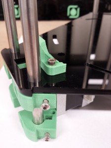 |
| Secure each bed mounting bracket using two M3 nuts below the upper motor brackets. |
 |
| The base should now look like this. |
 |
Side panels
You will need the following parts:
| # |
Component |
Qty |
Type |
|
Base plate |
1 |
Assembled |
|
Front panel |
2 |
Assembled |
|
Side panel |
1 |
Assembled |
|
Carriages |
3 |
Assembled |
|
Idler brackets |
3 |
Assembled |
| 1186 |
M3x16mm button head screw |
3 |
Fastener |
| 258 |
M3 nut |
3 |
Fastener |
|
Picture to come |
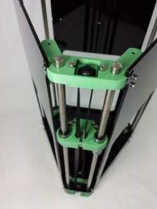
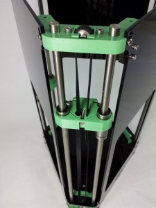
| Slide each carriage assembly onto a pair of bars. The long series bearings should be on the right side of each carriage. |
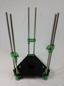 |
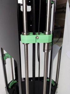
| Slide each idler assembly onto a pair of bars as shown. The bars should protrude approximately 5mm above the idler assemblies. This dimension is not critical. |
 |
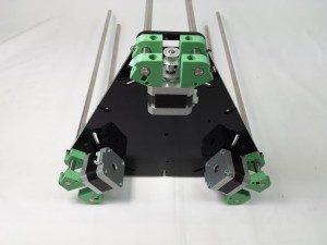
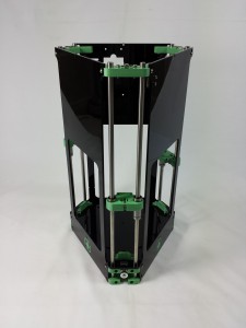
| Fit each panel in turn. The side panel’s notched pillar must be nearest the rectangular slot in the base plate (these features will help to route the cables later in the build). The front panels should be fitted with the logos facing outwards. When viewed from above, the single microswitch should be on the right hand panel, with the pair of microswitches at the back. |
 |
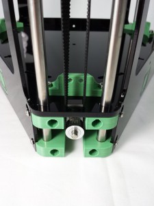
| On each motor mount, fit one M3 nut into the nut trap underneath, and secure the panel with one M3x16mm button head screw |
 |
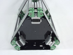
| Check motor orientation. The two motors either side of the side panel (which has holes in it to connect cables to the electronics) should have their motor wiring connectors facing AWAY from the panel, to leave space for the wiring. If it is not like this, simply unscrew the four motor screws, and flip the motor over. The orientation of the third motor’s connector does not matter. |
 |
Drive belts
You will need the following parts:
| # |
Component |
Qty |
Type |
|
Fisher |
1 |
Part-assembled |
| 337 |
MXL belt (cut to a length of 900mm) |
3 |
Hardware |
|
Picture to come |
| Ensure the idler is at it’s lowest point by unscrewing the cap head screws retaining it from the top. |
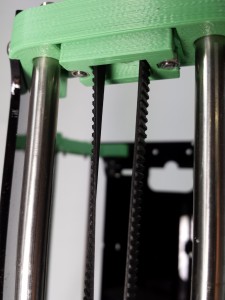 |
| Run the belt over the idler bearings, toothed side up. |
 |
| Slip the belt through each slot in the carriage. Add a 180 twist to the belt going through the larger opening in the carriage (on the left side). |
 |
| Run the belt down around the pulley and back up towards the carriage. |
 |
| Engage the ends of the belt and pull them up through the slot in the carriage. This will require a reasonable amount of force, and lock the belt into the carriage. Do not tension the belt yet; you will need to release the top of the side panels to fit the top plate, later. Anytime you remove the side panels, release the tension in the belt first, or the idler bracket will be pulled downwards. |
 |
| Repeat the above steps for all three axes. |
|


