DRAFT – these instructions are not final, and are likely to change.
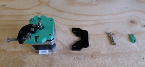
Drive block
You will need the following parts:
| # |
Component |
Qty |
Type |
| 408 |
NEMA 17 stepper motor |
1 |
Electronics |
| 242 |
M3x16mm cap head screw |
2 |
Fastener |
| 1239 |
Drive block |
1 |
Printed |
| 1255 |
Drive block spacer |
1 |
Lasercut |
|
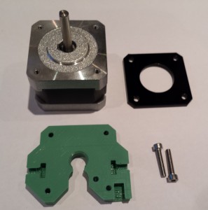 |
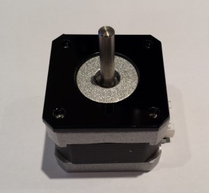
| Place the motor onto the spacer. |
 |
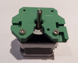
| Attach the drive block using the two cap head screws as shown. |
 |
Idler bearing
You will need the following parts:
| # |
Component |
Qty |
Type |
| 279 |
623 bearing |
1 |
Hardware |
| 702 |
M3x10mm cap head screw |
1 |
Fastener |
| 258 |
M3 nut |
2 |
Fastener |
| 212 |
M3 washer |
2 |
Fastener |
|
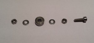 |
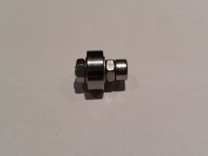
| Assemble the idler bearing with a nut and washer on each side of the bearing. |
 |
Lever
You will need the following parts:
| # |
Component |
Qty |
Type |
|
Idler bearing |
1 |
Assembled |
| 1237 |
Lever |
1 |
Lasercut |
| 1238 |
Lower lever |
1 |
Lasercut |
| 702 |
M3x10mm cap head screw |
2 |
Fastener |
|
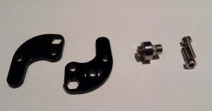 |
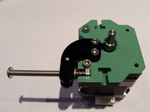
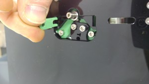
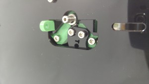
| Slide the lever into place, insert the idler bearing assembly, then fit the top lever. Secure at the pivot point with a cap head screw. Finally, screw the remaining cap head screw up through both levers. The hole in the top lever is smaller than in the lever, such that the screw will bite into the plastic. |
 |
Spring assembly
ou will need the following parts:
| # |
Component |
Qty |
Type |
| 650 |
M4x35mm button head screw |
1 |
Fastener |
| 1193 |
M4 nut |
3 |
Fastener |
| 1185 |
M4 washer |
3 |
Fastener |
| 1250 |
Idler spring |
1 |
Hardware |
|
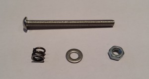 |
| Fit the washer, spring and nut (in that order) to the button head screw. |
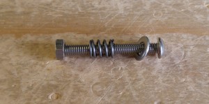 |
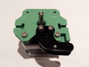
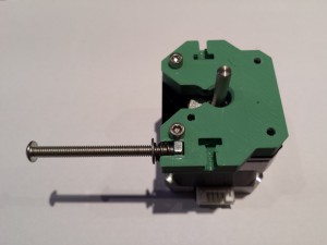
| Slide the assembly into the drive block as shown. |
 |
Hobbed insert
You will need the following parts:
| # |
Component |
Qty |
Type |
| 1181 |
Hobbed insert |
1 |
Hardware |
| 1183 |
M3x3mm set screw |
1 |
Fastener |
|
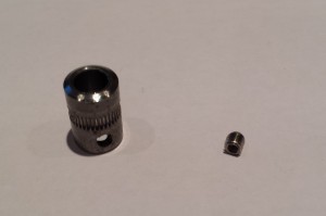 |
| Slide the hobbed insert onto the motor shaft, then slip some filament through the drive block, to engage with the teeth on the hobbed insert. Add a small drop of thread lock (or superglue) to the set screw, then screw it into the hobbed insert and tighten onto the flat of the motor shaft. Take care not to strip the head of the screw. |
 |
Mounting the drive
You will need the following parts:
| # |
Component |
Qty |
Type |
|
Fisher |
1 |
Part-assembled |
|
Extruder drive |
1 |
Assembled |
| 1236 |
Drive spacer |
1 |
Lasercut |
| 152 |
Tongue |
1 |
Printed |
| 241 |
M3x20mm cap head screw |
2 |
Fastener |
|
 |
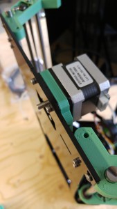
| Insert the drive spacer between the extruder drive assembly and side panel, then secure using the two cap head screws. |
 |
| Push the bowden end into the drive block. This should be a snug fit. |
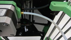 |
| Ensure the bowden start is fully inserted. |
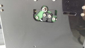 |
| The tongue is used to retain the bowden tube during printing. Take care to orientate the tongue as shown. |
 |
| Push the tongue fully into the slot. |
 |
| Finally, push the extruder thumbwheel onto the end of the stepper motor shaft. This allows you to move the extruder manually, which is helpful when loading filament. |
Picture to come |


