Goal
TIP: Click on pictures in the instructions to see a larger version.
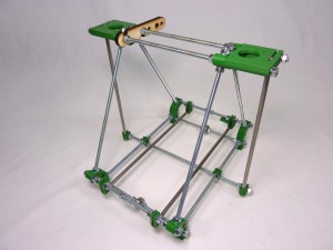
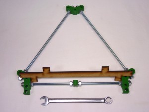
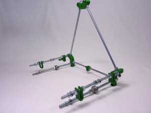
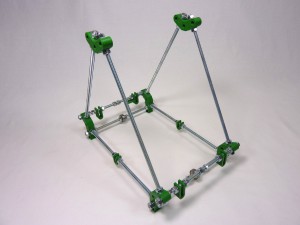
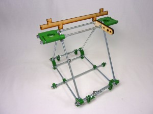
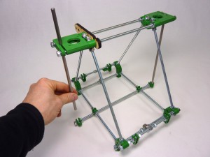
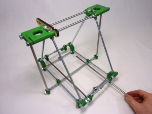
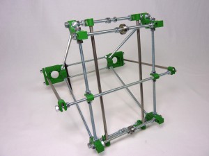
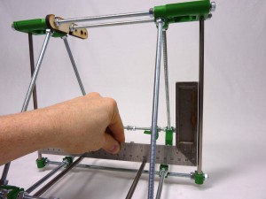
| By the end of this stage, your machine should look like this. |
 |
Frame triangles
TIP: Click on the bold names of the printed parts in the component lists. This opens a new window, showing the part in the Github stl viewer, so you can identify the part more easily.
| # |
Component |
Qty |
Type |
| 610 |
frame-vertex |
2 |
Printed |
| 281 |
frame-vertex-foot |
4 |
Printed |
| 209 |
bar-clamp |
2 |
Printed |
| 875 |
M6x250mm studding |
6 |
Hardware |
| 557 |
M6 nuts |
28 |
Fastener |
| 558 |
M6 serrated washers |
28 |
Fastener |
| 600 |
Measuring jig (3mm MDF) |
1 |
Laser cut |
|
 |
Frame triangle assembly x 2
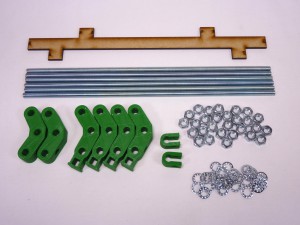
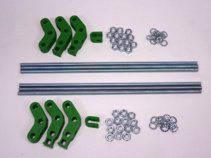
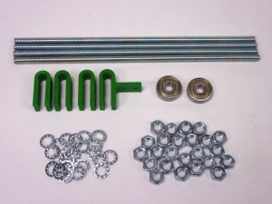
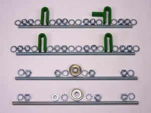
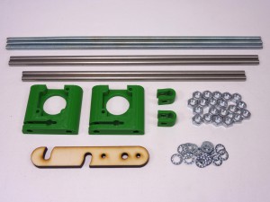
| These parts are used to build two frame triangles. Split the components equally in half. |
 |
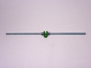
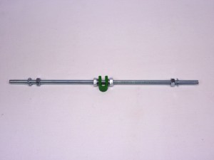
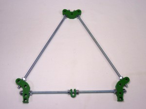
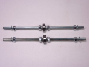
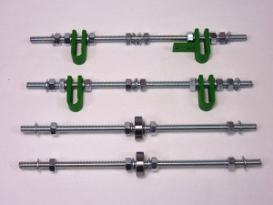
| Starting at the base of the triangle, take one piece of M6 studding, and slide a bar-clamp to the centre of the rod. Put an M6 serrated washer and M6 nut either side of the bar-clamp, and very loosely screw the nuts up to the bar-clamp. |
 |
| Put an M6 nut and M6 serrated washer on each end of the M6 studding. |
 |
| Then push a frame-vertex-foot on each end. Note the orientation of these printed parts. |
 |
| Put an M6 serrated washer, and M6 nut on each end of the studding, to hold the printed part on the studding. |
 |
| Take two more pieces of studding, and put an M6 nut then M6 serrated washer on each end. |
 |
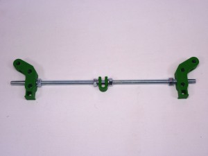
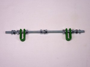
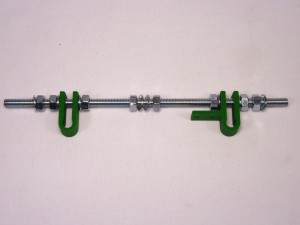
| Connect them to the frame-vertex-foot. Where the studding meet at the apex of the triangle, use the frame-vertex, with no foot. |
 |
| On each side of each vertex, there should be an M6 serrated washer and M6 nut. |
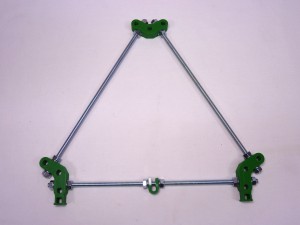 |
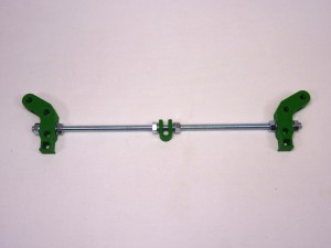
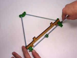
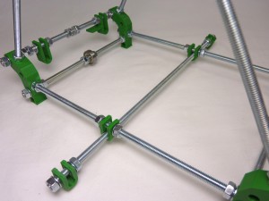
| Now repeat same for second triangle. Your frame triangles should end up looking like this. |
 |
Fine tune triangle sizes
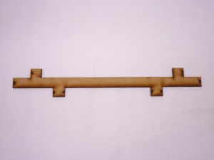
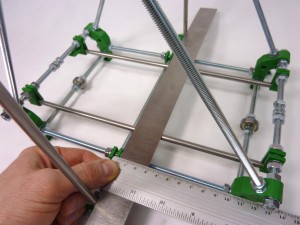
| The nuts on both frame triangles need to be tightened to make them rigid. The distance between the vertices is critical. The kit has a laser-cut measuring template provided. Use this to make checking the gaps easy, or use a ruler. Please, be patient, give it time, this is very important step. |
 |
| For each frame, measure the distance between the vertices on all three sides. The distance you should be aiming for is 207mm. But more important is to make them all six the same. The better aligned your frame is, the better your prints will be when printing large and/or tall objects. |
 |
| Gently tighten all the M6 nuts ensuring the distance between vertices of 207mm is maintained. Try to get this as accurate as possible, with less than a millimetre of variation in all. |
 |
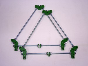
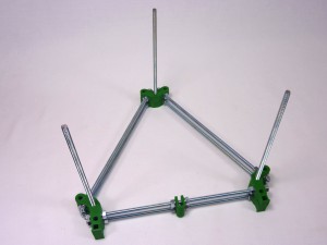
| You can check the accuracy of your triangle frames by placing them on top of each other. |
 |
Cross bars
| # |
Component |
Qty |
Type |
| 616 |
y-bar-clamp |
3 |
Printed |
| 618 |
y-bar-clamp-endstop |
1 |
Printed |
| 881 |
M6x185mm studding |
4 |
Hardware |
| 557 |
M6 nuts |
24 |
Fastener |
| 558 |
M6 serrated washer |
24 |
Fastener |
| 137 |
626 Bearing |
2 |
Hardware |
|
 |
| The above parts are used to build four cross bars, which join the triangles together. The two ‘bottom’ bars are identical. The two ‘top’ bars are similar, but one has a y-bar-clamp with an extra tab, which is used to mount the Y axis endstop. |
 |
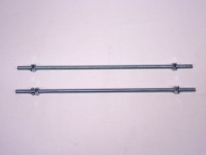
| It is easiest to start in the middle and work outwards, so you don’t have to screw the M6 nuts all the way along the studding. For each of the bottom bars, push on one 626 bearing. Then fit a serrated washer, 2 x M6 nuts, and serrated washer. Repeat on the other side of the bearing. Then build a second bar, just like the first. |
 |
| For the first top bar, starting from the middle of the M6 studding, fit: serrated washer, two M6 nuts, serrated washer, y-bar-clamp, serrated washer, two M6 nuts, serrated washer. Repeat in the other direction from the centre: serrated washer, two M6 nuts, serrated washer, y-bar-clamp, serrated washer, two M6 nuts, serrated washer. |
 |
| For the other top bar, it’s the same as the above, except replace one of the y-bar-clamps with the y-bar-clamp-endstop. Mount it with the tab facing towards the centre of the bar. |
 |
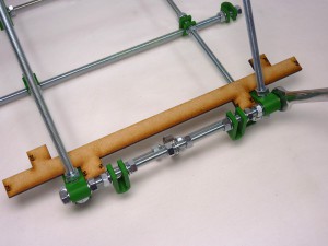
| Your cross bars will now look like this: |
 |
Assemble the frame
| # |
Component |
Qty |
Type |
|
Frame triangle assembly |
2 |
Assembled |
|
Cross bar assembly |
4 |
Assembled |
| 169 |
z-motor-bracket |
2 |
Printed |
| 209 |
bar-clamp |
2 |
Printed |
| 509 |
extruder-drive-holder |
1 |
Laser cut |
| 882 |
M6x285mm threaded rod |
3 |
Hardware |
| 890 |
6mm x 235mm smooth rod (Z axis) |
2 |
Hardware |
| 888 |
6mm x 270mm smooth rod (Y axis) |
2 |
Hardware |
| 557 |
M6 nut |
20 |
Fastener |
| 558 |
M6 serrated washer |
20 |
Fastener |
|
 |
Mounting the cross bars
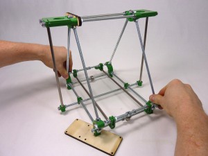
| Take the cross bar assemblies, and fit them into one of the triangles. The cross bars with the bearings go on the bottom. The cross bar with the y-bar-clamp with the extra tab should go at the back, on the right. |
 |
| Put an M6 serrated washer and M6 nut on the end of each bar, as it passes through each frame-vertex-foot. |
 |
| Then fit the second triangle to the other end of the cross bars, with an M6 serrated washer and M6 nut on the end of each bar, as it passes through each frame-vertex-foot. |
 |
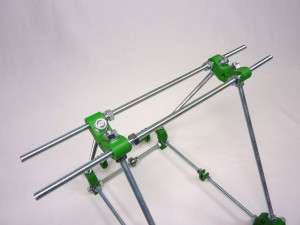
| Slide two M6x285mm threaded rods through the top frame vertices. Slide each rod through one vertex, then fit one M6 serrated washer, two M6 nuts and another serrated washer. |
 |
| Slide the rod through the opposite vertex, and equalise the length the rods stick out. |
 |
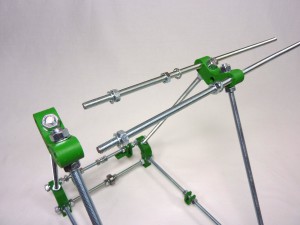
| Slide a Z motor mount onto each end of the top rods. This may need a little force as the holes through the z motor mounts tend to be quite a tight fit on the M6 threaded rods; it’s a good idea to make sure you can push the spare length of M6 threaded rod into each of the z motor mount holes before trying to fit them to your frame. |
 |
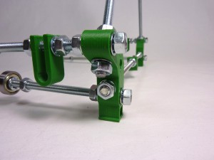
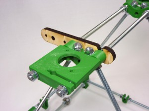
| Add the filament drive bracket so it is inside the left z-motor-mount and frame-vertex, and is held against it by the inner nuts and washers. The front slot next to the rounded end goes upwards, the middle slot goes at the back and downwards, as shown |
 |
| Before tightening the M6 nuts on the top rods, slide the last M6x285mm threaded rod through the two bottom bar clamps. You do not need M6 nuts or washers either side of the bar-clamps. At each end of this bottom rod, fit an M6 nut, an M6 serrated washer, a bar clamp, an M6 serrated washer, and another M6 nut. |
 |
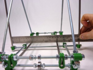
| At this stage, the frame should be quite loose, so just jiggle everything around until all the angles look about right. Once you are happy with this step, you can tighten the nuts on the cross bars. The distance between the frame vertices along the cross bars should be 146mm. |
 |
| Check the spacing between the top bars is also 146mm. |
 |
Fit the Z and Y axis smooth rods
| You can now slide the two Z smooth rods (length 235mm) into place. When tightening the M6 nuts on the top cross bars, please note that you do not need to tighten the nuts which clamp against the Z smooth rods too much, only enough to stop the smooth rod from sliding down. |
 |
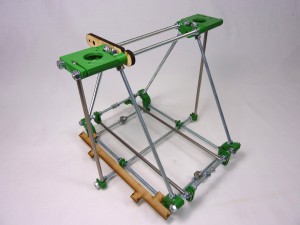
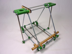
| Before tightening the bar clamps on the bottom cross bar, slide the Y axis smooth rods (270mm) into place. Current Huxley kits have 4 x 270mm smooth rods (2 for the Y axis, 2 for the X axis). Early kits have 2 x 270mm rods for the Y axis, and 2 x 265mm rods for the X axis. Make sure you use 2 x 270mm smooth rods for this step. |
 |
Aligning the frame
| Place the frame on a flat surface. Wooden furniture, by and large, is not flat. But thick kitchen worktops are very flat. Check all triangle sides (x6) are equal. |
 |
| Check cross bars (x6, between vertices of triangles) are all equal. |
 |
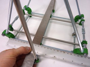
| Adjust base diagonal to square the base. Measure across the corners of frame-vertex-foot (upside down is easiest). Push the frame so it is square. |
 |
| If the frame doesn’t sit flat on the table (assuming a flat table), use a shim to lift the low leg up, and press the frame on the corners that are high, so the base square sits flat on your surface. |
 |
| Check the frame triangles are square. Push the frame along the top bars if it is not, until they are square. |
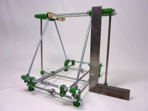 |
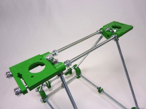
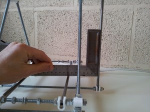
| Square the Z rods front/back. Use a straight edge, touching one side of the Z rods. Measure from the edge of the straight edge to the frame-vertex. It should be around 100.5mm. |
 |
| Equalise the length by moving the frame clip along the triangle bottom rod. Repeat this a number of times, switching sides, to get it accurate. You can also look side-on at the Z bars, and make sure they are parallel. If they are not, check the base (diagonally between the frame-vertices-foot) is square. |
 |
| Square the Z rods left/right, using a set square. Use a set-square to get the angle of the Z smooth rods correct. Push the lower bar through the frame clamps to adjust. |
 |
| Measure the distance between the Z rods top… |
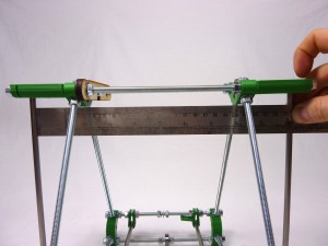 |
| …and bottom, to check they are parallel. |
 |
| You can now tighten the M6 nuts along the bottom cross bar. You will have to remove the Z rods to fit the X axis; only undo the outer nut on each side, you should then be able to put them back in without moving the frame too much, though you may need to check it again after fitting the X axis. |
 |
TIP: You can revisit this checklist at any point during building and running your machine, to check your frame is still square.
Frame finished
| You will now have an assembled RepRapPro Huxley frame. |
|


