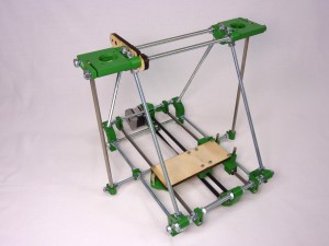
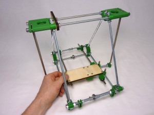
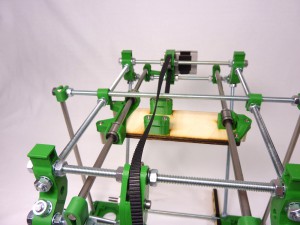
Goal
| By the end of this stage, your machine will look like this: |
 |
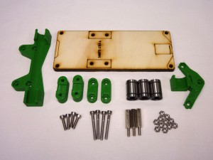
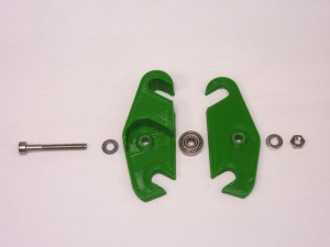
Y-carriage
| # |
Component |
Qty |
Type |
| 742 |
bearing-holder-fixed |
1 |
Printed |
| 719 |
bearing-holder-float |
1 |
Printed |
| 273 |
y-belt-clamp-1 |
2 |
Printed |
| 740 |
y-belt-clamp-2 |
2 |
Printed |
| 248 |
Y frog (6mm plywood) |
1 |
Laser cut |
| 207 |
LM6UU Linear bearing |
3 |
Hardware |
| 818 |
M3x18mm Male/Female Stand Off |
3 |
Electronics |
| 257 |
M3x12mm cap head screw |
4 |
Fastener |
| 112 |
M3x25mm cap head screw |
4 |
Fastener |
| 258 |
M3 nut |
11 |
Fastener |
|
 |
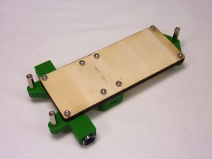
Y-carriage assembly
| Push the linear bearings into the bearing holders from the side. Don’t try to clip them in from the top. They should be an interference fit and should stay where they are put. |
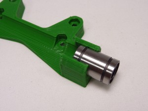 |
| When correctly fitted, the linear bearing should protrude by the same amount from each end of the bearing holders. |
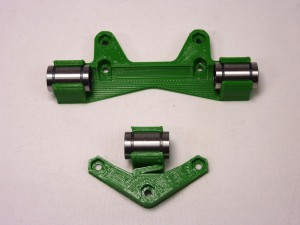 |
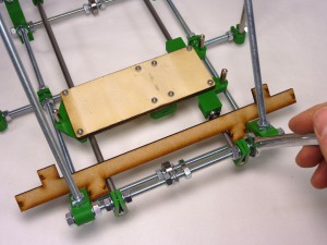
| Assemble the parts of the Y carriage as shown. Use the M3x12mm cap head screws and M3 nuts for the bearing holders. The screws should be inserted from the top of the laser cut frog (the side without the markings). The nuts go in the captive holes in the bearing holders. |
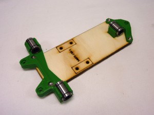 |
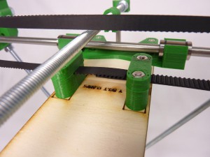
| Use the M3x25mm cap head screws and M3 nuts for the y-belt-clamps. The taller part goes next to the laser cut frog, with the notch upward. The smaller part has captive holes for the nuts. |
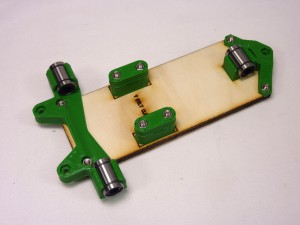 |
| Use three more nuts in the captive holes, and screw in the standoffs from the other side of the carriage. |
 |
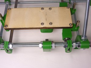
Y-carriage mounting
| Adjust the gap between the 270mm Y rods at both ends so they are parallel and their outer edges are 114mm apart. Don’t tighten their clamps yet. |
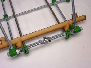 |
| Slide the 270mm Y rods partly out of the machine, put the sled onto them, and refit their free ends into the frame. The Y-carriage should be orientated so the side with two bearings is on the same side as the y-rod-clamp with the long tab. |
 |
| Slide the Y sled back… |
 |
| … and forth. It should run completely freely. If it doesn’t, that means that the rods are not quite parallel – move their ends a little bit using the nuts either side. |
 |
| Gradually tighten the ends of the rods, checking for free running right from end to end all the while as you do so. |
 |
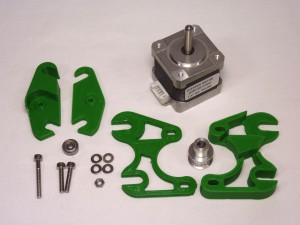
Y motor and idler brackets
| # |
Component |
Qty |
Type |
| 619 |
y-idler-bracket-left |
1 |
Printed |
| 621 |
y-idler-bracket-right |
1 |
Printed |
| 623 |
y-motor-bracket-left |
1 |
Printed |
| 629 |
y-motor-bracket-right |
1 |
Printed |
| 279 |
623 bearing |
1 |
Hardware |
| 242 |
M3x16mm cap head screw |
2 |
Fastener |
| 112 |
M3x25mm cap head screw |
1 |
Fastener |
| 212 |
M3 washer |
4 |
Fastener |
| 258 |
M3 nut |
1 |
Fastener |
| 130 |
NEMA 14 stepper motor |
1 |
Hardware |
| 389 |
18-tooth MXL pulley and grub screw |
1 |
Hardware |
|
 |
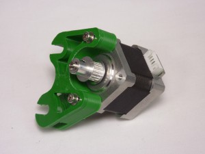
Motor end
| The pulley has a threaded hole in it for a grub screw to hold it on the motor shaft. This should be supplied fitted, but if not, screw the grub screw into the pulley a short distance. |
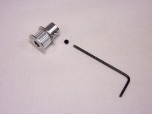 |
| Take an MXL pulley and push it onto the motor shaft, taking care to note its orientation. Install the pulley with the pulley teeth closest to the motor body. The motor shaft has a flat on it; align the grub screw with this, and tighten the grub screw using a 1.5mm Allen key. |
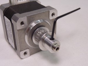 |
| Leave a gap of about a millimetre between the pulley and the motor body, so the pulley can turn freely, and not rub against the motor body. |
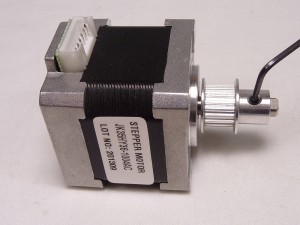 |
| Screw the motor to the Y motor brackets using the two M3x16mm screws with washers under their heads (if the screws are a little short leave out the washers). Note the orientation of the stepper motor. The motor is mounted on slots; these allow for the belt to be tensioned. |
 |
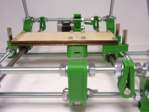
| The Y motor goes at the back of the machine, with the motor to the left when looking from the front of the machine. Fit the the Y motor bracket either side of the 626 bearing, and between the serrated washers on the cross bars. |
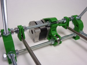 |
| Move the Y sled to be at the same end, and make sure that the motor is positioned so that the bearings line up with the centre of the two holes in the sled that will hold the toothed-belt clamp. Note that the motor connector should point out from the machine. Also check that the motor bracket is vertical. |
 |
| The Y axis motor end will now look like this. |
 |
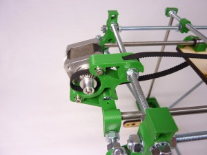
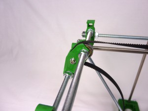
Idler end
| The Y axis idler end is also constructed from two printed parts. Screw them together with the bearing inside as shown, using the 25mm screw. |
 |
| Move the Y sled to the front of the machine (i.e. the opposite end to the Y motor you just fitted) and use the Y belt holes to get the idler bracket in roughly the right place. Fit the the Y idler bracket either side of the 626 bearing, and between the serrated washers on the cross bars. |
 |
| Also check that the motor bracket is vertical. The y-motor-bracket, y-carriage screws and y-idler-bracket should all be in line. Tighten the nuts to hold the Y idler bracket. |
 |
Y axis belt
| # |
Component |
Qty |
Type |
| 337 |
MXL belt |
600mm |
Hardware |
|
Picture here |
NOTE: The MXL belt is usually supplied as one piece, 1.25m long. For the Y axis, you need a piece 600mm long. For the X axis, you need a piece 580mm long, and a piece 40mm long for the X carriage. For this step you just need one 600mm toothed belt. Your belt may have been supplied as a single piece used for both the Y axis and X axis assemblies, so when you cut off the excess belt you’ll want to retain as much as possible of the remainder. So don’t cut this too long!
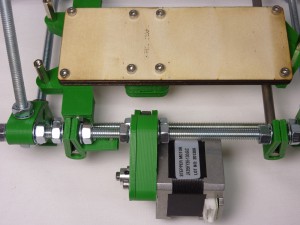
| It’s easiest to turn the printer upside-down to fit the belt. Route the belt through the Y axis motor end, around the toothed drive pulley, and over the 626 bearing. The belt teeth should engage with the pulley. |
 |
| Then along to the idler end. Twist the belt 180°, so that the flat side then goes over the 626 bearing. The belt teeth should face outwards. |
 |
| The belt should go around the 626 bearing, into y-idler-bracket, around the 623 bearing, and back out of the y-idler- bracket. |
 |
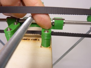
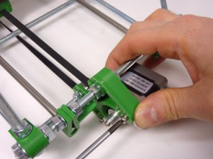
| Loosen one of the belt clamps on the Y carriage. Feed the two ends through the y belt clamps, and pull them tight. Overlap the two ends of the belt. The overlap should be 6 or 7 teeth. |
 |
| Push the overlap into the loosened belt clamp, and hold it with your finger, while you tighten the screws. The belt doesn’t have to be particularly tight – you will adjust the tension with the Y motor, in a minute. Check the belt lines up by eye. The top should be in line with the bottom and the belt should be square where it sits under the clamps. |
 |
| Tighten the y axis belt by loosening the two M3 cap head scews securing the y motor. Pull the motor back in the slots, then retighten the screws. If you run out of adjustment, you need to overlap the belt in the belt clamps at least one more tooth. If you pluck the belt between the 626 bearings (the longest part of the belt, with the twist), you should hear a low note. The belt doesn’t need to be too tight – check that you can still easily move the Y carriage back and forth. |
 |
| This shows the belt fully fitted. Move the y-carriage back and forth, making sure everything on the Y axis stays in line and runs freely, from one end to the other and back. |
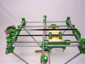 |
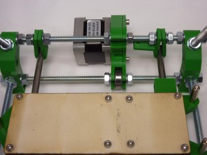
Y axis finished
| Your Huxley should now look like this. |
|


