Goal

By the end of this stage, your machine will look like this: HUX2-z-axis-22

Fitting the X axis

Undo the U-clips that hold the bottom of the Z-axis rods. Only undo the outside nuts – the inside ones need to stay positioned to relocate the rods when you do things up again. HUX2-z-axis-01
Undo the M6 nuts that retain to tops of the rods. HUX2-z-axis-02
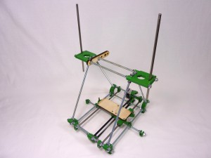
Slide the rods upwards so they are sticking out the top. HUX2-z-axis-03
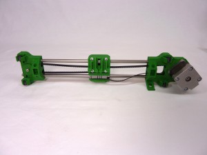
Disconnect one end of the X belt from the X carriage. This will allow you to adjust the width of the X carriage as necessary. HUX2-z-axis-04
Push the Z-axis rods down through the Igus bearings in the ends of the X carriage. HUX2-z-axis-05
Put one Z rod back in its retaining bottom U clip. Adjust the width of the X axis as necessary. Slide them back and forth on the X rods until everything fits, then put the other Z rod back in its U clip. HUX2-z-axis-06
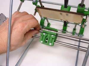
Slide the X axis to the top of its travel, and get the gaps between its ends right there. (This will be a distance that cannot be adjusted.) Gently tighten the two screws projecting from the X-axis idler end until they touch the ends of their rods. Don’t over-tighten them, as that will bend the Z rods. HUX2-z-axis-07
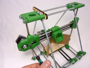
Now slide the X axis back down again, checking that it moves completely smoothly. It may bind for two reasons. First, the X axis may be tilted (like trying to put a drawer in a chest-of-drawers at a slight angle). This doesn’t matter – get it more level and try again. Second, the gap at the bottom of the Z rods may not be quite the same as that at the top. This does matter, and needs to be fixed. To get the bottom Z-rod gap right, carefully move the U clips by undoing and doing up the nuts either side of them. Do this symmetrically. That is to say, if you move the inner nut on the right three-quarters of a turn inwards, do exactly the same with the corresponding nut on the left. It helps to mark one flat on the nuts with a felt-tipped pen so you can keep track of turns. HUX2-z-axis-08
Keep sliding the X axis up and down the rods, and make small symmetrical adjustments as above until it runs completely smoothly. When you’re happy with the movement, Re-fit the X belt. Pull it tight, then slot it in one notch looser. HUX2-z-axis-09
Slacken the screws on the X motor, slide them in their slots to take up the slack on the X belt, and re-tighten them. You can place an object under the X axis to hold it up. HUX2-z-axis-10

Fitting the Z drive

# Component Qty Type
609 z-coupling 4 Printed
130 NEMA 14 stepper motor 2 Hardware
195 5mm x 30mm poly tubing 2 Hardware
511 M5x165mm studding 2 Hardware
276 7mm x 15mm spring 2 Hardware
712 M5 nut 2 Fastener
242 M3x16mm cap head screw 8 Fastener
212 M3 washer 8 Fastener
258 M3 nut 4 Fastener
HUX2-z-axis-15
Next put 4 x couplings together as shown, using a M3x16mm cap head screw, M3 washer, z-coupling printed part and M3 nut for each. The M3 nut sits in the nut trap in the printed part. Assemble loosely. HUX2-z-axis-12
Push the couplings over the poly tubing. Align the slots in the printed parts for each coupling. HUX2-z-axis-13
Slide a coupling onto each motor. Try to align the slot in the coupling with the flat of the motor shaft; this will make the coupling hold centrally. Tighten the screw that holds the coupling on the motor shaft. HUX2-z-axis-14
Place an object on the Y bars to hold the X axis about half-way up its travel. HUX2-z-axis-16
Insert an M5 nut into each slot in the ends of the X axis, and push an anti-backlash spring in under the nut. It can help to use the M5 threaded rod on top of the M5 nut; screw it in a couple of turns and use the rod to hold the nut at the top of the slot, and push the spring in. HUX2-z-axis-17
Screw the M5 studding down through the nut and spring until its top is about 30mm below the Z-motor brackets at the top of the machine. Repeat this for the other end of the X axis. HUX2-z-axis-18
Put the Z motors with their couplings in place on top of the z-motor-mounts and loosely attach them from underneath with two M3x16mm cap head screws with M3 washers under their heads on the motor’s diagonals. Note the orientation of the motor’s wiring connectors; this is important, so the loom fits correctly. HUX2-z-axis-19
Make sure the lower screws on the Z couplings are loose. The coupling should be free to rotate in the space in the z-motor-mount. HUX2-z-axis-20
Screw the M5 studding up into the lower half of each coupling. Leave a small gap (1mm is fine) between the top of the M5 studding and the motor shaft. Tighten the couplings. Tighten the diagonal pairs of screws holding the Z motors. HUX2-z-axis-21
Measure the gap between the Y rods and the bottom X rod with digital callipers. HUX2-z-axis-23
Turn the Z motors by hand to make the gap each side equal. HUX2-z-axis-24

Z axis fitted

Your machine should nowl look like this. HUX2-z-axis-22