Goal

By the end of this stage, your X axis will look like this: HUX2-x-axis-30

X axis rails

# Component Qty Type
316 x-motor-bracket 1 Printed
267 x-idler-bracket 1 Printed
614 x-carriage 1 Printed
884 6mm x 270mm smooth rod (X axis) 2 Hardware
207 LM6UU Linear bearings 3 Hardware
235 Igus 6mm clip bushing 4 Hardware
242 M3x16mm cap head screw 2 Fastener
258 M3 nut 2 Fastener
HUX2-x-axis-06

Note: early Huxley Duo kits came with 2 x 265mm and 2 x 270mm smooth rods. This has been changed to 4 x 270mm smooth rods. If you have 2 x 265mm rods, use them for the X axis. The 270mm rods will work in the X axis, but the Y axis requires the 270mm rods (see Frame assembly).

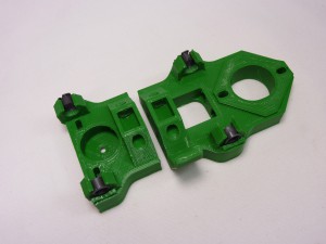
Start by fitting the Igus bushings into the x ends. These bushings need to allow the Z smooth rods to slide easily bt without much slack. In order to achieve this, you will need to fit an Igus bushing into position and slide a smooth rod through it. HUX2-x-axis-01
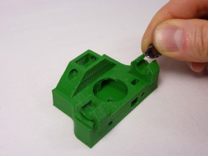
The bushings can be curled up slightly to fit in downwards. The rims are retained by slots in the 3D-printed parts. Do not attempt to put the bushing in with the smooth rod running through them – this will break the printed part. Put the bushing in on their own, then run the rod through afterwards to check them when they are in place. HUX2-x-axis-02
If the fit is too tight, remove the igus bushing, then remove a small amount of material from the X end. Either use the half-round file to remove material, or clamp a 7mm drill in a vice and run the X end up and down it by hand. Take care – it’s better to remove too little and to have to repeat the procedure, than to remove too much irrecoverably. HUX2-x-axis-03
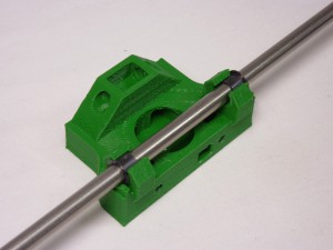
Try the smooth rod through the bushing again. Repeat this procedure for all four bushing positions. HUX2-x-axis-04
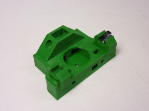
The holes in the two ends of the X axis where the smooth rods will be fitted are very deep and tend to be very tight fitting; you should ream these out before assembly. Clamp a 6mm drill in a vice and run the holes up and down over it by hand. Again take care not to remove too much – you want a snug fit. HUX2-x-axis-07
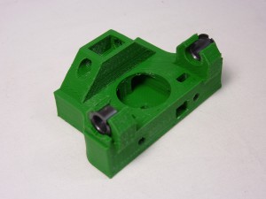
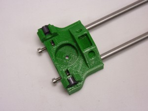
Run a 5.5 mm drill through both Z-axis threaded rod holes (top right in the picture above); these holes must allow the threaded rod to pass through with clearance. HUX2-x-axis-08
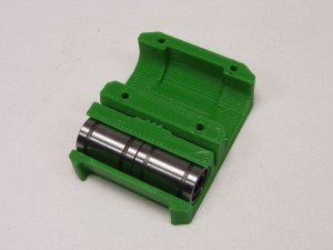
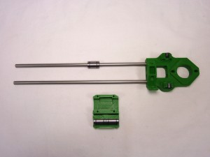
Slide two linear bearings into the bottom of the X carriage from the side, rather than downwards, otherwise you will break the clip. HUX2-x-axis-05
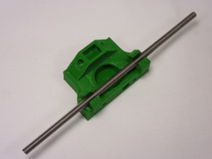
You can now insert the smooth rods into the X motor end, and slide the other linear bearing onto the top rod (you may need to de-burr the end of the rods with a file to get the bearings on). The smooth rods go a LONG way into the motor mount; make sure they are both fully inserted before you go further. HUX2-x-axis-09
As with the Y axis smooth rods, if the linear bearings are a little tight, place the smooth rod into an electric drill, then spin the rod whilst rubbing it with a scouring pad. The linear bearing should slide freely along the rod, but without too much play. HUX2-x-axis-10
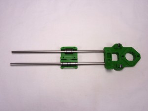
Put the X carriage onto the rods. HUX2-x-axis-11
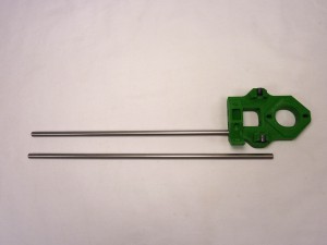
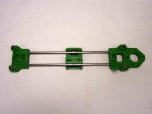
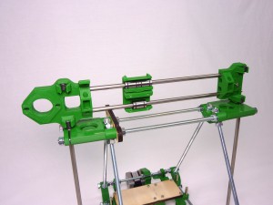
Add the X idler end, at which point your X axis assembly will look like this: HUX2-x-axis-12
Drop two nuts into the slots in the idler, and put two screws into them. Leave them loose. These are used to adjust the gap between the Igus bearings at each end, to match the gap between the Z axis smooth rods, by pushing on the ends of the X axis smooth rods. HUX2-x-axis-13
Set the distance between the clip bearings to be close to the distance between the Z axis smooth rods. A simple way to do this is to place the X axis assembly above the frame, and looking down through the clip bearings, check that they line up with the tops of the smooth rods. The distance should be 260mm. HUX2-x-axis-28

X axis belt

# Component Qty Type
611 idler-cover 1 Printed
337 MXL belt 580mm Hardware
337 MXL belt 40mm Hardware
130 NEMA14 stepper motor 1 Hardware
389 18-tooth MXL pulley and grub screw 1 Hardware
279 623 bearing 1 Hardware
242 M3x16mm cap head screw 3 Fastener
258 M3 nut 1 Fastener
212 M3 washer 2 Fastener
HUX2-x-axis-14
Loop the belt through the idler end as shown. HUX2-x-axis-15
Put an M3x16mm cap head screw through the cover, put the bearing on it, and push the result into the hole in the idler end. Tighten an M3 nut on the back. HUX2-x-axis-16
Loop the other end of the belt through the motor end in a similar manner. HUX2-x-axis-17
As before, the pulley has a threaded hole in it for a grub screw to hold it on the motor shaft. This should be supplied fitted, but if not, screw the grub screw into the pulley a short distance. HUX2-y-axis-14
Push the MXL pulley onto the motor shaft, taking care to note its orientation. Install the pulley with the pulley teeth closest to the motor body. Leave a gap of about a millimetre between the pulley and the motor body, so the pulley can turn freely, and not rub against the motor body. The motor shaft has a flat on it; align the grub screw with this, and tighten the grub screw using a 1.5mm Allen key. HUX2-x-axis-18
Attach the motor to its bracket with two M3x16mm cap head screws, with an M3 washer under each. Like the Y axis, the X axis motor is mounted in slots, so the belt tension can be adjusted Put the motor at the inside end of the screw slots (i.e. as close to the idler end as possible). HUX2-x-axis-19
Using the shorter 40mm piece of MXL belt, push it into the x-carriage so that it engages with the three teeth. HUX2-x-axis-20
Push it to the bottom of the slot. The short length of belt is engaged with the three printed teeth in the X carriage, with its teeth facing downwards. HUX2-x-axis-22
The two ends of the long belt (with their teeth facing upwards) engage their teeth with the downward-facing teeth of the short length and so are retained. HUX2-x-axis-23
Put the free ends of the belt into the carriage to engage with the short piece of belt already in place. The belt should be slack, but only just. HUX2-x-axis-24
Tension the belt by loosening the motor mounting screws, pulling the motor back, and retightening the screws. HUX2-x-axis-25

Nozzle mount and cooling fan

# Component Qty Type
717 nozzle-mount 1 Printed
714 fan-mount 1 Printed
559 #4 self-tapping screw 6 Fastener
356 40mm x 10mm 19V fan 1 Electronics
HUX2-x-axis-26
Attach the mount to the X carriage with four #4 self-tapping screws. This will not only hold the hot end, it also retains the top linear bearing in the carriage. HUX2-x-axis-27
The fan-mount fits on the other side of the X carriage, using two #4 self-tapping screws. HUX2-x-axis-29

Finished X axis

Your X axis should look like this. Note that this is the ‘back’ of the X axis; the fan-mount is on the ‘front’ of the X axis. HUX2-x-axis-30