Contents
Goal
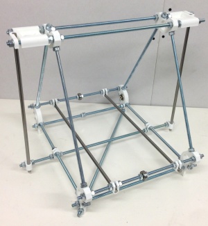
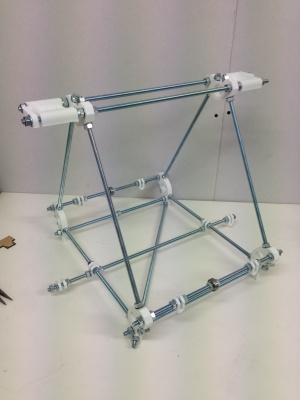
By the end of this stage, your machine should look like this:

Tools
You will need the following tools
- M8 (13mm) spanner
- Adjustable spanner
- 300mm Rule
- Lasercut MDF Measuring template (supplied with kit)
- (optional) Spirit level, cotton and Blu-tack
Frame triangles
 |
|
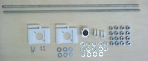
| Item | Quantity |
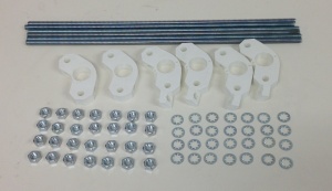
| 370mm M8 rods | 6 |
| Printed frame vertex with foot | 4 |
| Printed frame vertex | 2 |
| Printed frame clips | 2 |
| M8 nuts | 28 |
| M8 lock washers | 28 |
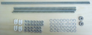
Note that there are three types of printed U clips in your kit:
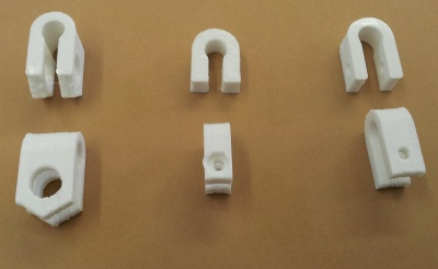
The ones on the left are the frame clips, the ones in the middle are the Z-drive flexible coupling clips, and the ones on the right are the printed-circuit-board clips. For this step you want the ones on the left.
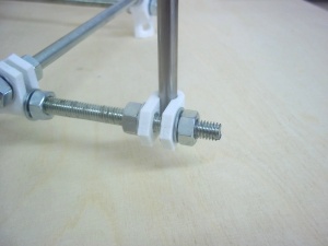
Split the components into two equal sets. The footed frame vertices are not all the same; there are two pairs. For each frame triangle, use a pair of vertices with feet that point in different directions as shown below.

Also, make sure you slide a frame clip along the bottom M8 threaded bars between the frame vertices with feet, with a lock washer and nut either side. The other nuts should also all have lock washers under them. Loosely screw together each frame triangle.
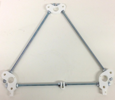
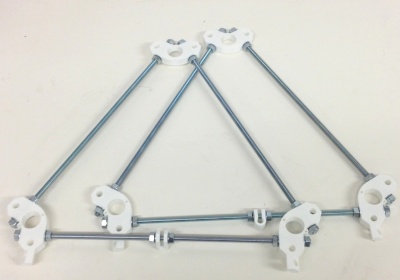
Make the gap between the frame vertices measured face to face next to where the nuts and washers tighten about 290 mm.

Your kit has a template to make it easy to get these measurements right.
Don’t tighten anything at this stage.
Cross bars
 |
|
| Item | Quantity |
| 330mm M8 rods | 4 |
| 470mm M8 rods | 2 |
| Printed frame clips | 4 |
| 8mm bearings | 2 |
| M8 lock washers | 24 |
| M8 nuts | 26 |
Assemble the bars as shown in the following picture:
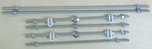
NOTE: the 3rd and 5th bars (the ones with 608 bearings) are not quite the same! One does not have washers around the bearing.
From top to bottom and left to right the sequences are:
- Lock washer, nut, nut, lock washer
- Lock washer, nut, nut, lock washer
- Lock washer, nut, nut, lock washer, frame clip, lock washer, nut, nut, lock washer, bearing, lock washer, nut, nut lock washer, frame clip, lock washer, nut, nut, lock washer
- Lock washer, nut, nut, lock washer, lock washer,nut, nut, lock washer
- Lock washer, nut, nut, lock washer, frame clip, lock washer, nut, nut, bearing, nut, nut, lock washer, frame clip, lock washer, nut, nut, lock washer
- Lock washer, nut, nut, lock washer.
Put them all together
| Item | Quantity |
| M8 nuts | 12 |
| M8 lock washers | 12 |
Slide all the cross bars into one of the triangles as shown below, and secure lightly with a locking washer and nut on each rod end. Next slide the second triangle onto the other end of the cross bars; use a locking washer and a nut on each rod end. The holes in the feet should line up to form an X as shown in red below.

Using the numbers of the rods from Step 2:
At the top attach the two long Rods: 1 and 2.
Back top: Rod 3
Back bottom: Rod 4
Front top: Rod 5
Front bottom: Rod 6
Now go round the frame tightening everything up using two spanners. Tighten the triangles first, then the six bars in the x direction.
Use the template to get the measurements right.
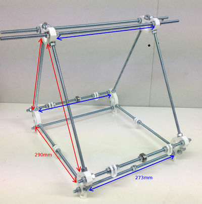
Make the gap between the faces of the vertices on the triangles 290mm, as mentioned above. Make the gap in the x direction between the faces of the vertices 273mm, along the length of each crossbar.
Get the two top rods even, with an equal amount projecting each side, then move the back one 5mm to the right and the front one 5mm to the left.
Try to get the measurements accurate. But it is more important to get the lengths equal than to get them precise.
Z-motor mounts, diagonal, and power connector
 |
|
| Item | Quantity |
| 470mm M8 rods | 2 |
| Printed Z motor holders | 2 |
| Printed frame clips | 2 |
| M8 nuts | 16 |
| M8 lock washers | 14 |
| M8 washers | 10 |
| XLR panel plug | 1 |
| 20mm M3 caps | 2 |
| M3 washers | 2 |
| M3 nuts | 2 |
Put the two frame clips on the bottom rods of the frame triangles roughly in the middle of their bars. Using a 470mm rod, thread it through the two frame clips, with a nut and lock washer each side. You may have to twist the rod to get it through the frame clips, using its thread to move it – it can be quite a snug fit. Secure the rod to the frame with another lock washer and nut on the outside of each frame clip.
Use nuts and lock washers to put two more frame clips on its ends for the Z smooth rods, as shown below. Leave all these loose.
The order of parts on the lower rod should be:
nut, lock washer, frame clip (for z smooth rod), lock washer, nut, nut, lock washer, frame clip (frame), lock washer, nut – (gap between frame triangles) – nut, lock washer, frame clip (frame), lock washer, nut, nut, lock washer, frame clip (for z smooth rod), lock washer, nut
Next thread the base diagonal rod through two of the four feet. Put nuts and lock washers on it both inside and outside each foot, but leave them lose.
Put eight smooth washers on the top bars, with two on either side of each rod then put the Z motor mounts on.
Secure them with two nuts each, with one smooth washer and one lock washer. The smooth washer goes on the clamp that will hold the Z rods. Tighten the other nuts against their lock washers, but leave the Z-rod-clamp nuts lose.
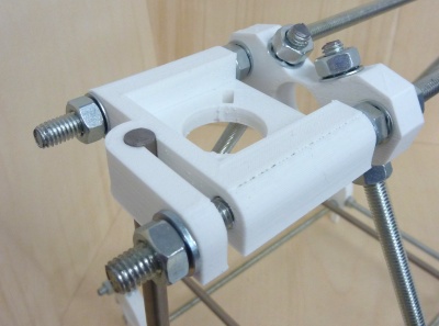
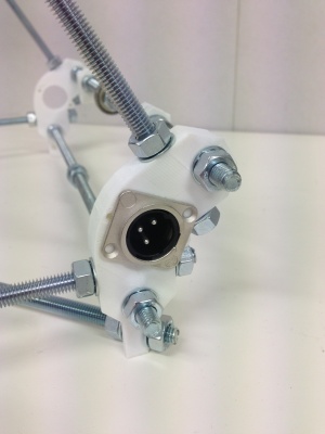
Fit the XLR plug to the frame vertex at the rear right of the machine with the socked facing outwards, i.e. this is the side with the nuts on the bottom bar and on the foot with the diagonal cross brace, using the M3 screws, nuts and washers. The washers go under the nuts. Fit the plug so that the triangle formed by its three pins points upwards.
Smooth rods
 |
|
| Item | Quantity |
| 400mm smooth rods (Y) | 2 |
| 350mm smooth rods (Z) | 2 |
If the ends of the rods are sharp or burred from cutting, use a file to smooth off the ends to give a small taper/bevel/chamfer; 1mm is fine. Without it, there is a risk of unseating the balls inside linear bearings while inserting the rods.
Check that the linear bearings slide smoothly on each of the smooth rods. The linear bearings may need a little extra oil, and the smooth rod may need cleaning, for smooth running. The quick way to clean the smooth rod is to put it in an electric drill, then use wire wool or a kitchen scourer on it while the drill turns the rod. Be careful though!
Slide the Y rods through the frame clips. Adjust the frame clips on the left-hand Y rod so that there is a gap of 22mm between their nuts and the nuts on the left frame triangle. Adjust the right-hand Y rod frame clips so there is 175mm between the rods. Lightly tighten the clamps on the rods.
Now slide the two Z smooth rods into place. Do not over-tighten the clamping nuts on the Z motor mounts. The rods need to be held firm, that is all.
Aligning the frame
Place the frame on a flat surface. Wooden furniture, by and large, is not flat. But thick kitchen worktops are very flat.
Frame alignment order:
1. Check all triangle sides are equal
2. Check cross bars (between vertices of triangles) are all equal
3. Adjust base diagonal to square the base; you should be able to measure across the corners of the base (upside down is easiest) – the red lines shown in the image here:

4. If the frame doesn’t sit flat on the table (assuming a flat table) once you’ve done this, press the frame on the corners that are high, so the base square does sit flat.
5. Use the supplied glass to check that the Y axis smooth rods are level with each other. The rods need to be level, or the heated bed will not move in one plane only; one side will rise and fall as it move back and forth on the Y axis. Place the glass on the rods, and see if the glass rocks. Use a piece of paper on each side, and at each end, to check there is no gap between rod and glass. If the rods are not level, check your table is flat, that nothing is caught under the footed vertices, and that the smooth rod bar clamps are evenly clamped. You will have to remove the rods to fit the Y axis and bed, but this test will check that your construction is correct and the frame is square. If you can’t get the rods quite level, you may need to place a shim under one foot, like a folded piece of paper, to get the bed perfectly level. Leave doing this until later.
6. Square the Z rods front/back. Tie a piece of string quite tightly around the base of both Z rods, and measure along the triangle bottom rod on each side to get the rods central. Equalise the length by moving the frame clip along the triangle bottom rod.

7. Square the Z rods left/right, using a set square. (you can put the glass on the Y rods diagonally to help)

8. Measure the distance between the Z rods top and bottom to check they are parallel
You can now tighten the M8 nuts along the bottom cross bar. You will have to remove the Z rods to fit the X axis; only undo the outer nut on each side, you should then be able to put them back in without moving the frame too much, though you may need to check it again after fitting the X axis.
You can revisit this checklist at any point during building and running your machine, to check your frame is still square.
Frame finished
You will now have an assembled RepRapPro Mendel frame (though the smooth Y rods and the bearings will still be loose):