
Contents
Goal
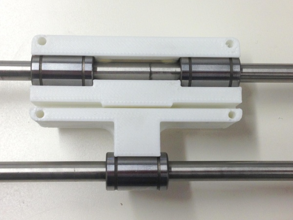
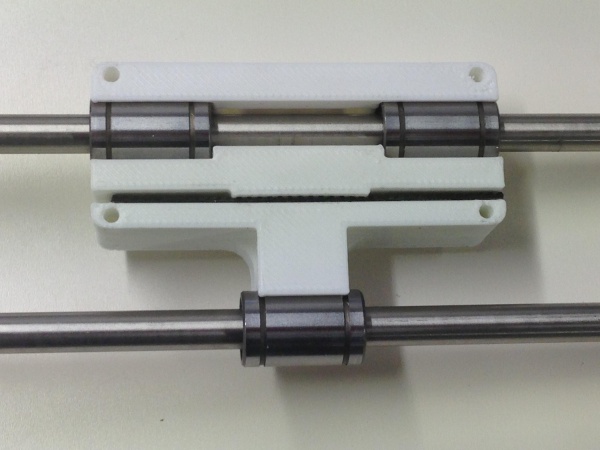
By the end of this stage, your X-axis should look like this:
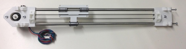
The drive belt will be fitted later, when the X axis is attached to the printer. Also, the picture doesn’t show Z endstop adjuster, but it should.
Tools
You will need the following tools
- M3 Allen key
- Long-nosed pliers
- Tweezers
X ends assembly
|
 |
Begin by assembling the X Idler Bracket. Take one M3x20 cap screw and a corresponding washer and insert it through the hole in the centre of the part as shown below. Then insert this assembly through the 623 idler bearing, through the cover and secure with a M3 nut and washer:
Next insert two M3 nuts into the slots on the back of the idler bracket. These are intentionally a tight fit, so you may need to use a long-nosed pliers in order to grip them. The nuts should go in sufficiently far that the holes of the M3 nuts line up with the small holes in the end of the idler bracket. Insert 2 M3x25 cap screws through each of these two holes, and into the nut.
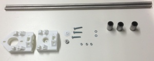
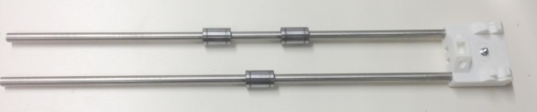
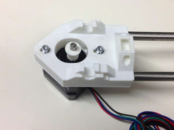
Next begin to assemble the axis. Take the 428mm smooth rods and insert these into the large holes in the end of the X idler bracket. Then proceed to slide the linear bearings onto the smooth rods. Note the orientation of the bearings, when looking at the top/complex side of the idler bracket, two bearings go on the top bar with the one remaining bearing on the bottom bar as shown:
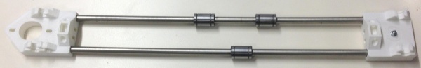
Ensure the rods are completely inserted into the X idler bracket, then insert the free end of the rods into the X motor bracket:
X Motor assembly
|
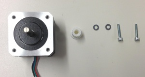 |
Take an MXL pulley and push it onto the motor shaft, taking care to note its orientation.

If you were supplied with aluminium pulleys (kits since Decemeber 2013), the pulley has a threaded hole in it for a grub screw to hold it on the motor shaft. Install the pulley with the pulley teeth closest to the motor body. The motor shaft has a flat on it; align the grub screw with this, and tighten the grub screw using a 1.5mm Allen key.
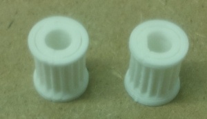
If you were supplied with printed plastic pulleys, the bore of the pulley is D shaped to match the motor shaft. One end of the pulley bore is round to make it easier to slide it onto the motor shaft. The pulley should therefore be pushed onto the motor shaft, round end first. It should be a tight fit, and you may have to tap it into place. Use a soft hammer, or a wood block. If you place a tube against the pulley that will fit over the motor shaft, you can tap the end of the tube to place the pulley. Support the motor shaft, not the motor body, from the other end as you tap. You can secure it with a drop of superglue if you like (make sure the shaft is completely free of grease). Take care that no glue gets near the shaft’s entry to the motor.
Leave a gap of about a millimetre between the pulley and the motor body, so the pulley can turn freely, and not rub against the motor body.
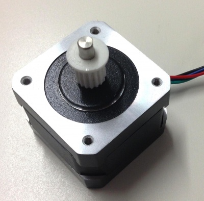
Note: picture shows a pulley with one flange; this has been updated with a 2-flange pulley.
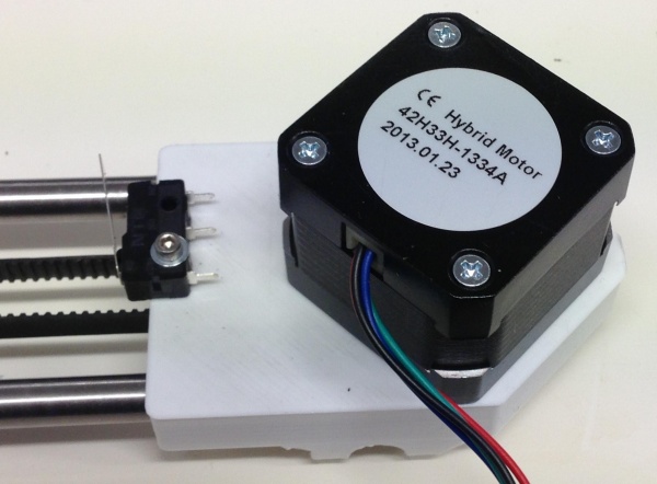
Use the two M3 cap screws and corresponding washers to secure the motor to the X motor bracket as shown below. Note the orientation of the motor wire relative to the bracket.
Z Endstop Adjuster
|
 |
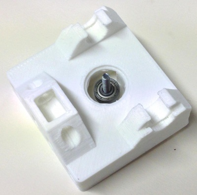
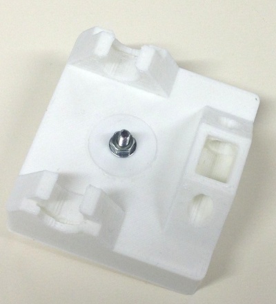
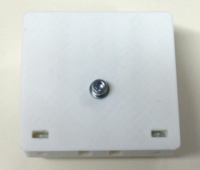
In this step we assemble a Z endstop adjuster. This is used to ensure that the extruder nozzle is just the right height above the bed. Take the M3 cap screw and a washer and insert them into the spring with a washer on the opposite site. This assembly inserts into the small hole on the X motor mount by the bottom clip bearing holder. Place the nut into the nut trap on the opposite side of the hole and tighten to take up the slack as shown below:

The picture above shows the X motor end with bushings, Z leadscrew nut and spring; these are added at a later stage.
X carriage assembly
|
 |
Firstly push the linear bearings on the X axis into their slots on the X carriage. THE BEARINGS SHOULD ONLY BE PUSHED IN FROM THE SIDES, PUSHING THEM IN FROM THE FRONT WILL RESULT IN THE X CARRIAGE SNAPPING. The bearing should be a snug fit. But if they are a little lose, simply wrap a layer or two of Kapton tape round them (take care not to get bubbles under it or creases in it).
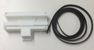
Cut off a small length of belt approximately 80mm long (the width of the X carriage), and press this into the slot of the carriage with the teeth facing upwards. This fit is deliberately tight and you may need to use a small flat head screw driver to push the belt into the slot. The belt should be pushed to the very back of the slot.
The remaining belt is fitted after the axis has been mounted on the machine, so you don’t cut it too short now.
X Endstop
|
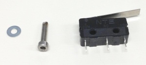 |
Insert the M2.5 capscrew and washer into the hole nearest the button of the microswitch with the lever facing upwards. This then screws directly into the small back of the X motor bracket next to the motor as shown below:
Your X axis is now complete and you can move on to the next stage.