
Contents
Multimaterial master/slave communication problems
Check they are set up correctly
1. Update both the master and slave firmware to the latest version available. Check the version your firmware is using by connecting to the master via Pronterface, then press the reset button on the master Melzi. The log window in Pronterface will show the startup info:
start
echo:Marlin 1.0.8 RRP
echo: Last Updated: 2014-06-02 | Author: RepRapPro - AB
echo: Free Memory: 10882  PlannerBufferBytes: 1232
(v1.0.8, 2014-06-02 is the latest master firmware version as of 2014/09/04)
Make sure you disconnect the comms cable while you update, reconnect it afterwards. The firmware is changing all the time, which improvements and bug fixes. SEE GUIDE HERE.
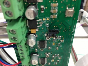
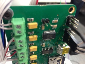
2. Make sure that the central jumper on BOTH boards (master AND slave) are on the two pins closest to the screw terminals (ie both on mains power); the slave won’t connect to the master without it.
3. Generally, it’s easiest to connect if both the master and slave have the autoreset jumper removed. Replace it only while uploading firmware.
4. If no LED comes on, either there is no power, or the hot end thermistor on the master is not being read correctly. This means you won’t be able to connect to the master, either!
5. If the LED is on constant after switching on, on either master or slave, the thermistors are not being read correctly.
6. You can check the slave is functioning correctly by connecting directly. Disconnect the comms cable, connect via USB to slave, connect via pronterface. When it says “Connecting…”, press the reset button on the slave, and you should get the message:
RepRapPro slave controller Version 1.2, 2014-06-02 restarted.
 Temps:22.37 23.46
(v1.2, 2014-06-02 is the latest slave firmware version as of 2014/09/04)
If you get something like:
RepRapPro slave controller Version 1.2, 2014-06-02 restarted.
 Temps:-273.15 23.46
ERROR: temp bounds exceeded
after this, your thermistors are not reading correctly. Check your wiring, particularly the thermistor wires. The temperature reported will indicate which thermistor is not reporting correctly; the first temperature is T1, the second T2. If the board doesn’t report temperatures, you need to update the firmware on your Slave. SEE GUIDE HERE.
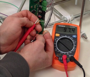
7. If you’re having problems with your thermistor readings, check your hot end thermistors by removing them from the screw terminals, and measure the resistance of the wires. Each thermistor should have a reading of around 100k ohms. If it isn’t, check your thermistor wiring.
8. When you connect to the master, with the slave attached via the comms cable, press the reset button on the master Melzi so you can see the first messages that the master displays (check that BOTH boards reset – the LED on both boards should turn off for 10 seconds). If it says:
Slave init. Please wait ...
Slave error (s); comms error will cause heater errors: Dud heater 1, [or 2, or both]
either there is a communication problem, or there is a thermistor problem.
If it says:
Slave init. Please wait ...
.Slave ready
The communications are okay. However, you may still have strange temperature readings. Check the M503 output. If you have:
echo:   M301 H1 P12.00 I0.27 D655.74 W125.00
   M301 H2 P-273.00 I-273.00 D-273.00 W-273.00
   M301 H3 P-273.00 I-273.00 D-273.00 W-273.00
… and …
 Bed/extruder 0 beta: 4126.00 resistor: 4700.00 thermistor: 9999.99 inf: 0.01
 Bed/extruder 1 beta: 3960.00 resistor: 4700.00 thermistor: 99999.92 inf: 0.17
 Bed/extruder 2 beta: -273.00 resistor: -273.00 thermistor: -109.27 inf: -273.00
 Bed/extruder 3 beta: -273.00 resistor: -273.00 thermistor: -109.27 inf: -273.00
Run the reset gcode (see section below) appropriate to your machine and check the output matches the examples below.
Checking PID and thermistor settings
Check that the M503 output has the PID and thermistor settings showing correctly. They should look like:
echo:   M301 H1 P12.00 I0.27 D655.74 W125.00
   M301 H2 P12.00 I0.27 D655.74 W125.00
   M301 H3 P12.00 I0.27 D655.74 W125.00
and..
 Bed/extruder 0 beta: 4126.00 resistor: 4700.00 thermistor: 9999.99 inf: 0.01
 Bed/extruder 1 beta: 3960.00 resistor: 4700.00 thermistor: 99999.92 inf: 0.17
 Bed/extruder 2 beta: 3960.00 resistor: 4700.00 thermistor: 99999.92 inf: 0.17
 Bed/extruder 3 beta: 3960.00 resistor: 4700.00 thermistor: 99999.92 inf: 0.17
For PID, all three should match. For thermistor settings, Bed/extruder 1, 2 and 3 should match. These may not be your exact settings, but show roughly what it should look like. Sometimes, the response can be garbled, with extraneous numbers showing up in these two settings, eg:
 Bed/extruder 1 beta: 3960.00 resistor: 4700.00 thermistor: 100000.00 inf: 0.17
 Bed/extruder 2 beta: 3960.00 resistor: 4700.00 thermistor: 99702.65 inf: 0.17
 Bed/extruder 3 beta: 255.00 resistor: 3960.00 thermistor: 11054.49 inf: 4700.00
The first and second are correct, but the third has an extraneous number for the beta value; 255. And the resistor value should be 4700, but has been set to the beta value. This is due to garbled communication between the master and slave. It can also effect the PID settings, which controls how much power is applied to the heater. The hot end may report the wrong temperature, or the wrong settings have been used to control the heater. Any of these can cause the Slave Melzi to be unresponsive.
A number of factors can cause the garbled communication:
Firmware. Check yours is up to date. The last update to the firmware was back in June last year, where we modified the code to improve the communication between the master and slave. As you bought your Tricolour in November 2014, you should have the latest firmware already. Check by following the first instructions here: https://reprapltd.com/reprappro/documentation/mendel-tricolour/troubleshooting/#Multimaterial_masterslave_communication_problems. You can also check that the master and slave are correctly setup by following the rest of this section.
Pronterface ‘Watch’. As it says in the instructions here: https://reprapltd.com/reprappro/documentation/mendel-tricolour/multimaterials/#Test_that_everything_is_working
“Run Pronterface and connect it to your RepRap. MAKE SURE YOU TURN OFF ‘WATCH’, WHICH AUTO-UPDATES THE TEMPERATURE! This interferes with the communications between the master and slave, and will cause the PID and theremistor settings to be set incorrectly.” This needs to be switched off whenever the master and slave are setting up communication, ie when you press reset, or when you send M503. Also leave it turned off if you are printing directly from USB (ie not from the SD card), or you will get errors. The rest of the time it can be switched on.
Stored settings. Each time you reset the printer, or send M503 to the printer, the master polls the slave to get it’s settings. However, if you have stored settings (M500) that are incorrect, it will use these. The only way around this is to reset the master to factory defaults. Before you do, send an M503 command, and copy your settings from the log window (if you have changed them from standard) into a text document. Then do the following sequence:
- Set power jumper on both boards to mains power (not USB)
- Disconnect master/slave cable (IMPORTANT)
- Press reset button on master
- Connect to master via Pronterface
- Send ‘M502’
- Send ‘M500’
- Press reset button on master
- Reconnect master/slave cable
- Press reset button on master
- Check temperature, see if nozzles 1 and 2 have the correct values for PID and thermistor. Test motors.
Repeat all the above if it doesn’t work first time; for some reason it sometimes needs to be done twice! This should reset the EEPROM values on the master to default. You can set any special settings you have from the text document you created.
Master/slave communication cable. It’s possible that the master/slave communication cable is causing problems. The master and slave sync together using the ‘CLK’ output on the master, which controls the slave. If there is extra resistance on this wire (ie if the cable is damaged, or no made well), this can cause the two boards not to sync together. Remake the cable if you continue to have problems.
Reset Firmware Settings
If you are having communication errors, or your Melzi/Slave is not operating in a way that you’d expect, first check all of your electrical connections using the guide above.
Ensure you are running the latest version of our firmware for both the Master and the Slave board. Firmware upgrade instructions are here. Please get in touch with RepRapPro support if you have any issues with this step.
Once this is done, you will find Gcode files in the Marlin folder here. There are a number of versions, depending on the date your Tricolour kit was delivered. Connect the USB cable to your master board as if you were going to print, open pronterface, load the correct Gcode for your machine and press ‘PRINT’. You will see several messages appear in the pronterface log window as each setting is updated in turn. Finally they are stored and a command is sent to display all of the current settings in pronterface. Following this, press the reset button on the master Melzi board. The board will reset, display the current firmware version, and try to connect to the slave. Please check that your settings are similar to those found below:
For current Tricolour (shipping after 29/5/2014)
echo:Steps per unit:
echo: M92 X87.489 Y87.489 Z4000.00 E660.00
echo:Maximum feedrates (mm/s):
echo: M203 X500.00 Y500.00 Z5.00 E45.00
echo:Maximum Acceleration (mm/s2):
echo: M201 X1000 Y1000 Z50 E250
echo:Acceleration: S=acceleration, T=retract acceleration
echo: M204 S1000.00 T1000.00
echo:Advanced variables: S=Min feedrate (mm/s), T=Min travel feedrate (mm/s), B=minimum segment time (ms), X=maximum xY jerk (mm/s), Z=maximum Z jerk (mm/s)
echo: M205 S0.00 T0.00 B20000 X15.00 Z0.40 E15.00
echo: M206 X0.00 Y0.00 Z0.00
echo:PID settings:
echo: M301 H1 P12.00 I2.20 D80.00 W125.00
M301 H2 P12.00 I2.20 D80.00 W125.00
M301 H3 P12.00 I2.20 D80.00 W125.00
FPU Enabled no
Axis 0 max: 210.00 Axis 1 max: 210.00 Axis 2 max: 140.00
Bed/extruder 0 beta: 3988.00 resistor: 4700.00 thermistor: 9999.99 inf: 0.01
Bed/extruder 1 beta: 4138.00 resistor: 4700.00 thermistor: 99999.92 inf: 0.17
Bed/extruder 2 beta: 4138.00 resistor: 4700.00 thermistor: 99702.65 inf: 0.17
Bed/extruder 3 beta: 4138.00 resistor: 4700.00 thermistor: 99702.65 inf: 0.17
Extruder: 0 dX: 0.00 dY: 0.00 dZ: 0.00 standby temp: 150.00 operating temp: 200.00
Extruder: 1 dX: -42.00 dY: 0.00 dZ: 0.00 standby temp: 150.00 operating temp: 200.00
Extruder: 2 dX: -42.00 dY: -32.00 dZ: 0.00 standby temp: 150.00 operating temp: 200.00
For the Legacy Mendel with Colour Upgrade
echo:Steps per unit:
echo: M92 X91.43 Y91.43 Z4000.00 E660.00
echo:Maximum feedrates (mm/s):
echo: M203 X500.00 Y500.00 Z5.00 E45.00
echo:Maximum Acceleration (mm/s2):
echo: M201 X1000 Y1000 Z50 E250
echo:Acceleration: S=acceleration, T=retract acceleration
echo: M204 S1000.00 T1000.00
echo:Advanced variables: S=Min feedrate (mm/s), T=Min travel feedrate (mm/s), B=minimum segment time (ms), X=maximum xY jerk (mm/s), Z=maximum Z jerk (mm/s)
echo: M205 S0.00 T0.00 B20000 X15.00 Z0.40 E15.00
echo: M206 X0.00 Y0.00 Z0.00
echo:PID settings:
echo: M301 H1 P12.00 I2.20 D80.00 W125.00
M301 H2 P12.00 I2.20 D80.00 W125.00
M301 H3 P12.00 I2.20 D80.00 W125.00
FPU Enabled no
Axis 0 max: 210.00 Axis 1 max: 210.00 Axis 2 max: 140.00
Bed/extruder 0 beta: 3480.00 resistor: 4700.00 thermistor: 9999.99 inf: 0.09
Bed/extruder 1 beta: 3960.00 resistor: 4700.00 thermistor: 99999.92 inf: 0.17
Bed/extruder 2 beta: 3960.00 resistor: 4700.00 thermistor: 99702.65 inf: 0.17
Bed/extruder 3 beta: 3960.00 resistor: 4700.00 thermistor: 99702.65 inf: 0.17
Extruder: 0 dX: 0.00 dY: 0.00 dZ: 0.00 standby temp: 150.00 operating temp: 200.00
Extruder: 1 dX: -34.00 dY: 4.00 dZ: 0.00 standby temp: 150.00 operating temp: 200.00
Extruder: 2 dX: -11.00 dY: 51.00 dZ: 0.00 standby temp: 150.00 operating temp: 200.00
Basic Melzi connection problems
Problem
- Can’t connect to Melzi
- No LED lights up on Melzi
- Melzi disconnects randomly
Solution
Check Melzi first:
- Connecting using USB power. Turn mains power off, move the central power jumper to the pins furthest from the screw terminals, plug in USB lead. The position of the autoreset jumper shouldn’t matter, though generally best to leave it off. Press the reset button on the board to check it hasn’t got stuck down. Check that the pin furthest from the screw terminals on the power jumper is supplying 5V – if not, you may have a damaged USB lead. Does the LED light on the board start flashing after 20 seconds or so? If not, it’s possible the firmware or the Arduino processor itself that’s damaged.
- In normal running, the autoreset jumper (the one at the top of the board) should be removed, or left hanging on just one of the pins, and the central power jumper should be bridging the middle pin and the pin closest to the screw terminals. This means the Arduino processor is supplied with power from the 12V power input, rather than USB.
- If the hot end fan comes on, the board is getting some power. Check that you get 12V at the power input screw terminals, that the polarity is correct (though various things will blow up if the polarity is wrong!), and that the wires are in good contact with the screw terminals, ie can’t be pulled out, or feel loose when you wiggle them. Then check that the pin closest to the screw terminals on the power jumper is supplying 5V. If you don’t get 5V on this pin, the voltage regulator that supplies the logic side of the board (processor, endstops, thermistors) with 5V is not working.
- If you are getting 5V on this pin, but the LED on the board doesn’t come on (can take up to 20 seconds), then something has happened to the firmware on the Arduino processor, or a short circuit has caused damage to the processor itself. Press the reset button on the board to check it hasn’t got stuck down.
Check PC software installation:
- Have you installed the USB driver? See: RepRapPro_Tricolour_commissioning#USB_Driver
- If you used the pre-compiled version of Pronterface, check you have selected the correct port and baud rate
- If you have installed from source, check you installed all the correct parts: https://github.com/reprappro/Software/blob/master/README.md#installing-dependencies
- If your OS is Windows 7, you may have to do this fix: RepRapPro_Tricolour_commissioning#Windows_7
USB driver problems:
If, when you plug your Melzi in, it is recognised as an ‘FT232R USB UART’ in ‘other devices’ in the Device Manager, you need to manually install the FTDI driver:
- Download the driver from www.ftdichip.com and unzip/expand the folder in a sensible place on your hard drive.
- Right-click on ‘FT232R USB UART’ in the Device Manager, select ‘Properties’, select ‘Driver’ tab, select ‘Update Driver…’
- Select ‘Browse my computer for driver software’ then ‘Let me pick from a list of device drivers on my computer’
- Select ‘Have Disk…’ then navigate to the folder containing the files you extracted in step 1
- Select the ‘ftdibus.inf’, and click ‘Open’, then ‘OK’, then ‘Next’. You may get a warning about digitally signing the driver; proceed anyway.
- The Melzi should now be recognised in ‘other devices’ as a ‘USB Serial Port’. Select it again, and repeat the installation process above, this time selecting the ‘ftdiport.inf’ driver.
- Once installed correctly, the Melzi should show up under ‘Ports (COM & LPT)’ as ‘USB Serial Port (COM[x])’, where [x] is the assigned COM port.
- There are two parts to the driver; the second is listed under ‘Universal Serial Bus controllers’ in the Device Manager, called ‘USB Serial Converter’. You can check the driver that is installed correctly, by going to the Properties > Driver tab, and see that it’s the same version as the ‘USB Serial Port’.
- You should now be able to connect with Pronterface.
There is a video which show you how to do this on youtube, too: www.youtube.com
Random disconnections:
These can have a variety of causes. USB is quite prone to Electro Magnetic Interference (EMI), via the power line. Large motors (in air conditioning, fridges, fans, drills and other hand tools etc) starting and stopping on the same ring main can cause power spikes, while other high current devices, unstable mains supply, or poor USB power connectivity on the host PC can knock out the USB connection. If the printer seems to continue working without resetting (for example, if you are printing from SD card, it continues to print), this is the most likely source of the problem. Check that the USB cable is connected properly, and for any damage – a poor connection will be more susceptible. Customers have found that adding a surge suppressors, power conditioners and/or UPSs to smooth the mains supply, and/or using a USB cable with a ferrite core, can help.
If the printer is resetting, the cause is more likely to be related to power to the printer. Double-check that the 12V power input wires and the heated bed power wires are well-seated in the screw terminals; they should be really solid. They have to carry a lot of current, and a loose connection here will generate heat, and possibly cause a disconnection/reset if the contact is poor. Once you are satisfied with this, check that you are getting 12V from the power supply when under load. Test at the 12V power input screw terminals, turn on the bed, and see if the voltage drops. We occasionally have PSUs that give uneven voltage.
When these disconnections happen, Pronterface keeps the connection to the port open. The Melzi is still there, but reconnects with a different port number. Usually in Pronterface, you can click ‘Disconnect’ (to close the connection to the printer), then click the ‘Port’ button; the new USB port will be selected, to which you can then connect.
Poor or no extrusion
Problem
This could be due to a number of reasons:
- Initial construction problems (if the nozzle has never successfully extruded)
- The nozzle is partially or fully blocked
- Extruder motor does not move much but makes a squeaking noise.
- Extruder motor rotates, but the gears do not.
- Extruder drive motor and gears rotate, but the filament does not feed.
- Bowden tube has popped out of the pneumatic fitting or brass union.
- The extruder gears squeak, rub and/or get stuck as the big gear turns.
Solutions
1. Construction problems
- Check that the hot end fan is on ALL THE TIME. If the hot end fan turns off, heat can travel higher up the nozzle, and the force of extrusion increases, eventually stopping extrusion. The hot end fan MUST run all the time (it should be wired to the +12V (for Mendel) or +19V (for Huxley) directly), and there should be good contact of the heatsink to the heatsink block. Make sure the heatsink is installed so that the fan can blow air through it!
- Check that the brass tapered nut is tight. Tighten the brass tapered nut and heater block together tightly with spanners (more than finger tight!); this will ensure the threads make good contact with the nozzle, and heat transfers well.
- If the ptfe nozzle liner is not cut square, or cut too short, and there is sufficient gap that fills with molten filament, again the force of extrusion increases. Cut a new piece of ptfe tube, 8mm long, with square ends.
- If the Bowden tube is tight into the brass unions, and the filament has difficulty moving through the tube, this increases the force needed for extrusion. The tube should be 10mm into the brass unions, then run a 2mm drill into the ends to clear them. Push a piece of filament through to check it is smooth, and to clear out any debris.
- If the teeth of the hobbed insert has slipped on the filament, there may be pieces of plastic in the teeth, which the filament will slip on. Remove the filament, take out the big gear with the hobbed insert, then check and clean the teeth of the hobbed insert – a small wire brush is good for this.
- Check the hobbed insert has not loosened on the M3 hex bolt. Use superglue or loctite to keep it in position.
2. Nozzle blockage
To ensure the nozzle and melt zone are free from contamination, follow these steps:
(i) Heat nozzle to around the extrusion temperature (PLA = 200C) and feed (by hand, turning the large gear) some filament into the nozzle.
(ii) Set the nozzle temperature to around 80C and wait for the temperature to settle there.
(iii) Reverse the extruder (by hand, or send M302 command to override ‘cold extrusion prevented’ message), pulling out the filament from the melt chamber, along with any contamination.
(iv) Cut the contaminated end from the filament, and reinsert. Heat nozzle to extrude temperature, test extrusion. Repeat if necessary.
(v) Only in the worst case will you need to disassemble and clean the hot end.
3. All extruders
If the extruder motor does not move as expected, but makes a squeaking noise or just vibrates, it may mean it does not have enough torque to drive the extruder feed mechanism.
- Check that the nozzle is not blocked (see solution 2)
- Check that the idler bearing can rotate, and that the clamp bolts that tension the idler bearing onto the filament are not overtightened
- Check the diameter of your filament is not too wide (over 2mm in diameter will not feed through the extruder)
- Ensure Vref on the stepper driver is set to 0.6v, as described in the Tricolour commissioning instructions.
Old-style extruder (Huxley, Legacy Mendel)
4. If the gears are not rotating with the motor, tighten the M3x10mm socket set screw which anchors the small gear to the motor shaft.
5. This could be due to a number of reasons.
- The teeth of the hobbed bolt have plastic in them. This will cause the teeth to slip on the filament. Clean the teeth with a pointy tool.
- It is possible for the M6 lock nut to come a little loose after much printing, allowing for some play in the hobbed stud. This can result in the filament wandering from the hobbed section of the stud during a print. Once the filament is on the smooth part of the stud, it will no longer feed.
- If the filament is still over the hobb, and has stopped feeding, there is most likely a section worn away from the side of the filament. This could be due to a nozzle jam. To resolve this, follow the instructions as per solution 2 above. Clean any debris from the teeth of the hobbed bolt.
6. This is usually due to a nozzle jam. To resolve this, follow the instructions as per solution 2 above. Reconnect the Bowden tube and test.
7. The motor is adjusted too tightly onto the big gear. Undo the motor mounting screws, adjust.
New-style extruder (Huxley, Mono Mendel, Tricolour Mendel)
4. It is unlikely the small gear will rotate on the motor shaft. If it does, contact RepRapPro support for a replacement. On the big gear, check that the hex head bolt is not rotating in the hex hole. If it is, again, you will need a replacement. As a temporary fix, you may be able to use epoxy glue or superglue to get the hex head to hold again.
5. There are a number of potential reasons for this:
- The hobbed insert is not superglued/loctited onto the M3 bolt. It will eventually loosen. Particularly noticeable on retractions.
- The teeth of the hobbed insert have plastic in them. This will cause the teeth to slip on the filament. Clean the teeth with a pointy tool.
- The two bolt that tension the idler bearing onto the hobbed insert may be too loose, or too tight. Usually, the gap at the top of the extruder block should be just closed. Adjust tension on these bolts and test.
- The filament may be to thin, or it is trying to grip on a section where filament has been worn away. Remove filament and check diameter.
6. If the ptfe tube pushes out of the brass union, it is probably not screwed in far enough into the union. It should have about 10mm of thread. Remember to drill, with a 2mm drill, into the brass union with the ptfe in place, or there may be a tight spot that the filament can’t push past.
7. There are a number of potential reasons for this:
- Undo the two bolts that hold the motor in place – there is some ‘wiggle’ room that should allow a little adjustment of the gear meshing. Tighten them afterwards!
- If the top of the small gear is touching the big gear spokes as it goes around, you may need an extra M3 washer (you should have spares left over) between the 623 bearing and the hobbed insert. If you have superglued/loctited your hobbed insert on the M3 bolt already, you can put an M3 washer between the insert and the outer 623 bearing.
- The small gear should be pushed on the motor shaft so it is flat with the end of the shaft – if you push it on too far, the motor shaft will stick out and may get caught on the spokes of the big gear.
Filament doesn’t stick or parts warp
Problem
If the first layer does not adhere well enough to the heatbed, there is a chance the component(s) will warp during printing.
Solutions
Bed surface
Some people are lucky, and seem to be able to print directly onto the glass bed (aluminium on Huxley), and the PLA sticks. Most, it seems are not so lucky; for them we provide a roll of Kapton tape. Kapton can be applied to the glass surface in strips – try to keep the air bubbles out, and put the strips as close together as possible. Kapton is durable: we use it in the production of kits, and will last at least a couple of months of 24/7 printing. Usually it peels up before the PLA won’t stick to it.
Blue painter’s tape can also be used. PLA doesn’t stick as strongly to it, and the surface isn’t as flat or durable as Kapton, but it is more widely available, and often in wider widths.
Cleanliness of build surface
The bed surface needs to be completely free of all oil and grease (including finger marks), otherwise your prints won’t stick to it.
Set the heatbed to a temperature of 45C and wait for it to settle there. Clean the surface with nail polish remover (containing acetone, glycerine, and as few other ingredients as possible, and definitely not lanolin or any other oil or grease) using a lint free cloth. Set your heatbed to your print temperature ready for printing.
Other products that also work include pure acetone, isopropyl alcohol, white methylated spirits, and white vinegar. These dissolve oil and grease, which then comes off in the cloth you use. They then evaporate completely leaving a clean dry surface. Don’t use Windex/Windowlene or polish; they often have a non-stick component!
Setting Z zero
At the Z ‘home’ position, where Z=0, the nozzle should be just touching the bed. Follow the instructions laid out in Mendel commissioning
Bed temperature
For PLA, try a setting of 50-60C. If you go too hot, the PLA will stay liquid and can be pulled away from the bed by the cooling of subsequent layers. Too cold, and it won’t stick.
Axis sticking problems
Problem
- Axis doesn’t move smoothly
- Motor stalls when moving (sometimes okay at low speed, doesn’t move far enough at high speed)
Solution
- Make sure rods are clean and linear bearings run smoothly. See: RepRapPro_Tricolour_frame_assembly – Smooth_rods
- Accurate frame alignment, so that smooth rods are parallel, is absolutely fundamental to smooth movement. See RepRapPro_Tricolour_frame_assembly – Aligning_the_frame
- For the Z axis, also check:
- Pay careful attention to the fitting of the bushings in the X ends RepRapPro_Tricolour_z_axis_assembly – Z_Drive.
- Then levelling the X axis RepRapPro_Tricolour_commissioning – Level_the_X_axis.
- The two adjuster screws in the end of the X idler are designed to counteract the force of the belt pulling the x-ends inwards; the x axis should be set up so no horizontal pressure is put on the bushings on the Z axis.
- Check stepper motor voltage is not set too low, by measuring the voltage between the axis trimpot and ground (the SD card cover is good) – it should be 0.6V to 0.8V.
- Check that belt alignment is correct, and the belt is not rubbing unduly on belt guides, washers or anything else.
- Check there is no mechanical obstruction to the movement of the belt, or bearings on the smooth rods.
Wobbly Z walls and non-circular circles
Problem
- Vertical walls are not accurately printed on top of each other
- Variability in layer height causes vertical walls not to be smooth
- Circular objects print out square
Solution
Generally we lump these problems together under the term ‘backlash’ http://en.wikipedia.org/wiki/Backlash_%28engineering%29 . This can happen on any of the axes, or a combination of them.
- Check belts are tight enough
- Check belt clamps are tight – these can soften and the belt loosen, particularly when printing ABS at higher temperatures
- Check pulleys are not loose on stepper motor shafts (X and Y axis) – hold the motor shaft with pliers, then try moving the carriage, while looking at the pulley
- Check that the axes are moving freely: see RepRapPro_Tricolour_troubleshooting – Axis_sticking_problems
- Check extrusion is consistent: see RepRapPro_Tricolour_troubleshooting – Poor_or_no_extrusion
Stepped layers
Problem
Partway through a print, the next layer appears to have slipped by a millimetre or two (or much more) causing a step which should not be there. This can be caused by:
- Print head snags on part of the print, usually the print curling up or lifting off the bed. This can cause the belt to skip on the pulley, or the motor to stall.
- Axis snags on something. For example, the wiring catching/getting in the way of movement. This can cause the belt to skip on the pulley, or the motor to stall.
- Stepper driver overheats and temporarily shuts down.
Solution
Nozzle hitting printed part
- The printer should generally have the power to overcome hitting a part while printing. However, if printed parts are curling up, particularly on overhangs or bridging, reducing the extrusion temperature 5°C at a time will usually help. The addition of a cooling fan on the parts will also help reduce curling – see the improvements page. If the parts are curling up from the first layer, see THIS section above
Belt skipping on pulley
- Check belts are tight enough. The actual tension required comes with experience, but should be at least tight enough to produce a low frequency, just audible ‘twang’ on the longest section of belt. Over-tensioning the belts can also be detrimental, as the motors will have to work harder.
- Check that the belt is running smoothly and in line, and the edge of the belt is not snagging on the motor and idler ends. With the motors off, check the axis moves smoothly – if not, see THIS section above.
- Check all wires, cogs and belts whilst printing and reposition/realign anything impeding the smooth movement on all axes.
Stepper motor stalling This is a result of the motor not having enough torque to move the axis (temporarily, since the print continues at the new position).
- Check that the motors are being supplied with sufficient current to meet the demand, by measuring the voltage between the axis trimpot and ground (the SD card cover is good) – it should be 0.6V to 0.8V. To adjust, see instructions HERE.
- Use secondary cooling fan to cool the electronics if they are getting too hot.
Printing ABS
Problem
ABS doesn’t stick, heated bed doesn’t get up to temperature
Solution
Check the voltage of the power supply, particularly under load. Mendel PSUs should supply around 12V; we have had a few power supplies go out that seem to supply a bit less than this, particularly under load. The PSU does have an adjuster, to the right of the screw terminals; you may be able to turn this up to compensate. Some customers are able to turn theirs up to 13 or 14V, which allows the heated bed to heat up quicker and get to a higher temperature. However, don’t go beyond this, or the heated bed will draw too much current. Huxley PSUs should supply 19V, and are not adjustable. However, they should be easily able to reach 120C+ as standard.
Another problem when printing ABS on a Mendel is that the PLA belt clamps under the bed may soften, and the Y axis belt come loose. Make ABS belt clamps your first print! Find them on github here.
The Mendel heatbed can max out at around 100C, due to the thermal mass of the aluminium and glass. However, this is generally okay for the ABS we have tested. You can increase this to around 110C by covering the bed with an insulator while it heats up. In the past, we’ve used a foil-fronted piece of MDF, which reflected heat back onto the bed, but was held off the surface by the clips, so didn’t heat up. Remove it to start printing; the first layer will then be a bit hotter, so should stick better if it’s being difficult, and the temperature will drop during printing to hold at around 100C.
Another improvement suggested by a customer is to put aluminium/kitchen foil between the heatbed PCB and MDF insulator. This also decreased warm up time. Be VERY careful not to short the main power connections through the silver foil!
ABS shouldn’t need heating to more than 110C anyway, as this is beyond it’s glass transition temperature; it’s like printing PLA onto a bed at 80 degrees – the PLA stays so soft it gets pulled off the bed. ABS generally does this above 110C.
Also, keep draughts to a minimum, and try to keep the area around the printer at a reasonable temperature – above 25C minimum. This should help to prevent the part warping as it prints. You can build a small ‘greenhouse’ to cover the printer, but be careful it doesn’t get so hot (over 45C) that the PLA parts of the printer melt!
It should be noted there are plenty of other problems getting ABS to stick at any temperature, and there are quite a few workarounds; the favourite around here are super strength hold hairspray (it can contain both PVA and acrylic) or making a slurry of some ABS dissolved in Acetone, applied to the bed at 50C, and wait for it to dry before printing. Joseph Prusa shows how he does it here: http://www.flickr.com/photos/prusajr/8283827185/in/photostream (follow the pictures in the ‘Older’ direction). And then some people have no problem with ABS at all! It’s a bit of a dark art, but probably depends on the quality of your ABS filament.
Melzi temperature problems
Problem
- Pronterface is unresponsive after connecting to Melzi
- Pronterface reports the temperature as negative, or doesn’t change, for the heatbed and/or hot end
- MINTEMP error
Error:0
: Extruder switched off. MINTEMP triggered !
Error:Printer stopped due to errors. Fix the error and use M999 to restart!. (Temperature is reset. Set it before restarting)
- MAXTEMP error
Error:Temperature heated bed switched off. MAXTEMP triggered !!
Error:Printer stopped due to errors. Fix the error and use M999 to restart!. (Temperature is reset. Set it before restarting)
Solution
If your hot end temperatures are stuck at a particular temperature, it may simply be a faulty connection. You Melzi may seem unresponsive after you connect to it with Pronterface, but click the ‘Watch’ checkbox and the temperature should update. Press reset to see the whole startup message. The chances are you’ll see the ‘MINTEMP’ or ‘MAXTEMP’ error, or something similar, depending on the version of the firmware your board has.
Some temperatures indicate the fault (looking at the hot end temperature):
- around -40C – No thermistor is connected / break in thermistor connection
- -273C – Short circuit between thermistor wires; check wiring. Could also be hot end heater is wired to thermistor screw terminals.
- around 90C – 10k ohm bed thermistor wired into hot end temperature screw terminals (Mendel)
- 20C – What it should report, around room temperature
To test the hot end temperature sensing (Mendel and Huxley):
- Remove the wires from the ‘etemp’ screw terminal.
- Check the temperature in Pronterface. Is the reported temperature the same?
- Bridge the screw terminal connections with a piece of wire. Is there any change in the reported temperature?
- If you have some resistors, wire them into the etemp terminals and check the temperature reported in Pronterface. A 150k ohm resistor should read around 17C, 100k ohm resistor should read around 25C, a 50k ohm resistor should read around 42C, a 10k ohm resistor should read around 90C, a 1k ohm resistor should report around 184C.
To test the bed temperature sensing (Huxley):
- Remove the wires from the ‘btemp’ screw terminal
- Check the temperature in Pronterface. Is the reported temperature the same?
- Bridge the screw terminal connections with a piece of wire. Is there any change in the reported temperature?
- The temperatures reported when using resistors should be similar to the hot end (see above)
To test the bed temperature sensing (Mendel):
- Remove the wires from the ‘btemp’ screw terminal
- Check the temperature in Pronterface. Is the reported temperature the same?
- Bridge the screw terminal connections with a piece of wire. Is there any change in the reported temperature?
- If you have some resistors, wire them into the btemp terminals and check the temperature reported in Pronterface. A 10k ohm resistor should read around 25C, a 1k ohm resistor should report around 85C.
If your Melzi passes these tests, the problem is with your wiring.
- Check the resistance of wires to the thermistors; for the hot end, it should be 100k ohms, for the heated bed it should be 10k ohms (Mendel) or 100k ohms (Huxley), assuming testing at room temperature.
- Check the wires for breaks or loose connections
- Check the thermistors are not broken, or the wires of the thermistor are not touching
If the temperature of your Melzi doesn’t seem to change (or moves slowly, or exhibits other strange behaviour) no matter what you do, it could be due to a short circuit between the 12V (19V for Huxleys) side of the Melzi (stepper drivers, motors, heaters, fans) and the 5V logic side (Arduino chip, endstops, thermistors, USB, SD card, stepper driver logic). This usually causes damage to the Arduino chip on the Melzi, though this is generally confined to the Analogue to Digital Converters (ADC) of the temperature circuits. But it can cause a complete chip failure, and the Melzi to become completely unresponsive.
If this is the case the board will need to be repaired or replaced. But this can’t happen until the initial fault is rectified; any replacement board will suffer the same fate. There may also be other damaged parts, some which may have caused the problem.
The main place this happens is around the hot end, because that’s where the wires (12V/19V hot end heater, 12V/19V hot end fan and 5V hot end thermistor) are in closest proximity; the movement of the x carriage can cause wires to chafe and abrade, connections to bridge, short and/or fail if the wiring has not been connected carefully and neatly enough. Other reasons can be mixing up heater and fan wires with the thermistor wire, or damage to the board by bridging connections by accident. Be aware that 12V/19V runs through the fan and hot end heater constantly when power is applied; they are switched on and off by a MOSFET on the ground side.
Any short will need to be traced and repaired before any fix or replacement of the Melzi, or the same thing will happen to the replacement. The difficulty is that the short may be temporary, related to a particular point as the hot end moves around the bed. Inspect all connections carefully. You can run a new wire all the way from the thermistor to the Melzi if you don’t trust your wiring of the connector.
Our current instructions are very clear about this danger; see the caution notice here: CAUTION!
To test for shorts in the wiring:
- Disconnect the hot end heater, hot end fan and thermistor from the screw terminals of the Melzi. The most likely cause is a short from the 12V fan or heater through the thermistor, but this can happen in a number of ways.
- Check the resistance of the thermistor, at the wires you just removed from the Melzi. The resistance should be around 100k ohms at room temperature.
- Check for any shorts between the fan and heater wires and the thermistor. Wiggle the wires and connectors as you test; it could be intermittent.
- Check the wires themselves; they can get damaged.
- Other likely culprits are the hot end connector, wires shorting around the hot end heatsink, damaged PTFE heatshrink on the hot end thermistor, or a damaged hot end heater resistor shorting through the heater block. Remove, inspect and test these parts.
- Sometimes there is just no obvious short; it may be too intermittent. Then, the safest thing to do is to wire the thermistor to the Melzi directly with new wire so there is no chance of a short.
A number of other potential ways of shorting the 12V/19V supply to 5V resulting in an Arduino chip failure apart from wiring also exist:
- Accidental bridging of contacts on the board.
- On the Huxley heatbed, bridging contacts of the electronics on the edge of the bed
- Failure of a MOSFET controlling the heated bed, hot end heater or fan – these can fail closed, causing runaway heating, and can short internally supplying 12V on the 5V switch line, which is directly connected to the Arduino chip. The MOSFET will get very hot, and probably melt the solder under it; it will look different to the other two.
- On the Husley heatbed, failure of the MOSFET and/or other components
- Failure of the 5V regulator. When not powered by USB 5V, the Melzi is powered by a 5V regulator supplied by the 12V input power. Failure of this component can also lead to 12V going directly to the Arduino chip.
- Faulty stepper driver – again, bridging the 12V side to the 5V side can cause an Arduino chip failure.
A number of options regarding the Melzi exist:
- Buy a new Melzi – http://www.emakershop.com/browse/listing?l=425 – or replace with other reprap electronics. Be aware that ALL reprap electronics have a 12V and 5V side, and the same problem can strike them just as easily as a Melzi.
- Replace the Arduino chip yourself. You’ll need access to surface mount soldering equipment to repair it. Atmel ATMEGA1284P-AU chips are available from reputable sources such as Farnell for around £7 ex VAT, see: http://uk.farnell.com/atmel/atmega1284p-au/mcu-8bit-avr-128k-flash-44tqfp/dp/1715480, or from less reputable sources such as ebay. The chip will come completely empty; you’ll have to flash the bootloader with an AVR programmer before you can flash the firmware. See: http://reprap.org/wiki/Melzi#Bootloader_Upload
- The Arduino chip has other, unused, pins that have an ADC on them. It is theoretically possible to disconnect the damaged pin, bridge to a new pin, and change the firmware. However, damage to the chip may not be confined to just one part; sometimes chips are completely destroyed.
- If you think you received the board in a damaged state, or a component failure on the board (MOSFET, 5V regulator, stepper driver chip) has caused the damage, please contact RepRapPro Ltd about a warranty replacement. Please be aware that all Melzis are tested before they are shipped, and the latest available firmware is flashed onto them in-house.