Goal
By the end of the stage your machine should look like this:

Note, the diagonal frame brace is across the wrong diagonal, and the Y endstop is at the wrong end of the bar, in the above picture. Please see the frame assembly page for the correct orientation.

This is a picture of a customer’s printer, but correct!
Tools
You will need the following tools
- M3 Allen key
- Long-nosed pliers
- Tweezers
Z Coupling
|
 |
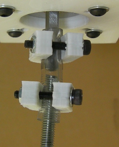
Start by fitting the couplings to the Z Motor. Inserting half of the tubing over the motor shaft. Next take one of the printed couplings and clip it over the motor side of the tubing as shown. Ensure that the gap in the coupling is aligned with the flat of the motor shaft. Then insert one of the M3 X 20mm cap screws and a washer into the hole in the coupling, and secure with a nut on the other side. Repeat this setup on the free side of the tubing; however leave the clamps on the free side loose.

Repeat this setup for the second Nema 17, and mount each of these motors to the Z motor mounts at the top of the frame using the 2x M3x10mm cap screws and washers on each.

Z Drive
|
 |
Begin by loosening the Z smooth rod clamp at the bottom and the Z motor mount at the top on one side, just enough so that you can slide the smooth rod out. Do not undo the clamps completely, as your machine has already been squared and will require realignment other wise. Remove one smooth rod, which you will use to test the X axis.
Insert the clip bushings into the X ends. You can curl them up so their ends overlap to insert them. Be careful. Check their internal diameter by running the smooth rod you removed from the Z axis through them. The rod should be held with no free play, but move smoothly with little force. If the rod is too tight (don’t force it), remove the bushing and use a small needle file to remove a small amount of material from the bushing holders. Use a thin screwdriver to dig out any plastic residue in the collar groove.
Alternatively put a 9mm drill bit in a vice, take the bearing inserts out, and gently ream out the printed part on the drill. Then use a 9.5mm drill bit, which is the actual size you want, and do the same VERY CAREFULLY. DO NOT use an electric drill! It will be far too aggressive. Again be careful – you don’t want to remove too much material and make a sloppy fit, or break the part.
Repeat this process until the rod just fits and slides smoothly, with both bushings in. It should not wobble from side to side.

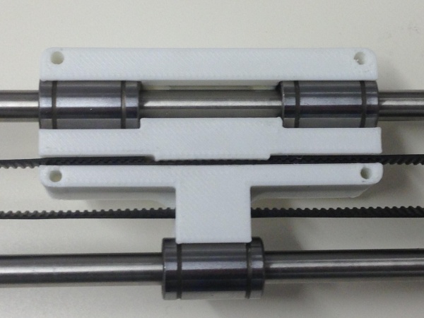
Next insert a spring and an M5 nut into the slots within the X ends. The nut should be placed at the top of the trap (the side with two linear bearings in the X carriage) with spring underneath as shown:

The two cap screws you put in the X end idler are adjusters that counteract the force of the X axis belt pulling in the X ends. The screws push on the ends of the X axis smooth rods. You can set the X axis to a particular width, so that when you attach it to the Z axis smooth rods it doesn’t bind as it goes up and down. Assuming your Z smooth rods are parallel!
Adjust the cap screws to ensure the clip bearings align with the Z bars. Replace the Z smooth rod you removed earlier, and pinch up the bar clamps so it holds it in place. Offer up the clip bearings on the X axis to the Z axis smooth rods. You should find the idler bracket needs adjusting outwards to correct the alignment. Tighten the adjustment cap screws in the end of idler bracket to push the x idler out, making the X axis wider.
Next thread the M5 studding into the nuts in the X end. Try to thread them in evenly such that the bracket is roughly half way along each piece of studding.
Loosen the Z smooth rod clamp at the bottom and the Z motor mount at the top on both sides, just enough so that you can slide the smooth rods up. Insert the Z smooth rod into the X motor mount clip bearings on the side of the machine with two linear bearings in Y. Tighten the Z axis smooth rod clamps, top and bottom. Use a rectangular object to support the X carriage on the Y Frog.
Slide the other Z axis smooth rod up, and then down through the X axis clip bearings, into its clamps and tighten. Check the X axis moves smoothly up and down; adjust the X idler screws if necessary.
Screw the ends of the M5 rods into the plastic tubes on the motors. Leave a gap of about 2mm to 3mm between the tops of the M5 rods and the bottoms of the motor shafts. (You can see this because the poly tube is transparent.)
Tighten the U clamps on the motor shafts and the M5 rods. Remember to have the flats on the motor shafts aligned with the gaps in the clamps.
Finally, use a ruler or digital calipers to measure the distance between the top of the X end and the top (or bottom – but be consistent!) of the Z motor mount, at each side of the machine. Adjust until the distance is equal on each side, by turning one of the Z motors by hand.


(Pictures show a Tricolour at a later stage of the build)
Z Endstop
|
 |
Use the M2.5 washers, nuts and cap screws to clamp the endstop to the endstop holder. You’ll notice that the endstop holder has four holes. The endstop should be clamped to the inner most two holes, with the nuts on the large flat side and the lever facing towards bar clamp. Use the remaining M3 fasteners to attach the bar clamp to Z smooth rod on the X motor side. The endstop should be positioned such that it is it is hit by the Z endstop adjuster cap screw.

The above picture shows the lever arm of the microswitch removed. The lever arm should snap off quite easily; just fold it back on itself. If you leave the lever on, you will need to cut down the length, because it is too long. It will either hit the Z smooth rod, or the Z leadscrew.
X Belt
Take the remaining belt left over from the assembly of the X axis. Insert one free end into the slot in the right end of the X carriage, so that it locks with the teeth of the small length of belt. It should be placed as far into the slot as possible, so that the end touches the edge of the narrow gap in the centre of the carriage. Then feed the belt into the X end Idler and around the small bearing, back through the carriage, around the motor pulley and back into the slot on the X carriage as shown below. Adjust the tension of the belt by loosening the X motor mounting screws, pull the motor back from the centre of the printer, then tighten the X motor mounting screws to hold the belt tight. The axis should move smoothly when pushed by hand, and the belt should be tight enough to make a just-audibly low note if you pluck it on it’s longest stretch.