
Contents
Preparing the bed surface
Some people are lucky, and are able to print directly onto the aluminium (for Huxley) or glass (for Mendel) bed surface, and the PLA sticks. Try it first, it may work for you. However, most people are not so lucky, and the sticking degrades over time, or different PLA has different properties and won’t stick. We provide a roll of Kapton tape with our kits, and PLA sticks very well to it. It can be applied to the bed surface in strips – try to keep the air bubbles out, and put the strips as close together as possible, but not overlapping. Only apply one layer. Kapton is durable: we use it in the production of kits, and will last at least a couple of months of 24/7 printing. Usually it peels up before the PLA won’t stick to it.
Blue painter’s tape can also be used. PLA doesn’t stick as strongly to it, and the surface isn’t as flat or durable as Kapton, but it is more widely available, and often in wider widths.
Cleaning
The bed surface needs to be completely free of all oil and grease (including finger marks), otherwise your prints won’t stick to it. We have found that the best stuff for cleaning the bed is cheap, Acetone-based, nail polish remover. Check the ingredients before you buy – the expensive ones have lanolin or other greasy materials in, which would obviously be bad for this application. The cheap ones just have acetone ((CH3)2CO), a little water, and maybe a tiny amount of glycerine and a compound called bittrex (which is supposed to stop you drinking the stuff…); these work really well. Wipe the bed surface thoroughly with a clean tissue dampened (but not soaked) in nail varnish remover.
You shouldn’t need to clean the bed after every print, but doing it regularly will mean fewer failed prints.
Other products that also work include Isopropyl Alcohol, White Methylated Spirits, White Vinegar. All of these are acidic, and dissolve oil and grease before evaporating. Don’t use Windex/Windowlene or polish; they often have a non-stick component!
Settings
RepRapPro 3D printers are being sold as a complete printing solution, as such the RepRapPro host software comes with pre-tuned print settings for PLA and ABS filament. We encourage people to play with and put forward improvements to the print settings, but would advise starting with the provided print profiles and working from there.
Some basic settings you may need to know:
Standard nozzle size – 0.5mm (0.3mm available as an option)
PLA printing temperatures: Hot end 200C, Heatbed 57C
ABS printing temperatures: Hot end 240C, Heatbed 110C
For extra notes on ABS printing, see our ABS troubleshooting page here
Preparing a file to print
Your 3D model will need to be processed into a format which the printer understands. This is known as a GCode file (machine movement commands are GCodes, [see this reference], and are common in the CNC world).
Required software
Before you can process a 3D model, you will need to install a slicing tool and tell Pronterface where to find it. Slic3r is recommended to get you started printing with your RepRap machine. This is available HERE. Click on the version for your operating system, and download the relevant compressed archive. Extract it into your Software folder.
Running Slic3r from Pronterface
In Pronterface, click on Settings | Options and check that slicecommand and sliceoptscommand point to the location of your slicing tool (ie Slic3r). You may be able to use relative paths, that is with a ‘.’ in front, but you may need to use the full path. This will depend on where you have put the ‘Software’ folder. For example, these may be:
Windows
slicecommand: ./Slic3r/slic3r.exe $s --output $o
sliceoptscommand: ./Slic3r/slic3r.exe
Mac
slicecommand: /Applications/Software/Slic3r.app/Contents/MacOS/slic3r $s --output $o
sliceoptscommand: /Applications/Software/Slic3r.app/Contents/MacOS/slic3r
Linux
slicecommand: home/[USERNAME]/Software/Slic3r/bin/slic3r $s --output $o
sliceoptscommand: home/[USERNAME]/Slic3r/bin/slic3r
If you put the Slic3r directory somewhere else, you will need to change the path for the above commands to point at it. You can usually see the path to the file by right clicking the Slic3r application and ‘get info’.
Profiles
Now get our pre-configured profiles, from https://github.com/reprappro/profiles/releases
Download and extract the zip into your Software folder (the one that contains pronterface.py), then point Pronterface’s sliceconfig option to it using the Settings | Options menu:
sliceconfig: ./profiles-master/
Again, your path may be different.
Running Slic3r independently of Pronterface
Generally, we now advise people to open Slic3r directly, and slice STL files in it, rather than using Pronterface to access Slic3r. This will give you much more information, views and control over slicing. However, if you open Slic3r directly, you won’t see our profiles. You’ll need to import our profiles into Slic3r to do this, or you can replace the default Slic3r settings with our profiles. First, open Slic3r directly, so it creates it’s default profiles folder. It may open a ‘wizard’ for settings, but just cancel this, and quit Slic3r.
Windows: the profiles are stored in folders under C:/Users/[username]/AppData/Roaming/Slic3r/
AppData is a hidden folder; you will need to change the View settings to see System folders, so you can find it. On Windows XP, the profiles may be stored in the same folder as above, or in C:/Documents and Settings/[username]/Application Data/Slic3r/
Replace the contents of the Slic3r folder above with the contents of the ‘profiles’ folder – the layout should be the same, with a ‘Slic3r.ini’ file, and sub folders for ‘Print’, ‘Filament’ and ‘Printer’. Run Slic3r to check that the settings are installed.
Mac and Linux: Slic3r creates a hidden folder in your ‘home’ folder called ‘.Slic3r’, for profiles. Replace the contents of the .Slic3r folder with the contents of the ‘profiles’ folder – the layout should be the same, with a ‘Slic3r.ini’ file, and sub folders for ‘Print’, ‘Filament’ and ‘Printer’. Run Slic3r to check that the settings are installed.
You can still open Slic3r, and slice, from Pronterface, just edit the ‘sliceconfig:’ setting in Pronterface settings, so it is blank. If you slice STL files in Slic3r, export the gcode file, and load this into Pronterface (or even better, copy it onto the SD card) to print.
Using Pronterface and Slic3r
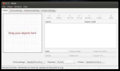
You should select a suitable profile for your machine, by navigating to the Settings | Slicing Settings menu option in Pronterface.
This will open the Slic3r software as shown below. Select profiles from the drop-down boxes along the lower part of the screen. The default configuration is a Huxley with a 0.5mm nozzle, using PLA filament. Close the window once you have set the profiles.
The 3D model will need to be in the STL file format. Pronterface can load either an STL 3D model (if you have set up Slic3r to slice the STL file) or a pre-processed GCode file (from Slic3r). Click on ‘Load file’ and select an STL file to process. You will see progress of this process in the log window, and it will create a GCode file in the same folder as the STL file. You can re-use the same GCode file whenever you want.
Once complete, the log will indicate how much filament will be used to print the model. You can then either print direct from USB (your .gcode file will have been automatically loaded) or copy the GCode file to the MicroSD card in the machine.
It is recommended to print from the MicroSD, for a number of reasons. When printing from USB, the print can be adversely affected by the host PC giving the printer a low priority over other running applications, slowing down the stream of commands. Also, the USB connection appears to be quite sensitive to AC noise on the power cable to the host PC.
To print from the SD card, copy the gcode file that you created in Pronterface to the card. This can be done through the printer interface with the SD card still in the machine, but it is much quicker to insert the card into the host PC and copy the file. When you reinsert the SD card into the Melzi, the board will reset communication with the host computer; this is normal behaviour. Simply reconnect to the printer by clicking ‘Port’ button in Pronterface, and select the new port that appears, then ‘Connect’.
Starting a print
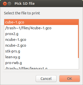
To begin a print, you need to select the file you wish to print. You can print an stl file (as above), or load a gcode file you created previously. If you are printing direct from USB, click the ‘Load file’ button to select the file, followed by the ‘Print’ button. If you have copied a gcode file to the SD card, select ‘SD Print’ from the ‘SD’ button, then select the file you want to print and click ‘Okay’.
Once the print starts, the machine will go through the following startup routine:
1. The printer moves all 3 motion axes in a negative direction to find X, Y, and Z zero.
2. The nozzle is heated to the relevant extrusion temperature.
3. Once extrusion temperature has been reached, the machine will print an outline before printing the component(s) to ensure the melt chamber behind the nozzle is primed.
When not required to move, the Z motors are de-activated. This can be a useful feature as it allows the Z height to be tweaked and the X axis to be levelled whilst the outline is being printed. Simply rotate the Z couplings by hand to get a good first layer (filament slightly squished). If you have moved the two couplings in unison to adjust the Z height, you will need to adjust the Z offset in the firmware before the next print, otherwise you will end up having to tweak the Z height manually at the start of each print.
Other useful software and links
Sometimes you get an stl file that doesn’t slice very well, or has holes in it, or other issues. Slic3r will often tell you if this is the case, and try to repair the file. You can check the gcode Slic3r has produced looks correct by clicking on on the gcode preview window (the yellow area) in Pronterface, and moving up and down through the layers in a 2D view. If you want a 3D view of the gcode, there are many options; you can upload the gcode to http://gcode.ws/ or use one of the many gcode visualisation programs.
Sometimes the stl model does need repair. The easiest thing to do is to upload the file to http://cloud.netfabb.com/ which will automatically repair the file for you. Alternatively you can download Netfabb Studio Basic from http://www.netfabb.com/downloadcenter.php?basic=1 which lets you manipulate the stl file. There are plenty of tutorials for using this on the internet.
Your first print
A good first print is one of the frame vertices from your machine:
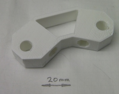
This is chunky enough to make a thorough test, and has some interesting features like horizontal holes, which require the machine to print on thin air (which it will do as long as the gap isn’t too big).
The file for this is on the RepRapPro Github repository here (right mouse click and select “Save link as”): https://github.com/reprappro/Mendel/raw/master/Print-mendel/Individual-STLs/frame-vertex-2off.stl. (The source OpenSCAD model is here if you want that: https://github.com/reprappro/Mendel/raw/master/Openscad/frame-vertex-readme.scad.)
Save the .stl file, load it up and print it!
Tuning your printer
X, Y and Z axis calibration
The X, Y, Z and extruder axis calibration are expressed in ‘steps per mm’. This defines how may ‘steps’ the stepper motor has to move to move the axis 1mm. Because the X, Y and Z axes are fixed mechanical systems, this is already set for you in firmware, and should not need changing. When printing, if parts come out the wrong size, more likely you have backlash (mechanical movement) in the axes, or you are over- or under-extruding. If you change the steps per mm settings of X, Y or Z, you may fix one problem, but exacerbate another. The extruder axis is somewhat different, as it can be affected by the physical properties of the filament. It is covered in the next section.
More information on setting X, Y, and Z steps per mm
To check your settings, send ‘M503’ to the printer. It should respond with the current settings in the Pronterface log window. Look for the M92 line, which will be something like:
echo:Steps per unit:
echo: M92 X87.489 Y87.489 Z4000.000 E660.000
The X, Y, Z and extruder steps per mm is set by this. We have shipped the following combinations of belt and pulley:
Original Huxley, Legacy Mendel:
White polyurethane belt (T2.5, 2.5mm tooth pitch), 14-tooth printed pulley: 91.4286 step per mm
Huxley, Mendel Mono and Tri from 1/4/2013:
Black rubber belt (MXL, 2.032mm tooth pitch), 17-tooth printed pulley: 92.635 step per mm
Huxley, Mendel Mono and Tri from 1/1/2014:
Black rubber belt (MXL, 2.032mm tooth pitch), 18-tooth aluminium pulley: 87.489 step per mm
You can change the steps per mm for any axis, or multiple axes, by sending M92 [axis][steps per mm]. For example:
M92 X87.489 Y87.489
M500
M500 saves this change to EEPROM, so it will stay correct if you turn the printer off and on again.
For reference, we currently supply 200-steps-per-revolution stepper motors (1.8 degree per step), use 16x microstepping, MXL belt (2.032mm pitch), and 18-tooth pulleys on the X and Y axis. On the Z axis, the thread pitch of the M5 rod is 0.8mm. If you change any of these, you can use these numbers to work out the steps per mm, where:
Steps per mm for belt (X and Y axes)
= ( motor steps per revolution * microstepping ) / ( number of pulley teeth * belt tooth pitch )
= ( 200 * 16 ) / ( 18 * 2.032 )
= 87.489
Steps for leadscrew (Z axis)
= ( motor steps per revolution * microstepping ) / thread pitch
= (200 x 16) / 0.8
= 4000
You can also use the above information to calculate the steps per mm using Josef Prusa’s calculator here.
Extruder calibration
The print profiles are tuned based on an assumption as to how much plastic is fed into the extruder for a given number of steps of the extruder drive motor. A critical parameter affecting the quality of the prints is how accurately the slicer knows the volume of plastic it is feeding into the extruder. In practice, this will vary slightly between machines. This is due primarily to the actual filament diameter, and to variations in the effective diameter of the hobbed stud.
The filament diameter should be measured and the value entered under the slicer’s Filament tab.
The E steps/mm setting can be adjusted without uploading new firmware, using M92 Ee, where e is the new E steps/mm value. By default the firmware has this set to 660. When this value is tuned, the top surface fill will have virtually no gaps between lines of filament, and no extra plastic at the ends of the lines. To check and adjust it do the following:
- With the machine off remove the tongue from the extruder drive;
- Wind filament through by turning the gear by hand; the end of the PTFE tube will come out of the drive;
- Wind through about 50mm of filament and cut it with sharp sidecutters about 5mm downstream of the drive;
- Carefully mark where the stub of filament is flush with the drive exit with a fine felt-tipped pen;
- Turn on the machine, send it an M302 command (allows for cold extrusion), and extrude 100mm of filament;
- Mark again with the felt-tipped pen;
- Extrude another 10mm and cut off your measured sample;
- If the sample is L mm long and your current steps/mm is e, then change e to be e*100/L; (using M92 Ee, where e is the new E steps/mm value, eg M92 E650)
- Send G92 E0 to reset the extruder zero point; without this, the next movement will be the incorrect distance!
- Run the test again to check you now get 100mm;
- To make the change permanent send an M500 command to store the values in EEPROM
- Heat the hot end up to temperature;
- Push a little filament through by hand from the 50mm you left sticking out, then pull the filament out to leave the path free;
- Reload the machine in the usual way.
If you are making this adjustment for a Tricolour Mendel, then also see Hint 3 here.
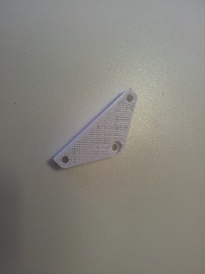
If the E steps/mm is set too low, a gap will separate the fill lines
A good test piece for this exercise is a 3mm high 30x30mm square.
Once you are happy with your E steps/mm value, you can edit your firmware as per these instructions. Please update your firmware even if you don’t need to change this setting; new versions come out regularly for fixing bugs (like the bug where an unplugged/failed thermistor means the heater goes to full power)!
Print another RepRap
So can I print more RepRaps in my RepRap?
Yes!
Your RepRapPro printer has been designed to replicate – that’s what the Rep stands for. Indeed, RepRaps are humanity’s first self-replicating manufacturing machines.
Replicating the plastic parts for another RepRapPro is easy. You can then use them to make a new RepRap (maybe with your own experimental design changes). Or you could make the RepRap plastic parts for a friend. Or you could sell sets of RepRap plastic parts to other reprappers on eMakerShop or eBay.
The Mendel stl parts are in /Print-mendel/Individual-STLs/ at https://github.com/reprappro/Mendel
The Huxley stl parts are in /Print-Huxley/Individual-STLs/ at https://github.com/reprappro/Huxley
The Extruder drive, which is shared between the Huxley and Mendel, has it’s own github repository. A RepRapPro Tricolour Mendel requires three such extruders, RepRapPro Mono Mendel and Huxley both need only one. The stl parts are in /Print-extruder-drive/Individual-STLs/: https://github.com/reprappro/Extruder-drive
You can buy a hardware only kit (no printed parts) from us HERE.
Profiles
Printing with different plastic may require modified print profiles. Have a look at http://reprap.org/wiki/RepRapPro_Huxley_print_settings for details, and if your plastic isn’t listed, please add to the table once you have worked out the best settings.
Changing Filament
- Heat nozzle to operating temperature.
- Extrude a little filament, like 10mm
- Set temperature to 100C, send M302 command (which over-rides cold extrusion)
- Wait for the temperature to drop to 100C, then reverse filament until it comes out of the extruder drive (about 380mm). You can do this at 600mm/min, or by hand if you wish.
- This should pull out most of the filament, hopefully down to the nozzle.
- Command M84 to turn the motors off. Feed the new filament in by hand.
- Drive/feed the filament to just before the hot end.
- Set temperature to operating temperature
- Command the filament to extrude short lengths at 200mm/min until it squirts out of the nozzle. You may need to hold the bowden tube straight for the filament to go down into the hot end easily.