
This page offers troubleshooting and additional information to the build instructions in case you have a problem with your RepRap. If you apply the solutions and fixes given and the problem persists please then contact the support department of the company who sold you the printer/Duet/kit. Make sure you list exactly what tests and fixes you have tried, and the results of trying each one.
NOTE: In all that follows do not unplug or plug in connectors with power applied either from the 19V Power Supply Unit (PSU) or from USB. The sequence should be:
|
Don’t be afraid to pick your RepRap up and turn it over when it’s switched off, then – if you need to – turn it on again. Fisher will rest on its sides (except the one with the filament reel spigot) or top with no problem. But remove the filament reel before you do this. Also, don’t drop it!
Duet 2 Maestro power problems
See the next section if you have a Duet 0.6.
- No LED turns on next to the USB socket on the Duet when Duet plugged into USB
- No LED or fan when the 19V Power Supply Unit (PSU) is turned on
- No USB or COM port appears on PC when USB is plugged in
Tests
Check the LEDs on the Duet
- When USB power is applied to the board, a red LED should turn on on the board, next to the USB socket. If power is supplied by 19V power, and no USB is connected, this LED does NOT illuminate. The 5V and 3V3 LEDs should also come on when USB power or 19V power is applied.
- If the ethernet is connected, a green LED should illuminate on the ethernet socket. This will illuminate with both USB power or 19V power. It flickers to indicate data transfer. (There is also an orange ethernet LED, which is a indicator for 10base-T connections – most modern ethernet hubs/routers/switches are 100base-T or gigabit, so the orange LED will stay switched off.)
- When PSU power is applied to the board, and with the wiring connected, the hot end fan should start spinning. All the power LEDs should come on, except the USB power LED if no USB is connected.
Test voltage
Test the voltage of the 19V line at the large screw terminals; using a multimeter set to volts, put the probes on the two screw terminals. If connected only by USB, you will get 0V here; if powered by the PSU 19V.
Solutions
- When the USB lead is plugged in, a red LED should turn on on the Duet next to the USB socket. If no light appears on the Duet next to the USB socket when plugged in via USB, check the cable, then check the USB socket. The USB cable may be faulty; try another, if available. It’s possible that your 5V USB power source (usually your computer) doesn’t supply enough current, to power the Duet, particularly if you’re working through a low quality USB power supply, an unpowered USB hub, or a laptop with low power USB ports. (The Raspberry Pi, which uses a similar ARM chip, also has this problem.) Plugging all the other connections in may also drain enough power to cause problems, particularly if there is a short circuit in your wiring. A solution is to use a powered USB hub; these will usually supply the proper specified USB current.
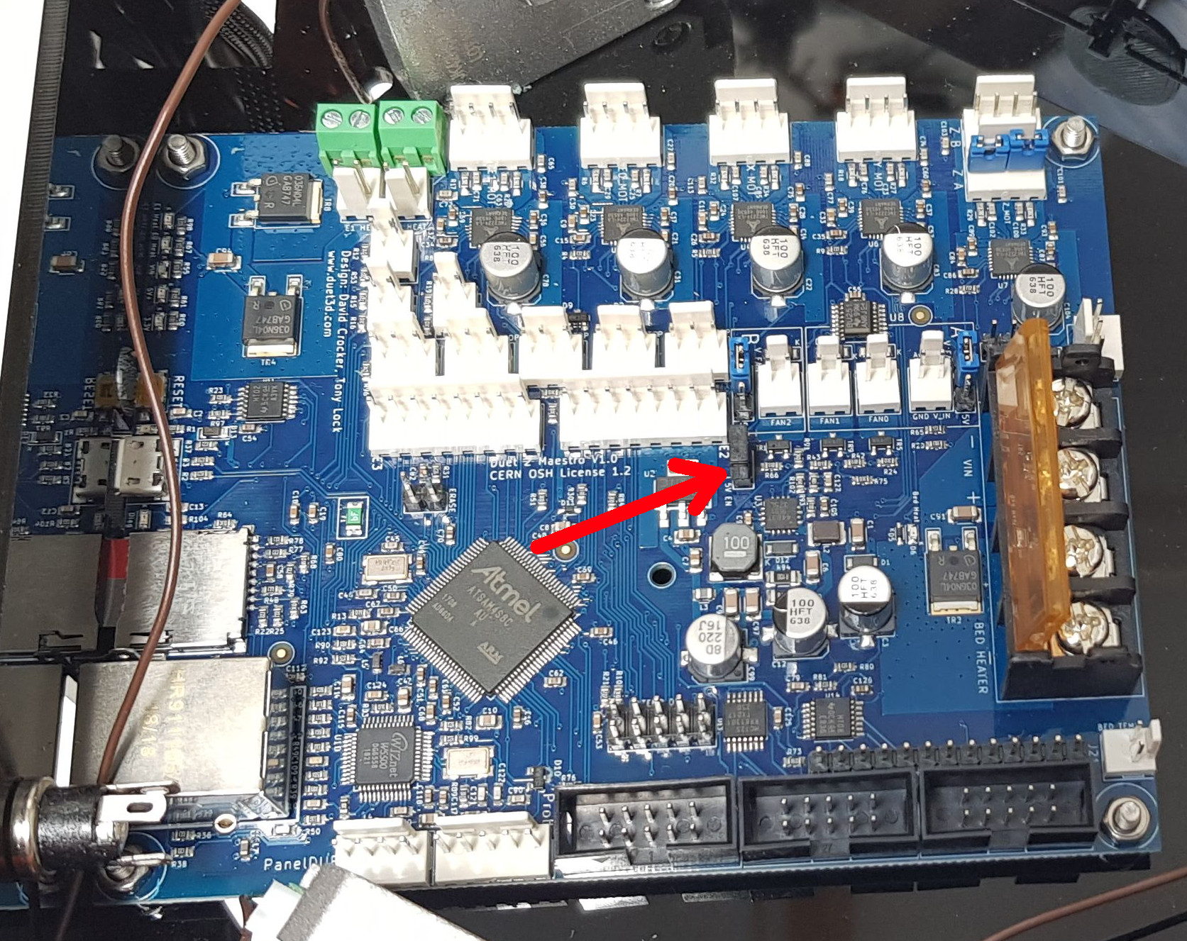
- If you have the PSU connected, and you get 19V on the screw terminals and the 19V LED is on, but no 5V or 3.3V LEDs without the USB plugged in, check that the jumper arrowed below is in place.

- Check to see if the main ARM processor (the biggest chip) on the board is getting warm/hot, under USB-only power or with the PSU connected. If there is a fault with the board, it can evidence itself by causing heat in the processor. There could be a short circuit in your wiring, or a fault with the board itself.
- Disconnect all looms from the Duet except the 19V power. Check if things work now. If they do, there may be a short circuit in your wiring. Check all the looms thoroughly. If they do not, contact support; your Duet board may have a fault with the 5V or 3.3V regulator, or there may be some other fault.
Further information and guides on the Duet 2 Maestro are available here
Duet 0.6 power problems
See the previous section if you have a Duet 2 Maestro.
- No LED turns on next to the USB socket on the Duet when Duet plugged into USB
- No LED or fan when the 19V Power Supply Unit (PSU) is turned on
- No USB or COM port appears on PC when USB is plugged in
Tests
Check the lights on the board
- When USB power is applied to the board, a red LED should turn on on the board next to the USB socket. If power is supplied by 19V power, and no USB is connected, this LED does NOT illuminate.
- If the ethernet is connected, a green LED should illuminate on the ethernet socket. This will illuminate with both USB power or 19V power. It flickers to indicate data transfer. (There is also an orange ethernet LED, which is a indicator for 10base-T connections – most modern ethernet hubs/routers/switches are 100base-T or gigabit, so the orange LED will stay switched off.)
- When PSU power is applied to the board, and with the wiring connected, the hot end fan should start spinning.
Test voltage
Test the voltage of the 19V line at the large screw terminals; using a multimeter set to volts, put the probes on the two screw terminals. If connected only by USB, you will get 0V here; if powered by the PSU 19V.
Solutions
- When the USB lead is plugged in a red LED should turn on on the board next to the USB socket. If no LED appears on the Duet next to the USB socket when plugged in via USB, check the cable, then check the USB socket. The USB cable may be faulty; try another, if available. It’s possible that your 5V USB power source (usually your computer) doesn’t supply enough current, to power the Duet, particularly if you’re working through a low quality USB power supply, an unpowered USB hub, or a laptop with low power USB ports. (The Raspberry Pi, which uses a similar ARM chip, also has this problem.) Plugging all the other connections in may also drain enough power to cause problems, particularly if there is a short circuit in your wiring. A solution is to use a powered USB hub; these will usually supply the proper specified USB current.
- If you have the PSU connected, and you get 19V on the screw terminals, but nothing works without the USB plugged in, but everything works with USB power, check that the jumper JP9 5V_EN below is in place.
- Check to see if the main ARM processor (the biggest chip) on the board is getting warm/hot, under USB-only power or with the PSU connected. If there is a fault with the board, it can evidence itself by causing heat in the processor. There could be a short circuit in your wiring, or a fault with the board itself.
- Disconnect all looms from the Duet except the 19V power. Check if things work now. If they do, there may be a short circuit in your wiring. Check all the looms thoroughly. If they do not, contact support; your Duet board may have a fault with the 5V or 3.3V regulator, or there may be some other fault.
- In the past we have seen issues with Mac OS X, where the Duet will show up when the firmware is erased, then disappear from the USB list when the firmware is updated. This will correct itself when you power everything off then on again. This should have been fixed in newer Arduino IDE software versions.
Connecting to the Duet by USB
Normally you will use the web interface to communicate with the Duet in your RepRap. But sometimes, especially if you have connection problems, it’s useful to connect instead (or as well – USB and web work together) via USB.
You will need a copy of the free Arduino Integrtated Development Environment (IDE). Getting that is described here.
Plug a USB cable into your Duet and your computer. In Windows the Duet will appear as a COM port in Windows Device Manager, or in Linux with a device name like /dev/ttyACM0, or in Mac OS X under USB in System Information.
If you are using Linux your user ID will also have to be a member of group dialout and the USB /dev device will have to be world readable and writeable. To do that run the following commands in a terminal window:
| $ ls /dev/ttyA*
/dev/ttyACM0 <- the Linux device of the Duet’s USB connection $ sudo usermod -a -Gdialout $USER $ exec su -l $USER $ sudo chmod 666 /dev/ttyACM0 (or whatever /dev/ttyACMn device the ls command found). You will have to give your password. The usermod command is permanent; you only have to do it once, no matter how often you connect or when. |
If you have USB connection problems, see the next section.
Run the Arduino IDE. In the Tools menu you should see the Duet USB port listed near the bottom. Run the Serial Monitor tool and you should get a serial monitor window like this:
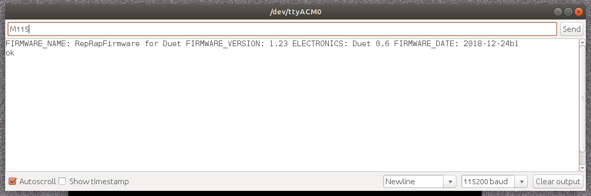
Bottom right set the speed to 115200 and line endings to Newline. In the send bar at the top write M115 and click Send top right. Your Duet should respond with its firmware version as in the picture. You can now send it any G Code you like and see the responses. Here is the page that lists all the G Codes.
The RepRap Firmware in the Duet accepts streams of G Codes from the web interface, from USB, and from any G Code file being run from its SD card and integrates them in a sensible way. This means that you can use both the web interface and the USB to talk to the Duet while it is printing. But, when a print is running, it’s not a good idea to issue a command that takes a lot of processor resources, like uploading a file.
Duet USB connection problems
- Duet is listed as a USB or COM port, but you can’t connect via USB
- Duet USB is not even listed as connected to your computer
Solutions
- When the USB lead is plugged in a red LED should turn on on the board next to the USB socket. Check the appropriate ‘Power problems’ section above if not.
- If the Duet is not recognised by your PC check the USB cable is fully inserted. The USB cable may be faulty; try another, if available.
- Check the voltages on the board – see the ‘Power problems’ section above.
- If the Duet still does not show up on your PC, it’s possible that the USB socket on the Duet is faulty, or loose, and the USB lines have broken. Check the USB socket; it has four legs that go through the board. All four of these should be soldered, to hold the socket firmly on the board. If they are not, contact support.
- Check if the Duet is recognised by your PC:
Windows: check that, when connected, the Duet shows up in the Windows Device Manager, in the ‘Ports (COM & LPT)’ section, as ‘Arduino Due’. If so, the firmware is running.
Mac OS X: Open System Information, and check if the Arduino is listed under ‘USB’. If it shows as a ‘Composite Device’, the firmware is running.
Linux: open a terminal window and send ‘ls -al /dev/ttyA*’. The Arduino should show up as, for example, /dev/ttyACM0 if the USB is working. - Has the firmware been erased?
Windows: In the Windows Device Manager under the ‘Ports (COM & LPT)’ section; if it shows as ‘bossa program port’, the firmware has been erased.
Mac OS X: Open System Information, and check if the Arduino is listed under ‘USB’. If it shows as a ‘Communication Device’ if the firmware has been erased. We have also had some problems with Macs not seeing the Duet; see: http://forums.reprap.org/read.php?340,509009
Linux: open a terminal window and send lsusb. If the Arduino shows as ‘Atmel Corp. at91sam SAMBA bootloader’, the firmware has been erased. - If the firmware has been erased, follow the firmware update instructions here.
- If the Duet is seen in the Windows Device Manager as ‘Arduino Due’ but you can’t access it by the Arduino IDE (and you are using the latest version), usually it’s because the device drivers haven’t installed, or are marked as ‘unsigned’ by Windows. You can try manually installing the driver, as described in the Arduino instructions here: http://arduino.cc/en/Guide/ArduinoDue#toc10 . On Windows 8, you may have to disable Windows Device Driver Digital Signing; see http://mytechblog.com/tutorials/arduino/install-arduino-drivers-on-windows-8/
- If the Duet is seen in the Windows Device Manager as something else, eg ‘GPS Camera’ or other device, there may be a clash between two devices on the computer, and both may have been assigned the same COM port. You will need to disable or change the COM port that has been assigned to the other device, or the Duet board. It may also be due to software installed on the computer, which is incorrectly identifying the Duet board, and taking over the communication, so that the Arduino IDE Serial Monitor cannot connect. See the step above about manually installing the driver.
- Check the port settings are correct. In the Windows Device Manager, in the ‘Ports (COM & LPT)’ section, right click on the ‘Arduino Due’ and open ‘Properties’. Check the ‘Port Settings’ tab. Windows sometimes sets the ‘Bits per second’ incorrectly – it should be 115200. Change this manually, or clicking ‘Restore Defaults’ should set it correctly. On Mac/Linux, the port settings are automatic.
- Open the Arduino IDE and check the settings are correct:
Tools->Board menu and select ‘Arduino Due (Native USB)’. If this is greyed out, check the device drivers have been installed.
Tools->Port menu and select the USB port for your Duet board; it’s usually named ‘Arduino Due (Native USB)’.
Tools->Serial Monitor, and make sure the communication settings are correct at the bottom of the window; select ‘115200 baud’ from the drop down menu, bottom right, and select ‘Newline’ from the other drop down menu. - For old firmware versions (pre 1.04), the Duet can take up to 1 minute to show up in the Serial Monitor if you don’t have the ethernet connected (this relates to old firmware; firmware after v1.04 starts up within a couple of seconds). Send any gcode, eg M115 (this checks the firmware version), and wait for up to one minute for the firmware to start up and respond.
- Check to see if the main ARM processor on the board is getting hot, when power is connected (USB or with the PSU connected). The processor usually runs at 20C above ambient temperature, i.e. around 40C, cool enough to touch with your finger. If there is a fault with the board, it can evidence itself by causing heat in the processor, and it may become too hot to touch, i.e. over 60C. There could be a short circuit in your wiring, or a fault with the board itself. Test again with all connections to the board removed, with just power applied to the Duet. Unfortunately, if the processor is overheating, the processor will have failed and the Duet will need to be replaced.
- For any other faults, contact support. Please explain clearly and completely from the list above what does, and does not, work.
Firmware update problems
- Cannot update firmware
- After firmware update, Duet no longer visible
Solution
- Check the instructions, and follow them carefully.
- If the bossac error is to do with the port not being found, try sending the update command without this part: –port=COMxx -U true .
- If the board is inaccessible following a firmware update, but then does reappear after the erase (Duet 0.6 only) and reset buttons are pressed, then when you send the bossac command, leave the -R off the end. Once the update has completed, wait for 10 seconds, then press the reset button on the board, and see if the board shows up correctly.
- If the bossac command still fails, make a note of the error, and contact support.
Micro SD card
If you have SD problems, try a different SD card, and writing files to it with a different adaptor. We supply Kingston Class 4 Micro SD cards and have had very few problems with them; they come with a guarantee from the manufacturer.
SD cards come in a variety of sizes; we have tested cards up to 8GB. They should be a FAT32-formatted disc.
- When you insert the SD card into your PC, you should see four folders – gcodes, sys, macros and www. These need to be the first thing you see, that is to say they should not be in another folder on the SD card.
- The SD card only goes in one way into the Duet SD card slot. Facing the Duet board so you can see the processor and other components, the writing on the SD card should face towards you as you insert it. You can damage the SD card slot if you force it in the wrong way.
- Have you pushed the SD card in fully? You need to poke it in past the lasercut panel with a small screwdriver or something similar. It should click in. To remove it, push it in again gently until it clicks again, then release and it should pop out.
- Test the SD Card is being read at startup by connecting using USB (see above), opening the Arduino Serial Monitor, and then send a command like M105. The correct response (with possibly different temperatures) should be:
M105
ok T:-273.1 B:-273.1
The important thing is the ‘ok’, which means the M555 P2 (Emulate Marlin USB output) command in config.g on the SD card has run. If you send M105 and get just:
T:-273.1 B:-273.1
(without the ‘ok’) config.g has NOT been read and executed at start up.
- If the SD card is working at startup, it’s generally safe to assume it will work the rest of the time.
- If it isn’t working, update your firmware if it is an old version (we have improved the firmware to help with the problem of slow cards).
- We now supply high quality Kingston 4GB Class 4 micro SD cards, and have experienced virtually no problems with these. If you have a non-Kingston card, try a different micro SD card – these are widely available and quite cheap.
- It could be dirt or dust in the SD card socket. Try cleaning the SD socket. Use an electronics/PCB/contact cleaning aerosol to clean the SD socket contacts; this should dissolve and wash away any contamination, and then completely evaporate. Or see this message on the forum regarding cleaning – http://forums.reprap.org/read.php?340,309685,310840#msg-310840 .
- Are you running on USB power only? If so, see this note regarding USB 5V power. If the voltage is below 4.7V on the 5V line, try powering the Duet from the power supply – for the moment, remove the hot end connector. Connect the 19V PSU, turn on, and test.
- Is the main ARM processor getting warm/hot? We’ve had a couple of people report that the SD card has shorted out the processor, due to manufacturing defects. Unfortunately, this is usually terminal for the Duet and means a replacement.
When you send the M503 command it should either print config.g (possibly truncated if it is long) or give an SD card error code. Here’s a list of the error code definitions:
- Error code: 0 or just ‘ok’ – Succeeded
- Error code: 1 – A hard error occurred in the low level disk I/O layer
- Error code: 2 – Assertion failed
- Error code: 3 – The physical drive cannot work
- Error code: 4 – Could not find the file
- Error code: 5 – Could not find the path
- Error code: 6 – The path name format is invalid
- Error code: 7 – Access denied due to prohibited access or directory full
- Error code: 8 – Access denied due to prohibited access
- Error code: 9 – The file/directory object is invalid
- Error code: 10 – The physical drive is write protected
- Error code: 11 – The logical drive number is invalid
- Error code: 12 – The volume has no work area
- Error code: 13 – There is no valid FAT volume
- Error code: 14 – The f_mkfs aborted due to any parameter error
- Error code: 15 – Could not get a grant to access the volume within defined period
- Error code: 16 – The operation is rejected according to the file sharing policy
- Error code: 17 – LFN working buffer could not be allocated
- Error code: 18 – Number of open files > _FS_SHARE
- Error code: 19 – Given parameter is invalid
Ethernet connection
| NOTE: DHCP is supported in firmware v1.09 or later. If the Duet is getting its IP address from the router via DHCP (IP address in config.g is set by M552 P0.0.0.0 S1 to enable this) and you can’t connect using the name of the printer (set in config.g by M550 P[name]), either your router does not support DHCP/NETBIOS naming, or your computer may be using an external DNS server, rather than using the router DNS. This would mean it can’t connect to a local IP address. Setting the Duet IP address manually should allow you to connect: change the M552 line in config.g to an IP address not used by your router (which should have an option to list those that it is using). You will set something like M552 P192.168.1.10 S1. The first three numbers should be the same as all the others on your router. The fourth should be unique and otherwise unused between 0 and 255 inclusive. Then if you simply type 192.168.1.10 (or whatever you’ve set) in the address bar of your web browser the Duet should connect. |
Physical connection problems
If you get no green or orange light on the Ethernet connector, either there is no power to the Duet board (via USB or from the PSU – it can’t be powered from the Ethernet connection), or the Ethernet cable is not making contact/isn’t working, or there is a problem with the Duet board. Check power and the Ethernet cable (see the first two sections above).
Testing the connection in isolation
For testing, disconnect your computer from the rest of your network, i.e. the router/hub/wifi connection, and connect an Ethernet lead directly from your computer to the Duet. This leaves a network between just your computer and the Duet. Set up the Ethernet port of your computer so it is in the same range as the IP address of the Duet. In config.g set something like M552 P192.168.1.10. Set the Ethernet port on your computer to 192.168.1.12, netmask 255.255.255.0, so it does not clash with the Duet addresses. Power the Duet just from USB and you should be able to ping the Duet to test it actually works.
To ping a network address: open a command prompt/terminal window, and type ping 192.168.1.10 (or the IP address you set in config.g). You should receive a list of sent/received data packets, which will show if the Duet is on the network. Even without an SD card, you should be able to ping 192.168.1.10 and get a response from the Duet.
You won’t be able to access the printer web interface, but it will prove that the network interface of the Duet works.
Check network settings
To connect to the Duet not using a DHCP connection (see above), you need to edit the settings in config.g so the Duet’s networks settings are in the same range as your network. The standard config.g IP defaults are:
;M552 P192.168.1.10   ; Set the IP address
;M553 P255.255.255.0  ; Set netmask
;M554 P192.168.1.1    ; Set the gateway
Edit the config.g on the SD card to uncomment (remove the ‘;’ characters) these lines and comment out the one above them that says M552 P0.0.0.0 S1. Choose values to suit your network.
Establishing connection
- If you disconnected your computer from the network, reconnect it.
- Make sure you have a working SD card (see above), and check the network settings.
- Connect ethernet cable to router, then to the Duet.
- Connect USB lead to Duet (this is needed for power, and can help with diagnosis), or turn on the PSU.
- The green LED on the ethernet connection should light up on the Duet and flash with data transfer.
- You should be able to ping the Duet, on the IP address you set.
- You should then be able to connect to the web interface using a web browser by typing the IP address you set in the address bar.
MAC addresses
If you have more than one Duet board on your network (i.e. more than one 3D printer), you will also need to change the MAC address of each additional printer in config.g:
M540 P0xBE:0xEF:0xDE:0xAD:0xFE:0xFD ; MAC Address
Subtract 1 from the last hexadecimal digit for each new printer: 0xFC, 0xFB and so on. No network can have two devices with identical MAC addresses.
Resolving other connection problems
- If you are using DHCP, check you are trying to connect to the right printer name, preceded by ‘http://[printer name]’. Also check that your router supports DHCP/NETBIOS naming, and your PC is not using an external DNS server and/or gateway. Some networks add endings on the names of devices connected by DHCP such as .local, .home, or no ending. Always finish the text you type in the browser’s address bar with ‘/‘:
- http://fisher1.local/
- http://fisher1.home/
- http://fisher1/
- If you can ‘ping’ the Duet IP address, the Duet is on the network, and the problem is most likely with the SD card or browser. If you cannot, it may be a problem with the Duet, or the network. Try changing the IP address in config.g as described above
- How is the Duet set up on your network? Is your network quite complex, for example an office network, rather than a simple home network? To remove network issues as a source, connect the printer directly to your PC, via a spare ethernet port. You can then set up the printer and ethernet port on the PC on it’s own subnet, separate from the rest of the network. Since firmware v1.04, you don’t need access to the internet. you should be able to ping the Duet, and then connect via the web interface.
- Clear the cache in your browser. It may be caching javascript code or settings of the wrong version, or corrupt. For Chrome, clear the cache, particularly any downloaded files/site data: https://support.google.com/chrome/answer/95582?hl=en-GB . In Firefox, clear the settings by clearing Preferences > Advanced > Network, then clear Cached Web Content.
- It’s possible that the files on the SD card have become corrupted. You may need to reformat the card (use the official formatting tool: https://www.sdcard.org/downloads/ ) then reload the files onto it. If possible, try another micro SD card. You MUST use the same version of the web server that is supplied with the firmware.
- Make sure that your router allows the Duet to run as a web server or service on your network. If it is blocking it, you would still be able to ping the Duet, but may not get a coherent response from the web interface.
- If you experience disconnections this usually happens with poor network access, or with network problems (going through multiple routers, hubs and over wifi). Usually, when it happens, resetting the Duet and closing the browser tab, then reopening, is enough to get rid of the problem and allow connection.
- If the above still doesn’t help and the browser produces any error messages, please contact support with a list of what you have tried and the output (if any) from each attempt.
Temperature sensing problems
- Temperature reports as -273oC, or below -10oC, or no temperature
- The USB interface reports a ‘temperature fault on heater …’, and the word FAULT appears against the heater on the web interface.
- Hot end never turns on
- During printing, the heater turns off unexpectedly
For the above faults see Testing Wiring and Resistances below. Instead you may have:
- Hot end end temperature reads 60oC at room temperature
For this fault, jump to the Duet Series Resistor section below.
Testing Wiring and Resistances
You will not be able to turn a heater on until any problem with it has been corrected and the temperature fault has been reset. After doing the tests below reset the fault by resetting the Duet (press the reset button on the Duet) or, you can send M562, which resets all heater faults. Then turn the heater back on in the web interface. Take care with repeated use of M562 – if you have a fault find and correct it, don’t keep resetting it and hope it will go away.
You are going to measure resistances with a multimeter to do these checks. If the multimeter readings are not stable, this can be caused by two things: the fault you are trying to find, or poor conections between the meter probes and the wires. If you are confident of the probe connections, which is to say you are pushing the probes onto what they are measuring quite hard, you can use the first possibility to find faults: while you hold the probes and measure the resistance, get someone else to wiggle the wires and prod connectors and so on. If, when they do that, the resistance changes, the thing they prodded was probably the fault.
Most commonly, incorrect temperature readings are a result of a poor connection in the thermistor wiring loom. This can happen at the connection with the thermistor, at any of the crimped connections, in any of the housings in the wiring loom, or even (rarely) a break in the wires of the loom. The quickest way to test is to use a multimeter, and to measure the resistance at the end of the wiring loom where it connects to the Duet. As long as your meter probes are sharp enough, you should be able to press them against the connector crimps in their shell, as shown. Unplug the loom from the Duet.
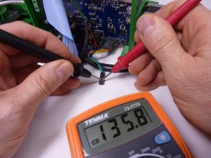
The resistance should give the ambient (room) temperature. The following resistances correspond with the following ambient temperatures:
| Hot end resistance | Temperature |
| 200 KΩ | 10oC |
| 160 KΩ | 15oC |
| 125 KΩ | 20oC |
| 100 KΩ | 25oC |
| 80 KΩ | 30oC |
To test the wiring loom you can also replace the thermistor with a known-value resistor. Plug the loom back into the Duet if you have disconnected it, then unplug the thermistor from the wiring loom at the hot end and plug in a resistor (100 KΩ is a standard value, and should give about 25oC as the web interface hot end temperature). Next unplug the Duet end and again measure the resistance at the Duet loom end. If it reports correctly, the thermistor may be damaged. If you don’t get a sensible reading, look for damage or failure along the wiring loom.
If you suspect the termistor is damaged, measure its resistance at the hot end with it disconnected from the loom. It should give the values in the table above if it is all right.
Test the Duet
If the wiring tests okay, you can test the Duet by connecting a known-value resistor directly to the thermistor pins, and see the temperature it reports (you can also do this using the wiring loom, and connecting the resistor in place of the thermistor at the hot end). For the hot end, find a 100k resistor, touch it to the thermistor pins on the Duet, and press the reset button on the Duet. Then connect to the Duet with the web interface, and check the temperature. The temperature should report around 25oC. The picture shows a Duet 0.6, but this works for the Duet 2 Maestro as well. (it also shows another resistor being used to check a heated bed thermistor.) Take care not to short anything when you touch the pins.
If you have a number of different value resistors, you can check the temperature across the range. Common resistor values give the following temperatures:
| Resistance | Temperature |
| 100 KΩ | 25oC |
| 47 KΩ | 42oC |
| 10 KΩ | 84oC |
| 1 KΩ | 173oC |
| 470 Ω | 212oC |
| 220 Ω | 261oC |
| 100 Ω | 321oC |
The above tests should show if the problem is with the wiring, the thermistor, or the Duet.
Solution
- If the thermistor appears to be broken, contact RepRap Ltd for a new thermistor.
- If there is a short circuit, or poor connection in the wiring, check/repair/replace the damaged wiring.
- The wiring loom may not be making good contact with the Duet header pins. If you have a Duet with no keyed headers (a little plastic part around the pins that aligns the wiring connection) the crimp in the loom housing can easily get distorted. The crimps in the housings are standard Molex KK 2.54mm crimps (e.g. from uk.rs-online.com ), and are a ramp-style connector. If the housing is not put on the pins straight, the ramp (the ‘curly’ part of the crimp) can get bent back, and a poor connection can result. You can remove the crimp from the housing quite easily (push down the little barb in the hole that retains it), then bend them back so they have better contact. You can also bend the pins on the Duet a little, to improve contact. You can, of course, replace the crimps and housings with anything you deem better, such is the nature of a kit build.
- If you have a Duet where the hot end temperature reads -273oC, or some other very low temperature, even with a 100k ohm resistor connected, there may be a fault with your Duet. You do need to the tests above to check it is not just a broken thermistor or poor wiring, though. If a 100k ohm resistor reads below 0oC we will replace the Duet under warranty. This fault is caused by manufacturing differences within each ARM processor at the heart of the Duet; the Analogue to Digital Converters (ADCs) on board the ARM processor can give quite variable readings at the limit of their sensitivity.
Unless you have the problem of the temperature reporting as 60oC at room temperature, you can skip the next section.
Duet Series Resistor Problems
- Hot end end temperature reads 60oC at room temperature
Solution
The Duet has a resistor in series with the thermistor. The two form a potential divider, and the Duet measures the volatage at the join to calculate the resistance of the thermistor, and hence the temperature.
Some old Duets use a 1 KΩ resistor for this. More modern ones use a 4.7 KΩ resistor. In the file config.g there is a line:
M305 P1 R4700 ; Thermistor series resistor
Which sets the value of that resistor. If you are getting temperatures around 60oC at room temperature change this line to:
M305 P1 R1000 ; Thermistor series resistor
That should fix the problem.
Endstop and homing problems
- Homing of X, Y and/or Z does not work correctly
- Axis moves the wrong direction when homing
- Axis does not stop before hitting the end
Solution
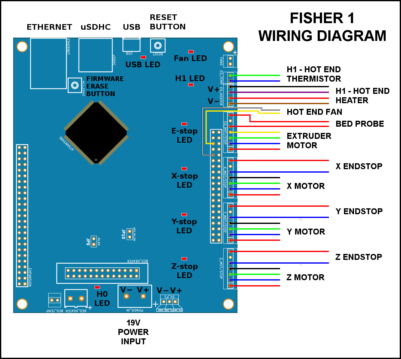
- Check that the motors are wired correctly; they need to be on the correct axis, and the right way around, on the Duet. See here for details.
- Check that the wiring looms are connected to the axis endstop microswitches correctly; they should connect to the outer two pins of each microswitch, NOT the central pin.
- Check that the bed is seated correctly in its cylindrical supports. See here for details.
Motor problems
- One motor does not move when commanded, when other axes do move
- Motor shudders, vibrates, or moves erratically
- Motor moves, but stops or stutters as it moves on the axis
Testing and solutions
| NOTE: Is it the extruder motor that’s not moving? From firmware v1.04 and later, cold extrusion is prevented by default. The extruder drive will not move if the hot end temperature is less than 170oC. You can override this behaviour, by sending M302 P1. See the Commissioning instructions here. Use the M302 command with caution. If you try to drive the filament while it is frozen in its nozzle either forwards or backwards the drive will abrade the filament instead of moving it. You will then have to take the filament tube out of its top pneumatic fitting, heat up the hot end, remove the damaged filament by hand, and restore everything. |
If there is a particular motor moving randomly, vibrating, or not moving at all, there are three things to check:
- The motor. These are generally very reliable – we have sent out over 10,000 of them, and had about 10 faulty ones.
- The wiring. This is also generally very reliable, but it’s possible it has been put together incorrectly, or there is a break in the wiring.
- The electronics. The Duet may have suffered damage to the stepper driver.
To test, turn off the power to the printer, and swap the wiring at the Duet between two axes, i.e. X, Y, Z, or the extruder. Make VERY sure you have connected the wiring correctly; check the wiring diagram (remembering that you have made the swap, obviously). Turn on power, connect, and test BOTH axes as instructed here. If the problem stays with the same motor as before, the issue is with the motor or wiring; if it swaps to the other motor, the problem is with the Duet.
If the problem follows the motor, turn off the printer, and replace the motor wiring on the correct pins. Then:
Check the motor wiring loom. Check that your motor wiring looms are connected to the correct pins on the Duet. We have had a few cases (in nearly 2000 kits!) where the motor loom is incorrectly wired. Compare the wiring loom, at both ends, with another, known-working motor loom; check that the colour order is the same (remember in the four colours that black and yellow are the same connection), check that the wires are connected to the right pins of the plug into the motor. The crimps are quite easy to release from the housing, and put in the correct order.
If you have a Duet with no keyed headers (a little plastic part around the pins that aligns the wiring connection) the crimp in the loom housing can easily get distorted. The crimps in the housings are standard Molex KK 2.54mm crimps (e.g. from uk.rs-online.com ), and are a ramp-style connector. If the housing is not put on the pins straight, the ramp (the ‘curly’ part of the crimp) can get bent back, and a poor connection can result. You can remove the crimp from the housing quite easily, and bend them back so they have better contact. You can also bend the pins on the Duet a little to improve contact. You can, of course, replace the crimps and housings with anything you deem better, such is the nature of a kit build.
Check the motor. It is possible there is a problem with motor, but this is rare. Connect the motor to a known-working wiring loom, and test it. Also, with the motor removed from the printer, rotate the motor shaft in your fingers. You will feel the magnetic steps as it rotates, but does it also feel notchy or gritty? There may be debris in the motor. The motors are quite simple; you can open them up by removing the 4 screws, then pull the end caps off. But if you do this, make sure there is no magnetic material nearby such as metal swarf or resistor wires; the motor has powerful magnets that will cause such materials to fly to them and stick; this is often hard to clean (even if you notice it). You can also check the soldering on the small PCB in the back of the motor. We’ll replace any motor that is faulty, under warranty, if you are unable to repair it yourself.
If the above doesn’t resolve the problem, the Duet may be faulty, most likely the stepper driver has failed. The main reason for this is a poor connection, or disconnecting the motor wiring when the motor has power going to it; for the technical explanation, see this page on the reprap wiki. If the axis has never worked, we’ll replace the board under warranty.
Random disconnections during printing
If the printer is resetting, and stopping mid-print, the cause is likely to be related to power interruption to the printer. Double-check that the 19V power input wires are well-seated in the screw terminals; they should be really solid. They have to carry a lot of current, and a loose connection here will generate heat, and possibly cause a disconnection/reset if the contact is poor. Once you are satisfied with this, check that you are getting 19V from the power supply when under load. Test at the 19V power input screw terminals, turn on the hot end, and see if the voltage drops. A small voltage drop of 0.5 to 1V is to be expected, but more than that can cause a problem.
If the printer is losing the USB connection, check the soldering on the USB connector.
If the printer is losing the USB connection and the soldering is okay, there can be a variety of causes. USB is quite prone to Electro Magnetic Interference (EMI), via the power line. Large motors and other inductive loads (in air conditioning, fridges, fans, drills and other hand tools and the like) starting and stopping on the same ring main can cause power spikes, while other high current devices, unstable mains supply, or poor USB power connectivity on the host PC can knock out the USB connection. If the printer seems to continue working without resetting (for example, if you are printing from SD card, it continues to print), this is the most likely source of the problem. Check that the USB cable is connected properly, and for any damage – a poor connection will be more susceptible. Customers have found that adding a surge suppressors, power conditioners or uninterruptible power supplies to smooth the mains supply, and using a USB cable with a ferrite core, can help if your mains is noisy.
General printing problems.
There is a useful pictorial guide to printing problems on all RepRap-style printers on the RepRap website here.
Poor or no extrusion problems
- Initial construction problems (if the nozzle has never successfully extruded)
- The nozzle is partially or fully blocked
- Extruder motor does not move much but makes a squeaking or clicking noise.
- Extruder motor rotates, but the gears do not.
- Extruder drive motor and gears rotate, but the filament does not feed.
- The extruder gears squeak, rub and/or get stuck as the big gear turns.
- The Bowden tube comes out of the pneumatic fittings
Hot end testing
- Disconnect the Bowden tube from the extruder drive. If there is no filament in the hot end and Bowden tube, insert a piece about 0.5m long. Check that it runs through the tube and into the nozzle smoothly. If it does not, see Construction below. Check the filament diameter is within tolerance (1.75mm, +/-0.1mm).
- Heat up the hot end to operating temperature (200oC for PLA), and push filament down the Bowden tube, by hand, to extrude. It should extrude filament with a small amount of pressure, and the extrusion should be smooth. If not, see Nozzle blockage below.
- Check the temperature of the aluminium cooling heatsink with fins – it should be cool to the touch, which the heatsink and fan are designed to achieve. If it gets hot, filament will melt further up the nozzle than it is designed to, and the pressure needed to extrude increases. See Construction below. You may have to disassemble the hot end if there is a plug of filament in the hot end.
- Remember these tips from the Printing page: Whenever you turn your Fisher’s power off, make sure the hot end has cooled below 60oC first with its fan still running. This will prevent heat flowing up the filament path in the hot end when the fan isn’t cooling the heatsink. Don’t leave the machine with the hot end hot for long periods (more than five minutes) not doing anything. The molten plastic in the nozzle will start to oxidise and to degrade. Turn the hot end off, then turn it on again when you need it.
Extruder drive testing
- Disconnect the Bowden tube. With no filament in the extruder, and the extruder motor turned off, turn the large gear by hand. Does it stick at any point? If so, most likely the gears are a little tight. See these instructions, especially the third one down.
- Load filament into the extruder. Turn the large gear by hand again. Does it turn smoothly and easily?
- Hold the filament tight, and turn the large gear. Does the filament slip? Check the hobbed insert has no abraded filament in its teeth. If you need to clean abraded filament out of the teeth, a sewing pin is useful. Check the filament diameter is within tolerance (1.75mm, +/-0.1mm).
- Using the web interface, command the printer to extrude (you will have to send M302 P1 to allow for cold extrusion). Does the motor move correctly? Don’t forget to reset cold extrusion prevention with M302 P0 when you’ve finished.
- For all of the above, see Extruder below.
Solutions
Construction
- Hot end cooling: Check that the hot end fan is on ALL THE TIME. If the hot end fan turns off, heat can travel higher up the nozzle, and the force of extrusion increases, eventually stopping extrusion. The hot end fan MUST run all the time (it should be wired to 19V directly on the Duet).
- Hot end cooling: Make sure the heatsink is installed so that the fan can blow air through it!
- Hot end construction: Check that the brass tapered nut is tight against the heater block on the nozzle. Tighten with spanners – more than finger tight! This will ensure the threads make good contact with the nozzle, and heat transfers well.
- Hot end construction: There should be space between the heater block and the heat sink; the heater block should not be up against the heat sink.
- Extruder drive: If the teeth of the hobbed insert have slipped on the filament, there may be pieces of plastic in the teeth, which the filament will slip on. Remove the filament, take out the big gear with the hobbed insert, then check and clean the teeth of the hobbed insert – a small wire brush or a sewing pin is good for this.
- Extruder drive: Check the bearings have washers in all the right places, or the bearings will have difficulty turning.
Nozzle blockage (also for changing filament)
To ensure the nozzle and melt zone are free from contamination, follow these steps:
- Heat nozzle to operating temperature (200oC for PLA)
- Extrude a little filament, like 10mm (if possible) by hand or via the interface, then set temperature to 100oC
- Wait for the temperature to drop to 100oC, then reverse filament until it comes out of the extruder drive (about 380mm). You can do this at 600mm/min, or by hand if you wish.
- This should pull out the filament from the melt chamber down to the nozzle, along with any contamination.
- Cut the contaminated end from the filament, and drive or feed the filament to just before the hot end.
- Set temperature to operating temperature
- Command the filament to extrude short lengths, 5mm at 150mm/min, until it squirts out of the nozzle (G Code: G1 E5 F150).
- Repeat steps 1 to 7 as necessary, usually at least a couple of times. If there is not improvement after 5 times, you may need to disassemble and clean the hot end.
- If you have to disassemble the hot end, try to clear all of the filament out of the hot end before reassembly. You can heat the nozzle up with a lighter (hold the nozzle with pliers) to soften the filament, and pull it out. If the filament has broken off inside the nozzle, heat it up and gently remove it with a 2mm drill.
Extruder
If the extruder motor does not move as expected, but makes a squeaking or clicking noise or just vibrates, it may mean it does not have enough torque to drive the extruder feed mechanism, because it is stuck or jammed.
- Check that the nozzle is not blocked (see solution above)
- Check that the idler bearing can rotate freely
- Check the diameter of your filament is not too wide (1.75mm, +/-0.1mm)
- If the motor vibrates rather than turning, even when not driving filament because there’s none in the drive, the stepper driver chip may be damaged or the motor connections may be faulty.
Extruder gear rotates, small gear does not
- It is unlikely the small gear will rotate on the motor shaft. But if it does, make sure the grub screw is against the flat of the shaft and tighten the grub screw.
- On the big gear, check that the hex head bolt is not rotating in the hex hole. If it is, again, you will need a replacement. As a temporary fix, you may be able to use epoxy glue or superglue to get the hex head to hold again. You can print your own replacement if you can get the glue to work, of course, but if your machine is still under warranty we will supply one if you prefer.
Extruder drive motor and gears rotate, but the filament does not feed. There are a number of potential reasons for this:
- The teeth of the hobbed insert have plastic in them. This will cause the teeth to slip on the filament. Clean the teeth with a pointy tool.
- The nyloc nut on the back of the large gear has come loose, and the hobbed insert is unwinding
- The filament may be too thin, or it is trying to grip on a section where filament has been worn away. Remove filament and check its diameter.
The extruder gears squeak, rub and/or get stuck as the big gear turns:
- There may be printing artefacts on the large and small gear, or they have been printed too ‘full’, so that they mesh very tightly. You can use a craft knife or sandpaper to improve the fit, or contact support to send you new gears.
- The large gear may be rubbing on the surface of the extruder body, or catching on the lower part of the small gear. Put a second M3 washer between the large gear and the first bearing, on the M3 hex bolt. This will lift the large gear away from the extruder body.
The Bowden tube comes out of the pneumatic fittings
- If the PTFE tube pushes out of the pneumatic fittings, it is probably not pushed far enough into them. It should go in about 19.5mm – the full depth of the fitting. Make a mark on the tube with a fine felt-tipped pen at 20 mm and you will be able to see how far it pushes in.
Finally, see also the final set of instructions for correcting the lengths of filament extruded at the end of the Hot end parts hit print, layers separate or are too thin, or too thick section below.
Filament doesn’t stick to the bed or parts warp problems
- If the first layer does not adhere well enough to the bed, there is a chance the component(s) will warp during printing.
Solutions
Cleanliness of build surface: The Buildtak bed surface needs to be completely free of all oil and grease (including finger marks), otherwise your prints won’t stick to it. Small pieces of molten plastic will adhere to the surface from bed probing and from the printing of the outline round prints to prime the nozzle. These can be removed with a scraper held at a very shallow angle to prevent its digging into the surface.
Tired Buildtak: Buildtak is robust and will last for many many prints. But it will eventually wear out and have to be replaced. It can be peeled off the lasercut bed. More Buildtak is available here.
Setting Z zero: At the Z home position, where Z=0, the nozzle should be just touching the bed. With everything calibrated and the bed probing having been run send G1 X0 Y0 Z0 F500 to put the nozzle in that position and check the absence of gap between it and the bed with a magnifying glass. Also check that it doesn’t collide with bed and push it down against its springs – the Z probe reading in the web interface should be 0. Follow the instructions laid out in the Commissioning instructions to correct Z zero faults.
Bed levelling and G32 problems
- Prints stick to the bed in some areas, but not in others
- Bed probing shows a bed map that is very distorted or has a pronounced slope
Testing
Make sure the bed is as close to mechanically level as possible first; see the endstop offset adjustment instructions.
No bed is perfectly flat, and the bed map should compensate for this completely. But if the G32 output is showing the bed map is very saddle shaped or distorted rather than just sloping check for a flat bed. Put a flat edge (such as a metal rule) across the bed in a number of different rotations, and see if there is light under the ruler, either in the centre, or the centre is holding the ruler off at the edges. For a sloping but reasonably flat bed see the previous paragraph.
Check that your G31 setting in config.g by following these instructions.
Do a repeatability test; if you run G32 multiple times, does the map stay consistent?
Solutions
- Poor or sticking movement of some of the tower axes (lubricate the linear bearings as described at the end of this section).
- If repeated bed mappings are consistent this proves that the bed contacts are working correctly. If they aren’t, the usual problem is that one or more of the spherical screw heads in the bed corners is not making reliable and repeatable electrical contact with its two cylinders. Check that the springs under the bed are not bent or distorted and are pushing squarly upwards. Tap the bed in its corners repeatably to seat it properly. Check when you do this that the probe reading always returns to 0 each time.
Hot end parts hit print, layers separate or are too thin, or too thick
- The fan duct is closer to the bed than the nozzle
- The nozzle is colliding with the print or parts that are being printed are knocked off the bed
- Vertical print walls are bulgy or seem to have too much material
- Prints seem thin and layers don’t weld fully to each other.
Solutions
- With the machine switched off and cold move the nozzle to touch the centre of the bed. The fan ducts should be about 5mm clear of the bed. If they are not, go carefully through the hot end assembly instructions – something has not been put together properly.
- Slight, non-damaging, collisions between the nozzle and the first couple of layers are to be expected. This is a good thing – it ensures those layers adhere tightly. But if the nozzle is subsequently colliding with the print as printing is being carried out this is almost certainlt caused by the extruder extruding too much plastic in the preceeding layers. The solution to the next problem will also fix this:
- If not enough filament is being extruded you will get the thin layer problem; if too much is being extruded yuo will get the bulge problem. In all these cases, you are going to extrude a known length of filament, measure it to check that the length is correct, then fix any discrepancy:
|
Axis sticking problems
- Axis doesn’t move smoothly
- Motor stalls when moving (sometimes all right at low speed, but doesn’t move far enough at high speed)
Solution
- Make sure rods are clean and linear bearings run smoothly. Take the bed out, then a little light oil (like 3-in-1 oil) will help lubricate the bearings and their seals. Home the axes half a dozen times after lubricating to spread the oil. Clean any excess of the tops of the bearings with a tissue. Smooth rods can be cleaned with wire wool or kitchen scourer to remove stubborn lumps. Put the bed back.
- On all three axes, check that belt alignment is correct, and the belt is not rubbing unduly on belt guides, its pulley or anything else.
- Check stepper motor current is not set too low in config.g. As standard this is set to 800 milliamps by this line:
M906 X800 Y1000 Z800 E800 ; Motor currents (mA)
- Check there is no mechanical obstruction to the movement of the belt, or bearings on the smooth rods.
- Check that the linear bearings are not contaminated or damaged. Do the bearings run smoothly on the rods individually, when removed? If the bearings still does not run smoothly, there may be contamination in the bearing. You can clean these out quite easily; washing them in petrol is usually easiest, and then put a little lubrication (see http://reprap.org/wiki/Lubrication#Linear_bearings for recommendations) in the bearing before fitting.
- If the bearing appears to have a manufacturing fault, contact support for warranty replacement.
Wobbly Z walls and non-circular circles
- Vertical walls are not accurately printed on top of each other
- Variability in layer height causes vertical walls not to be smooth
- Circular objects print out square
Solution
Generally we lump these problems together under the term backlash. This can happen on any of the axes, or a combination of them.
- Check belts are tight enough. On the longest free length, i.e. the side not attached to the carriage, pluck the belt. It should make a just audible, low pitch, twang. Tighten or loosen with the adjusters at the tops of the towers as needed.
- Check pulleys are not loose on stepper motor shafts – hold the motor shaft with pliers, then try moving the carriages while looking at the pulley
- Check that the axes are moving freely: see ‘Axis sticking problems’ above
- Check extrusion is consistent: see ‘Poor or no extrusion’ above
- Check that the arms are not loose on the balls at their ends. With the machine cold gently try moving the hot end/effector sideways by hand. There should be no slack or backlash, and no movement until one or more of the stepper motors moves to its next-magnet position (you will fell this as a series of detents).
Stepped layers
Partway through a print, the next layer appears to have slipped by a millimetre or two (or much more) causing a step which should not be there. This can be caused by:
- Axis belt slipping where it is attached to the carriage.
- Print head snags on part of the print, usually the print curling up or lifting off the bed. This can cause the belt to skip on the pulley, or the motor to stall.
- Axis snags on something. For example, the wiring catching/getting in the way of movement. This can cause the belt to skip on the pulley, or the motor to stall.
- Stepper driver chip in the Duet overheats and temporarily shuts down (rare and unlikely).
Solution
Belt slipping in carriage
- To test, hold the motor pulley tight and try and move the carriage. If it slips, secure it in place more positively. Add paper shim(s) as in the instructions here.
Nozzle hitting printed part
- The printer should generally have the power to overcome hitting a part while printing, and the bed can move down a little. However, if printed parts are curling up, particularly on overhangs or bridging, reducing the extrusion temperature 5°C at a time on a small (but not too small – at least 20mm x 20 mm cross section) test print will usually help.
- If the parts are curling up from the first layer, see the Filament doesn’t stick or parts warp section above.
Belt skipping on pulley
- Check belts are tight enough. The actual tension required comes with experience, but should be at least tight enough to produce a low frequency, just audible ‘twang’ on the longest section of belt. Over-tensioning the belts can also be detrimental, as the motors will have to work harder.
- Check that the belt is running smoothly and in line, and the edge of the belt is not snagging on the pulley and idler sides. With the motors off, check the axis moves smoothly – if not, see the Axis sticking problems section above.
- Check all wires, pulleys and belts whilst printing and reposition/realign anything impeding the smooth movement on all axes. This is easier with the lasercut top plate of the machine removed.
Stepper motor stalling
This is a result of the motor not having enough torque to move the axis (temporarily, since the print continues at the new position).
- Check that the motors are being supplied with sufficient current to meet the demand; See the setting in config.g in Axis sticking problems above.
- Use a secondary cooling fan to cool the electronics if they are getting too hot (this should only happen when printing in very extreme environments). Put three small equal blocks under the corners of the machine to lift it about 40mm off the surface on which it stands, and direct the output of a USB fan under it.