
Build Instructions – Base Assembly – Tower Assembly – Panels and Rods – Effector Assembly – Extruder Drive
Hot End Assembly – Electronics – Bed, Top Plate and Belts – Commissioning – Printing – Troubleshooting
First Print
The microSD image contains a sample sliced G-Code file: robot.g, which makes for a fun first print. Here is a suggested workflow from powering on the Fisher 3D printer.
You will see that we start by mapping the bed, as we did in the commissioning instructions. There are two reasons for this.
The first is that the new map will now include the bed probe offset that we worked out at the end of commissioning; this is clearly essential.
The second is that it doesn’t take long and it is a good idea to do this at the start of each print anyway. This is especially true if you have taken the bed out of the machine to remove a previous print from it. It can be put back in three possible orientations, and each will give rise to a different bed map.
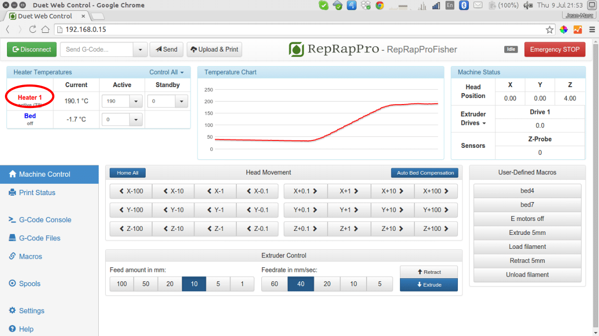
Click on Heater 1 to activate the hot end (or send T0).Set the temperature to 200oCIf you want to turn off the hot end, click on Heater 1 again to set it to ‘standby’ (or send T99) or click twice to set it to off. |
 |
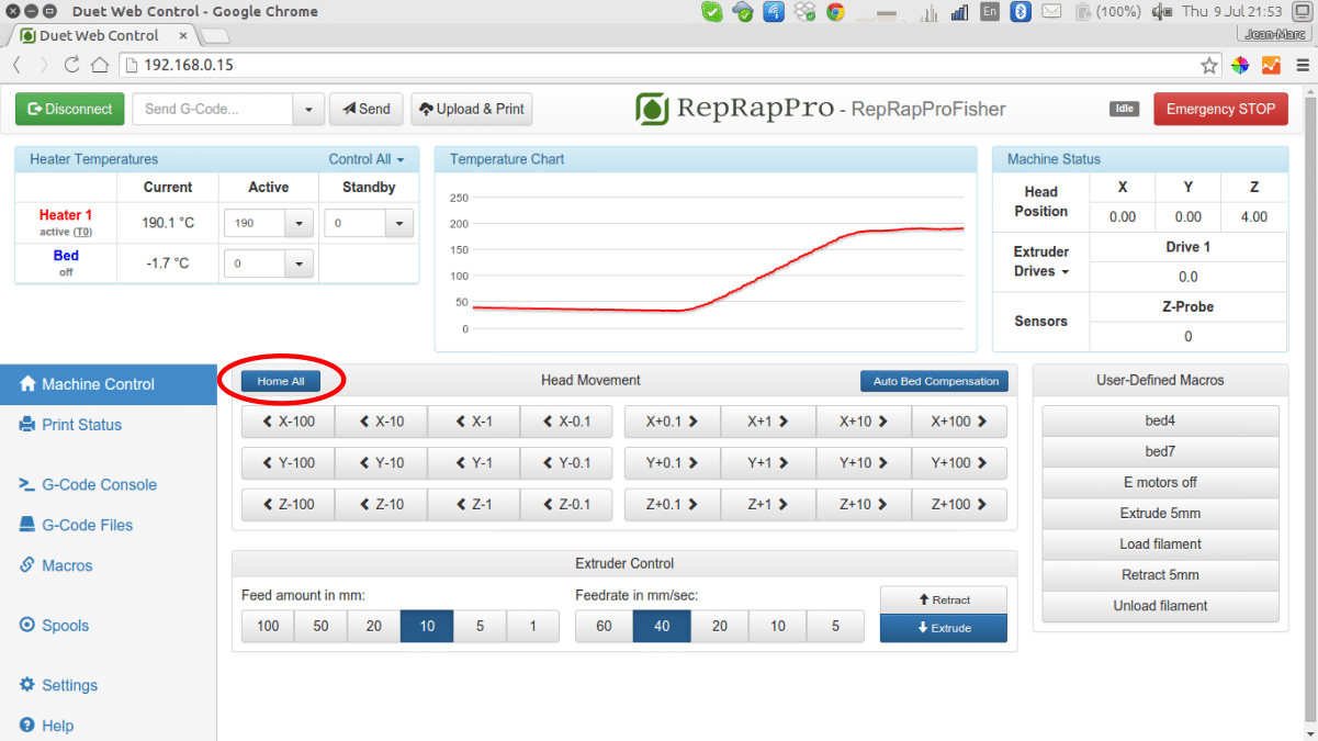
Click on Home All (or send ‘G28‘). Check the Z Probe value. This should be 0. If it isn’t one or more of the three bed corner contacts is not seated properly on its two cylinders. Tap the corners of the bed to re-seat it until Z Probe goes to 0. |
 |
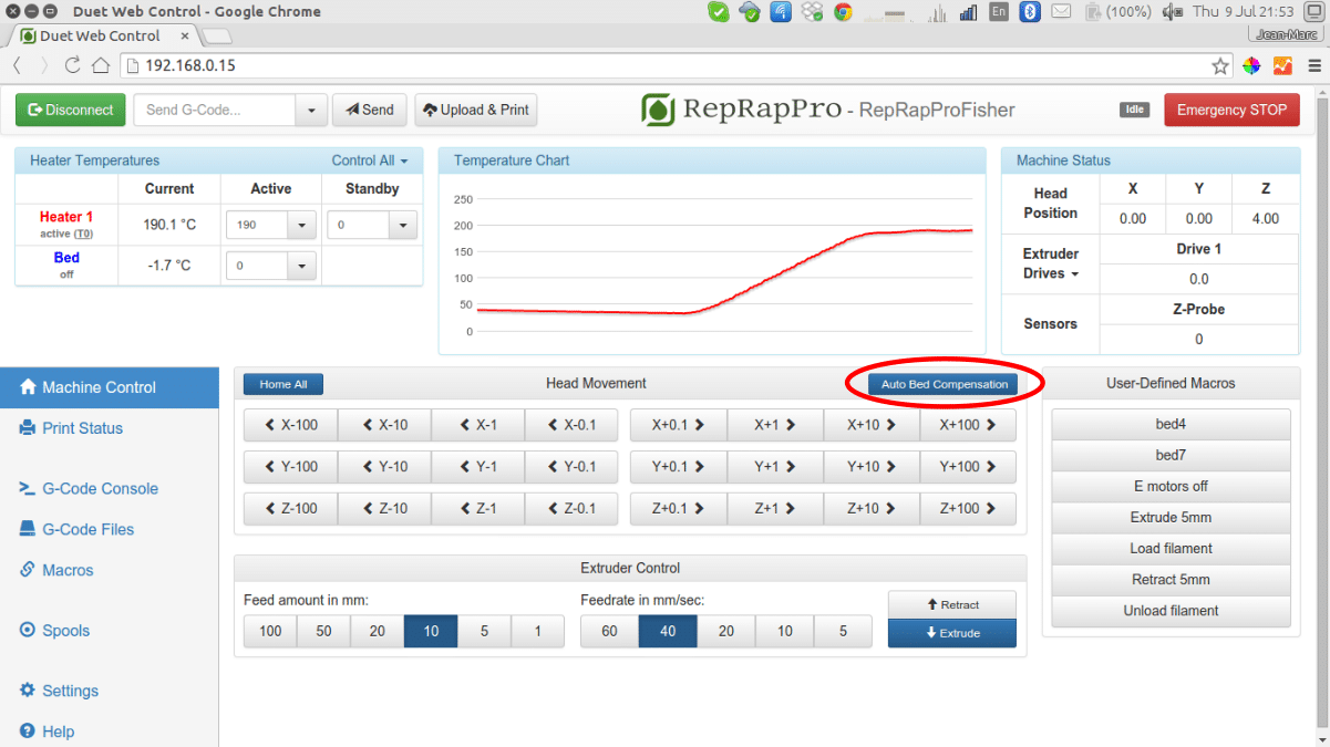
Click on Auto Bed Compensation (or send ‘G32‘). Always do this when the head is hot. If you do it when the head is cold any small pieces of filament stuck to the nozzle will cause the process to fail. When the head is hot, those pieces are molten and just move out of the way as the bed is probed. The file sys/bed.g will be executed. That will probe the bed in a grid and record a map of its surface. |
 |
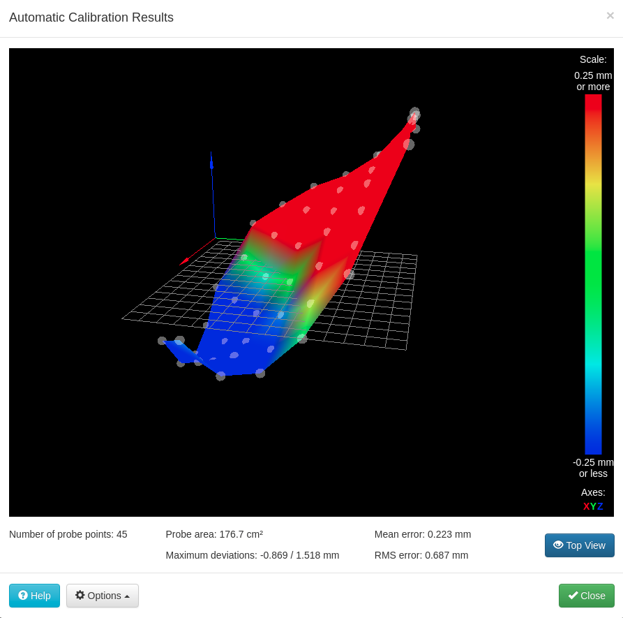
| The Duet firmware will display a map of the bed like this, which you can zoom and rotate with the mouse. The vertical scale is exaggerated, of course. As you can see, this bed had an overall slope, and was also not quite a flat plane. Both of these are normal, and the firmware will use this information to print at right-angles to the bed and to compensate for any slight irregularities in it. Select the Close option. |
|
| Navigate to the G-Code Files tab and click on Robot.g to print it. | 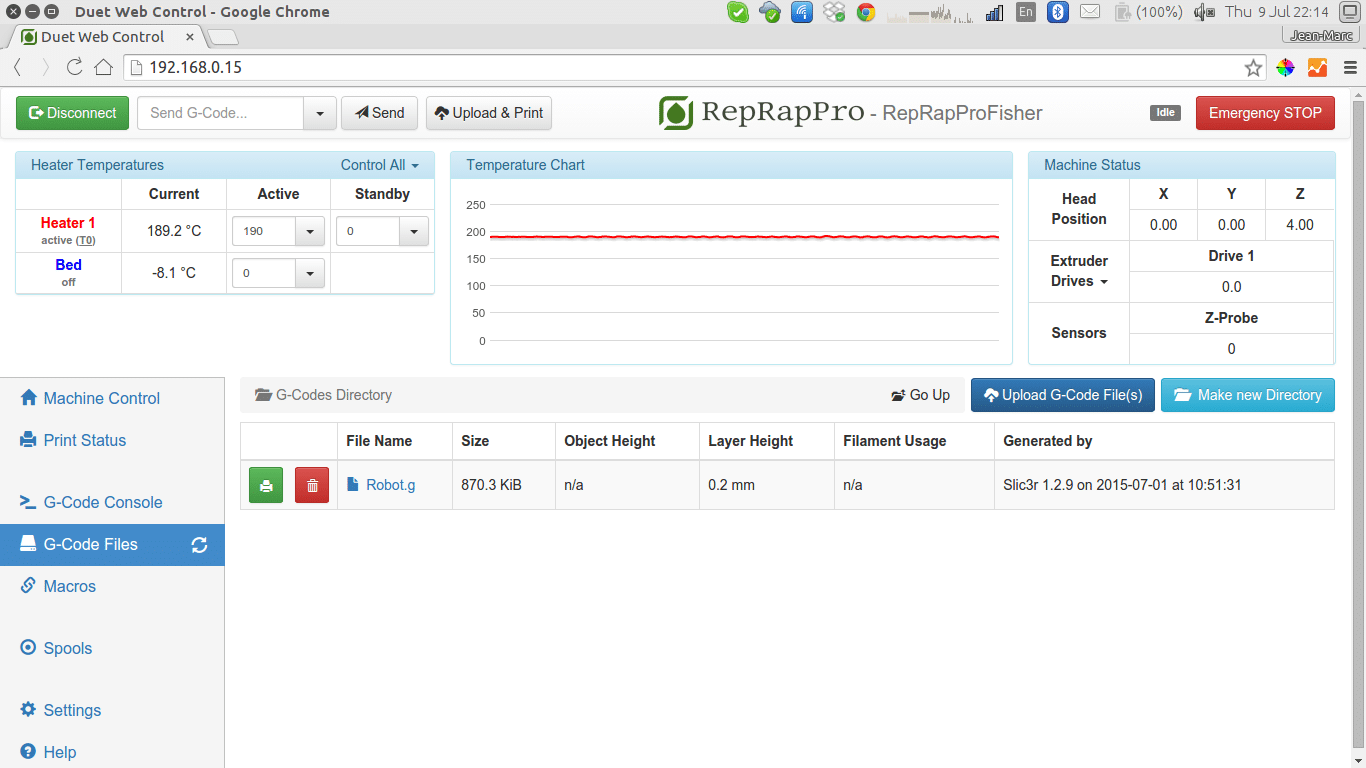 |
| When a print finishes, the Fisher’s heater should be turned off automatically. You can also turn it off by clicking on the heater button again.
|
|
| TIPS: Whenever you turn your Fisher’s power off, make sure the hot end has cooled below 60oC first with its fan still running. This will prevent heat flowing up the filament path in the hot end when the fan isn’t cooling the heatsink. Don’t leave the machine with the hot end hot for long periods (more than five minutes) not doing anything. The molten plastic in the nozzle will start to oxidise and to degrade. Turn the hot end off, then turn it on again when you need it. |
Final calibration
|
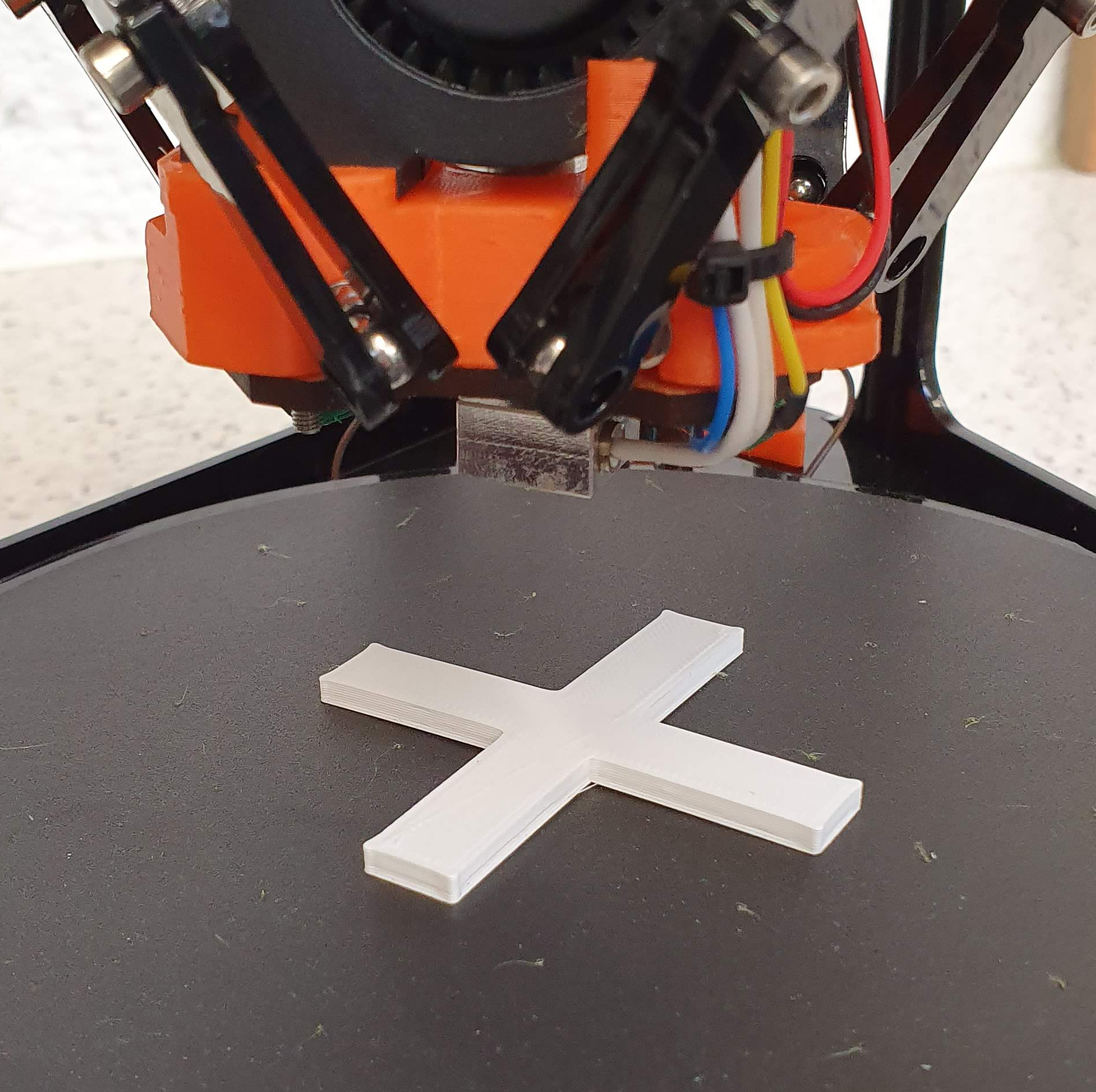
There is another G-Code file on your SD card called test-cross.g .
This is a cross the limbs of which are 60mm long. Print this file. |
|
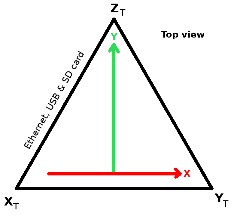
| Before you remove it from the print bed, use a felt tipped pen to mark on it the X and Y directions relative to the side of your Fisher that the power and Ethernet wires connect to as in the diagram on the right.
Take the cross off the bed and measure the X and Y arms of the cross and jot down their lengths. When you measure be careful to avoid any slight flash that may be projecting a small amount at the first layer of the print. Let your measurements be x and y. On the web interface, go to Settings->System Editor, and edit the file config.g . At the end you will find these lines:
Change the X and Y values from 1.0 to the result of calculating 60/x and 60/y respectively. Save config.g, and reboot when your Fisher asks you to. |
 |
Preparing Your Own Files for Printing
Having celebrated your success and shown all of your friends and family, you can now move on to preparing you own 3D models for printing. There are three steps to the printing process:
- Obtain 3D model
- Process 3D model to create a print file containing all of the instructions the machine will interpret in order to create the object. This is known as slicing.
- Upload and print G-Code file
Obtain 3D Model
The first step is to obtain the 3D model of the object you wish to print. There are a number of options available to achieve this:
- Find a 3D model online. There are many websites setup to provide 3D models to download, either for free or a small fee. There is a list of websites where you can download models on the RepRap Website here.
- Find someone willing to create the 3D model from your ideas.
- Create your own 3D model. There are many software packages available for this. Again, there is a list on the RepRap Website here. You want 3D CAD software. Check that the software you choose can export 3D designs in STL format (almost all of them can).
Slice
We recommend the free and open source software Slic3r. You may download the latest version from here. Once installed, Slic3r will present you with a first run wizard to setup some settings for you machine. You may skip this and use the profile we use. You will find a copy of this on your micro-sd card; alternatively, if you download our Fisher repository, the folder is in Fisher/Software-Duet-0.6/.Slic3r or Fisher/Software-Duet-Maestro/.Slic3r (the two should be the same, there’s just a copy in each Duet folder for convenience). The folder is called .Slic3r, which is the same as the configuration file that Slic3r creates in your home folder when it is first run. Overwrite the one Slic3r creates with the version from our repository. Note that the folder is hidden, as its name starts with a “.”. You will have to set your file browser to view hidden files to see and to copy it.
You are now ready to slice your own models. Run Slic3r and click on Add…, then choose the STL file of your 3D model. You can also drag-and-drop STL files into the view of the circular Fisher bed.
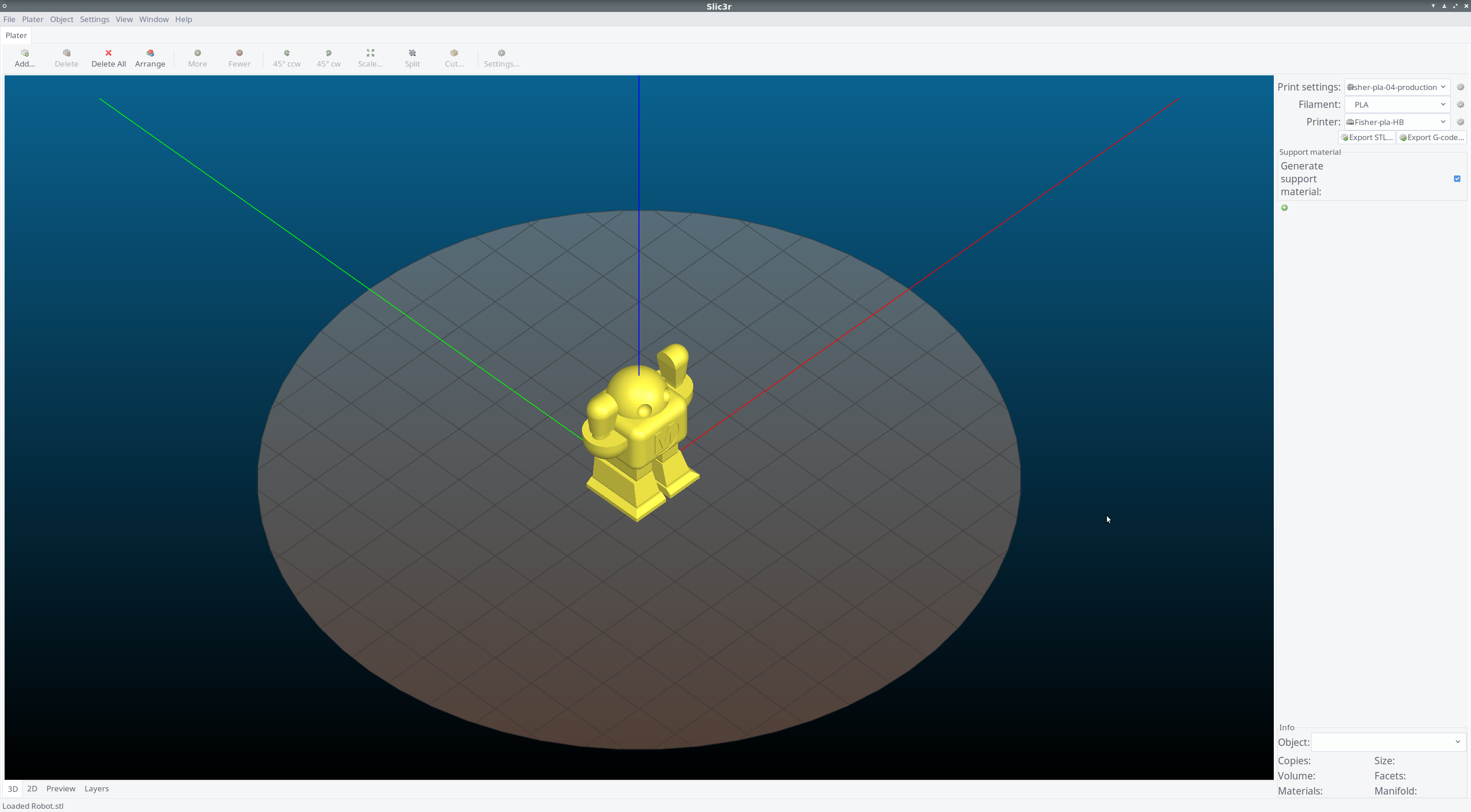
Click on the Preview tab to verify the toolpath, modify any settings as required, then click on Export G-Code. Make sure you wait until Slic3r says the file export is complete.
Upload and print
The .g file can then be uploaded via the web interface (just drag and drop it onto the upload button in the G-Code Files section) and printed.
What to print next?
RepRap is short for replicating rapid prototyper. It’s open source and can be freely copied by anybody. You now have a fully functional RepRap 3D printer. Why not print another set of RepRap parts and give them to a friend, local school or community project to carry on the replication? We have hardware only kits available to go with your set of printed parts. All the G-codes are included in the SD image and the design files and STLs are all available on our Github repository. If you make any design improvements or changes, let us know and these may be included in our next update.
Back to Commissioning