
Build Instructions – Base Assembly – Tower Assembly – Panels and Rods – Effector Assembly – Extruder Drive
Hot End Assembly – Electronics – Bed, Top Plate and Belts – Commissioning – Printing – Troubleshooting
Goal
By the end of this section, your Fisher will be ready to print.
Make sure you set aside time to do the whole of this session in one go. If you turn the machine off and on again in the middle of these instructions then some previous states of the machine you have established in the early sections will not be available for the later ones.
| Before applying 19v to the machine, confirm there is no short in the dc power circuit by measuring the resistance between the screws of the power input screw terminal. There should be very high resistance, or infinite resistance, i.e. no connection, between these two terminals.
As you first connect the meter the voltage it applies to measure the resistance will charge the Duet’s capacitors, so the resistance will start low then rise. The measurement you want is when it stabilises. |
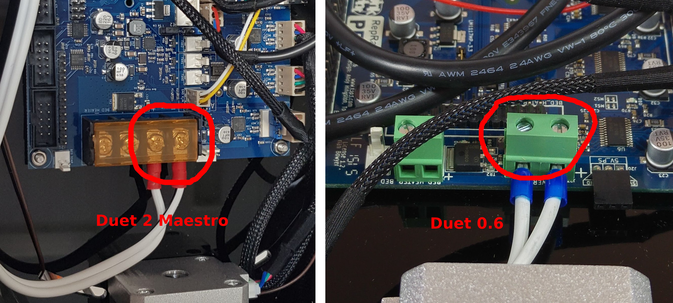 |
Now connect the power supply to the machine, power it on and make sure the 19v hot end fan comes on.
If it does not, TURN OFF THE PRINTER IMMEDIATELY, and check your wiring. Otherwise, wait a few moments (maximum 20 seconds) and check for overheating of the nozzle. At this stage, the nozzle should remain at room temperature, so if you see smoke emanate from the nozzle, switch the machine off IMMEDIATELY and check your wiring. Take care. If the heater comes on it will get hot enough in seconds to burn you. Touch it with a licked finger, like testing the temperature of an iron.
If the hot end does heat up, you have most probably wired the hot end connector incorrectly, with the hot end heater being connected to the fan output. So rather than the fan being on all the time, the heater is on all the time.
First Connection
| Sometimes the Duet is supplied with its SD card already in its slot. Sometimes it is in a separate packet.
If it is not already in the Duet, unpack the micro SD card. With the power off, push the micro SD card into the socket in the Duet. As the Duet is upside down in the machine, the microSD card should be inserted with the contacts face up, until it clicks. Note that Fisher will not work without the SD card inserted, and it should never be removed when the machine is powered on. Connect Ethernet and power to the machine. The machine should connect directly to a router via the Ethernet cable. You will then be able to operate the machine from a computer connected to the same network (either WiFi or Ethernet). |
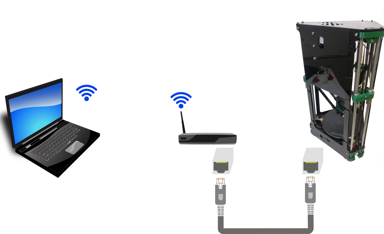 |
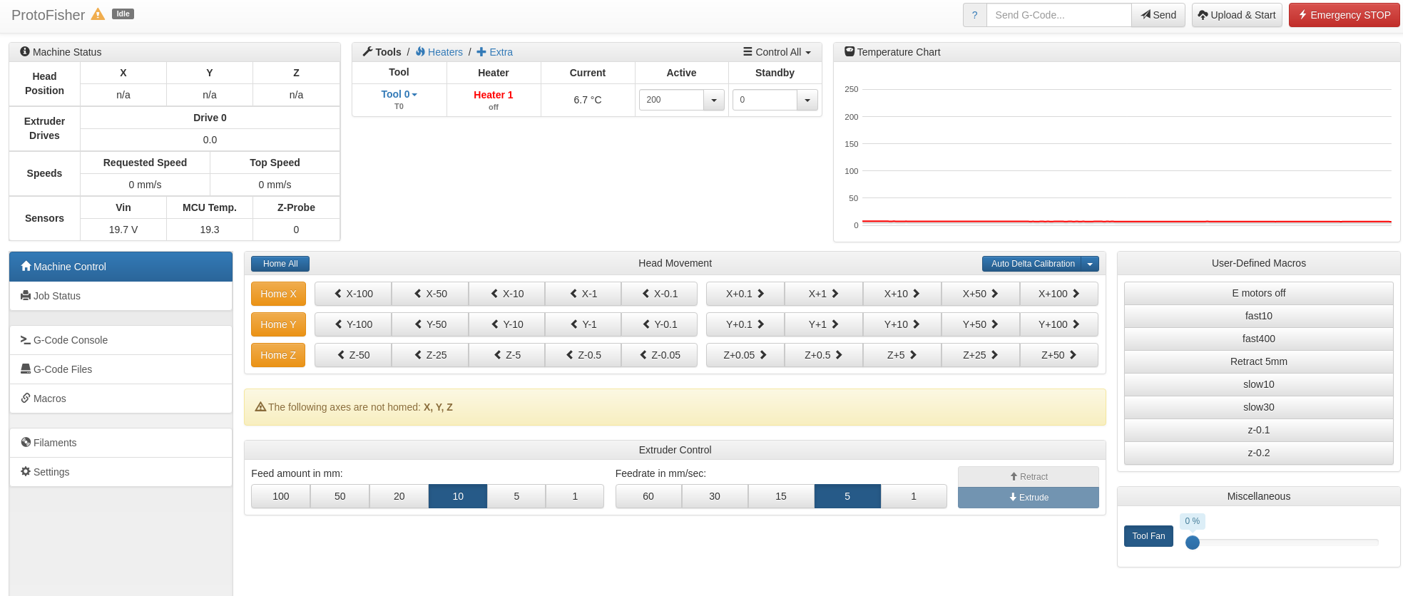
| Open a web browser and navigate to: http://fisher1.local/ This will show the web interface and will automatically connect if the machine is found. In the case that your network router cannot resolve the machine’s name (some use .home/ rather than .local/, for example), you will need to type your machine’s IP address into the address bar. To find the IP address of your machine log in to your router and get it to list the devices connected to it. If this fails, please see the troubleshooting guide here. |
|
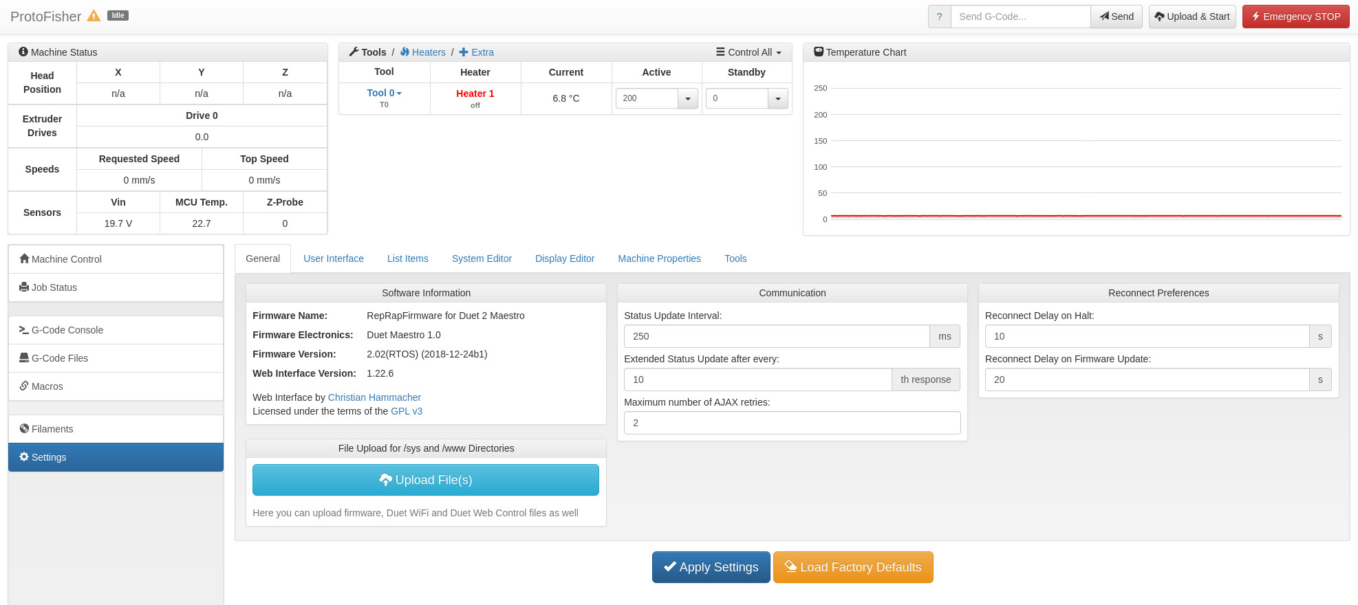
| Navigate to the Settings tab and verify the firmware version, which should be 1.23 or later, and a web interface version 1.22.6 or later. If you have earlier firmware, update it using the instructions in this link. |
|
By default, the Duet is set up to get it’s IP address by DHCP. You can set up the Duet on you network a number of other ways; see here.
If you cannot connect by Ethernet, you can run your Fisher from the USB port. Follow the instructions from the Troubleshooting page, which will guide you through setting up communication and connecting. Once connected in the Arduino IDE by USB, come back and follow the instructions in the following sections, then get the we interface working (which is also covered in the Troubleshooting page).
G-Codes
Every aspect of Fisher’s control is achieved by G-Codes. These are standard instructions in ordinary text that you send to Fisher for doing things like moving the machine to a certain position, turning heaters on, and so on. For most regular use, the web interface generates these and sends them automatically. But for commissioning we need to send some specialised ones by actually typing them. The web interface allows you to do that in a G-Gode console page. You type the commands, send them, and that page echos what you sent and also (if there is any) gives you the response from the machine.
If you are interested, there is a complete list of all the G-Codes together with detailed explanations here. There are a lot…
In the sys folder on the SD card there is a special file of G-Codes called config.g that is run every time Fisher starts to configure it. You will be making some small changes to that file to configure your particular machine in what follows. The web interface allows you easily to edit config.g.
Despite all being called G Codes, G Codes can actually start with one of three capital letters: G (movement and other fundamental commands), M (ancilliary commands), or T (tool – i.e. hot end and extruder drive – selection).
Axis Motion
| On the four motors, check all the grub screws in the three belt pulleys and the extruder drive and make sure they are all tight. | 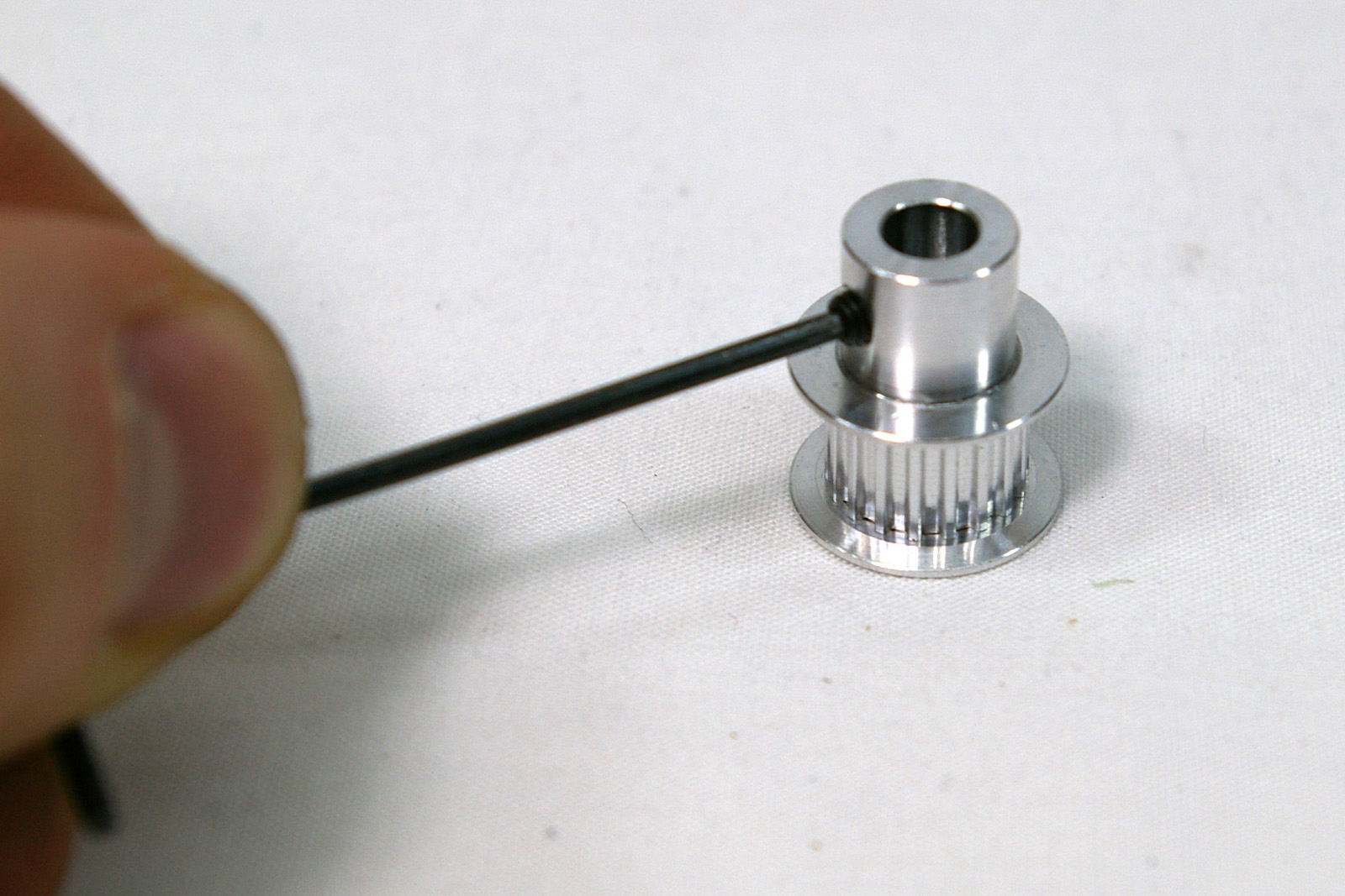 |
| Now test the motion of the axes. Navigate to the console tab then set incremental mode by entering and sending the following G-code:
Incremental mode says move by a certain distance (as opposed to absolute mode – G90 – which says move to a certain position). Put Fisher back in absolute-move mode by sending:
|
 |
Endstops
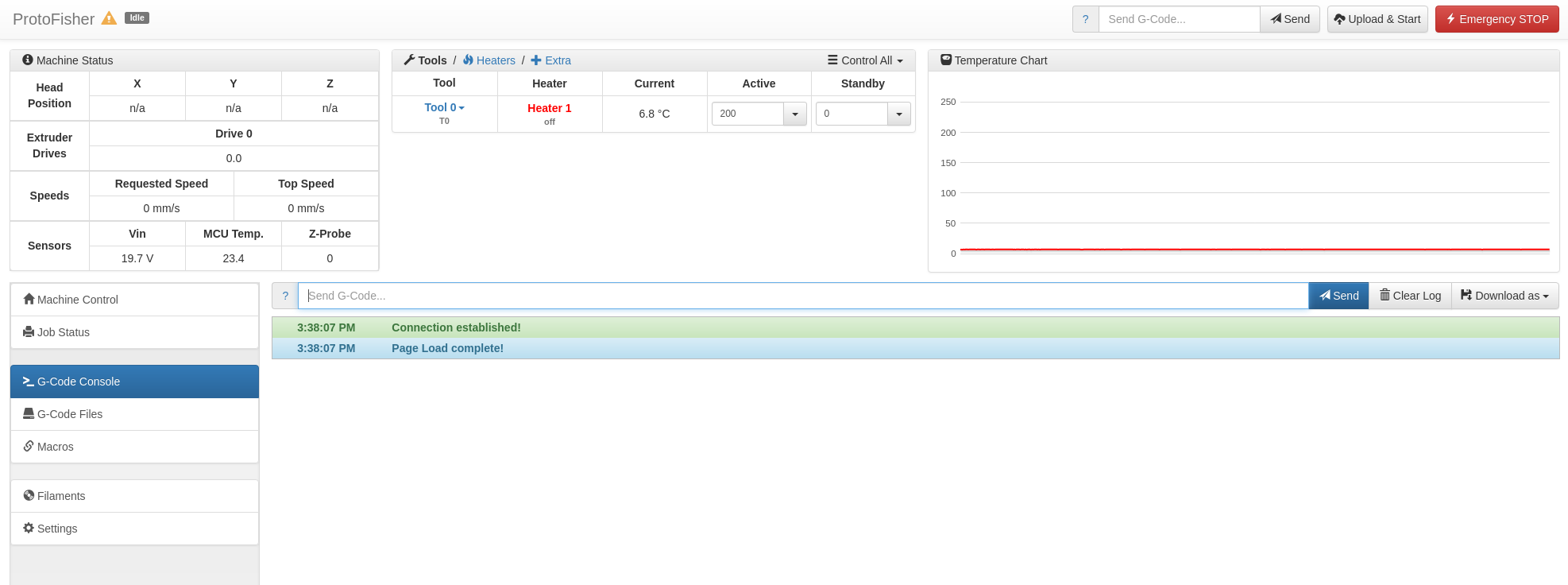
| Now confirm the machine registers triggering of the endstop microswitches. Navigate to the G-Code console tab, then send a command to check the status of the endstops:
The response should be: If the response is not correct, check your wiring:
Finally send:
This will power off the motors for the next step. |
 |
Homing
Homing is driving the machine to the endstops so that it knows where everything is. This is normally done just after you turn Fisher on.
| Make sure the Hot End and Effector are in the centre of the machine. You can move them by hand as the motors are powered off. | |
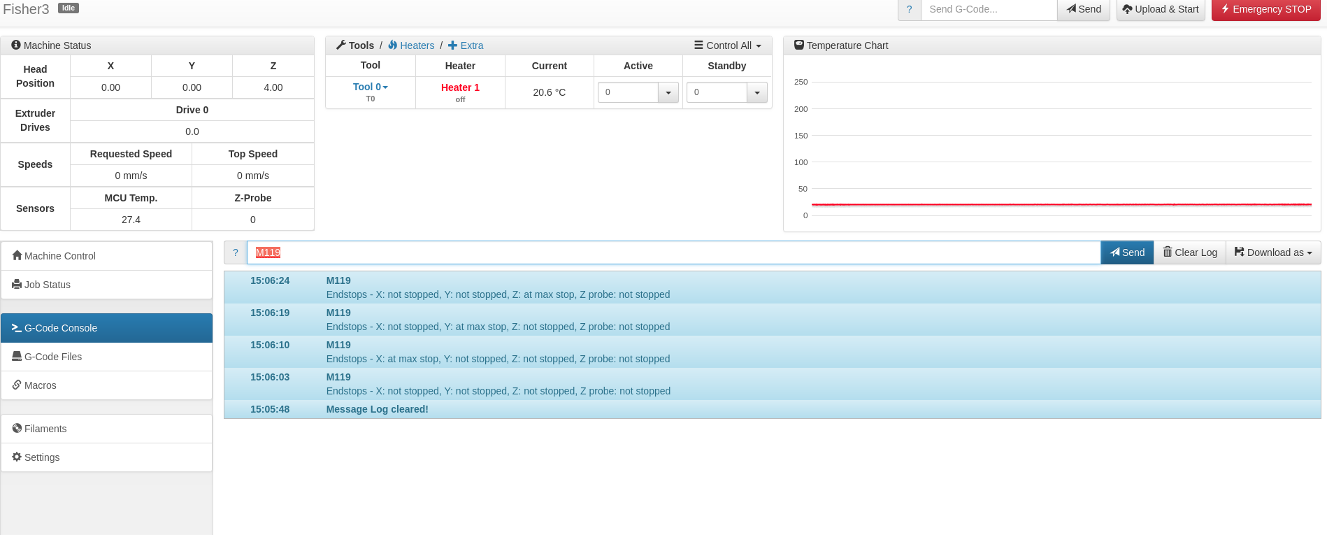
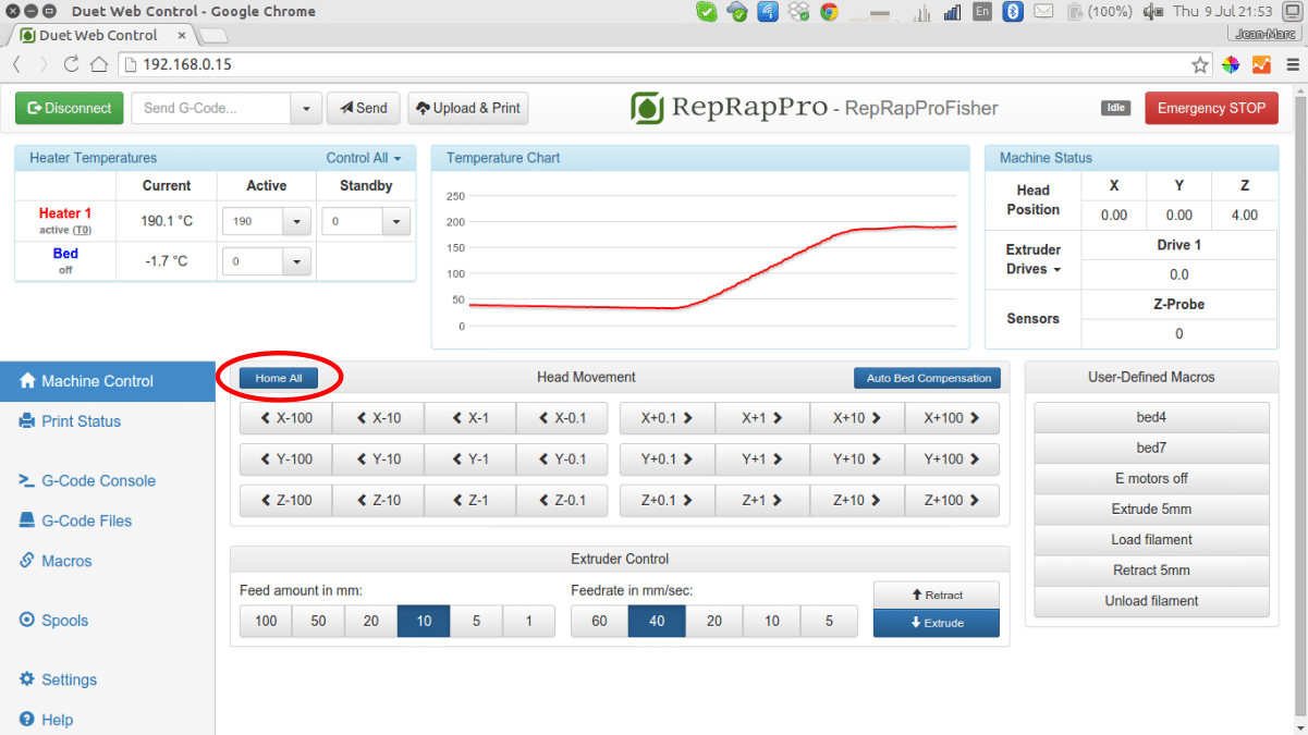
| Navigate to the Machine Control tab, and click on the ‘Home All’ button (or send G28). All axes will move up until they reach the endstops, down a little and back up again slowly, then move rapidly down to rest above the print surface.
The nozzle needs to be about 4mm above the surface, but the first time you do this it will be too high (deliberately, to prevent it crashing into the bed). The head position reading for Z should say 4.0. |
 |
| Send the command:
G92 Z0 This will zero the Z value. Then send the command: M208 S1 Z-50 This will allow the Z movement to go down to -50 (which should be plenty). |
|
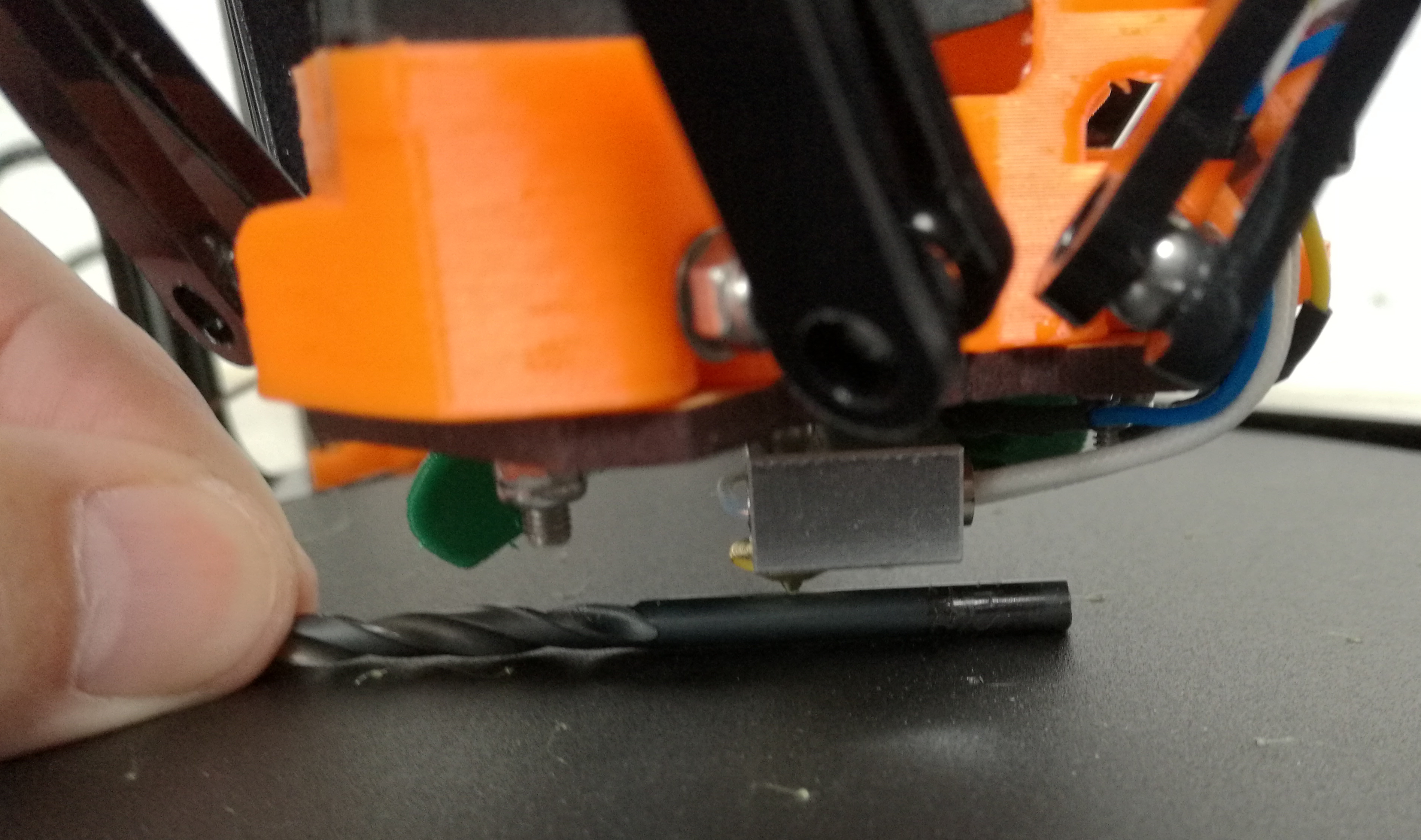
| On the Machine Control tab using the Head Movement jog buttons for Z carefully move the hot end and effector until it is about 4mm above the bed’s surface. If you have a 4mm drill bit, rolling the shank under the nozzle will give you an idea when you are in the right place.
Note the Z reading (which should be negative). Suppose it is -17. |
|
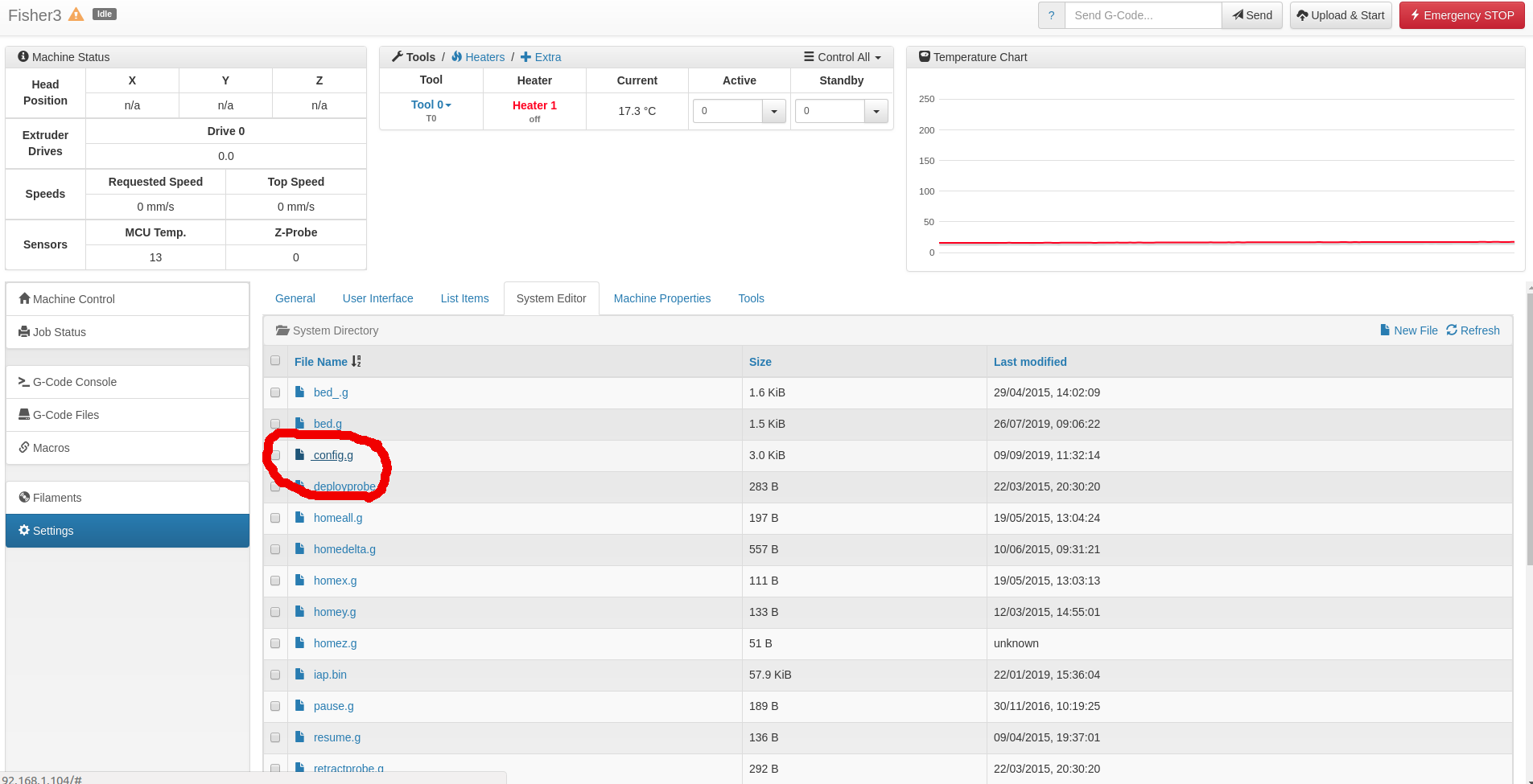
| Go to the Settings tab > System Editor tab and click on the config.g file to edit it.
Find these lines: ;*** The homed height (H150) is deliberately set too high in the following – you will adjust it during calibration Change the H value to subtract the negative value you just found: 150 -> 150 -(-17) -> 167. So in this case the line becomes M665 R81.0 L160.0 B75 H167 Save the file and reboot the Duet when asked. |
 |
| Now home all the axes again (Home All button on Machine Control tab or G28). The nozzle should now end up about 4mm above the bed. | |
| Take the bed out to prevent any oil getting on it (any oil or grease will prevent prints sticking to the bed).
Smear a little light machine oil (such as 3-in-1) up the six rods that form the towers above the linear bearings to the top. Do not use too much. Home the axes half a dozen times or so to distribute the oil evenly. Remove any excess oil from the tops of the bearings with a tissue. Put the bed back. |
Bed Probe Switches
Fisher knows where its bed is because of the three electrical contacts at the bed’s corners. If it gently pushes the hot end down anywhere on the bed one or more of these contacts is broken, and the Duet detects this if it needs to.
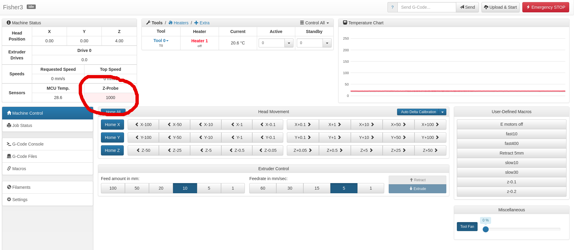
| Monitor the value under Z Probe in the machine status box. The value should be zero. You can also send G31 to get the current reading from the bed probing. Gently push down then release the bed near each of the mounting points in turn, and confirm the probe value changes to 1000, then returns to zero each time.
|
 |
Extruder Drive
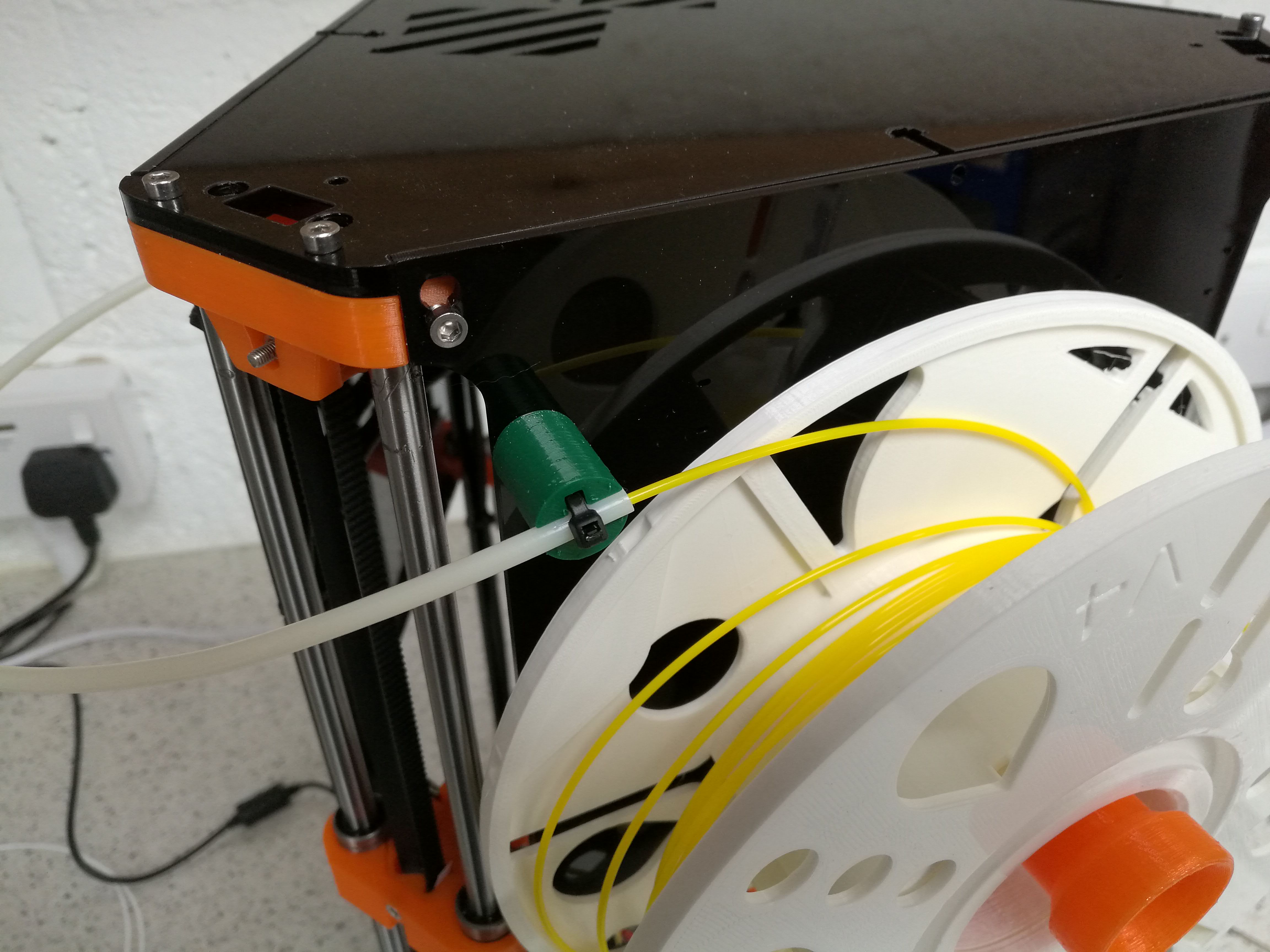
| Put the refill reel of PLA filament supplied on the MasterSpool. Line up the ties with the three slots on the MasterSpool. Release a short length of the end of the filament and push it into one of the filament retaining slots in the circumference of the rim (arrowed). Cut and remove the ties. Mount the MasterSpool on your Fisher with the free filament end pointing towards the PTFE tube through which it is fed to the extruder drive. | 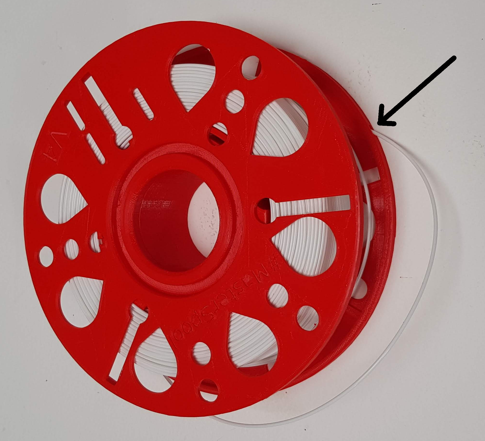 |
| Cut the end of the filament at an angle with side cutters (or scissors, at a pinch) so that it comes to a point, and is not flat-ended. Always do this with new filament, or when cleaning the end of filament that has been withdrawn from the machine and is now being re-inserted.
Push some filament through the filament guide tube, which should feed it into the extruder drive block until it hits the hobbed drive.
|
 |
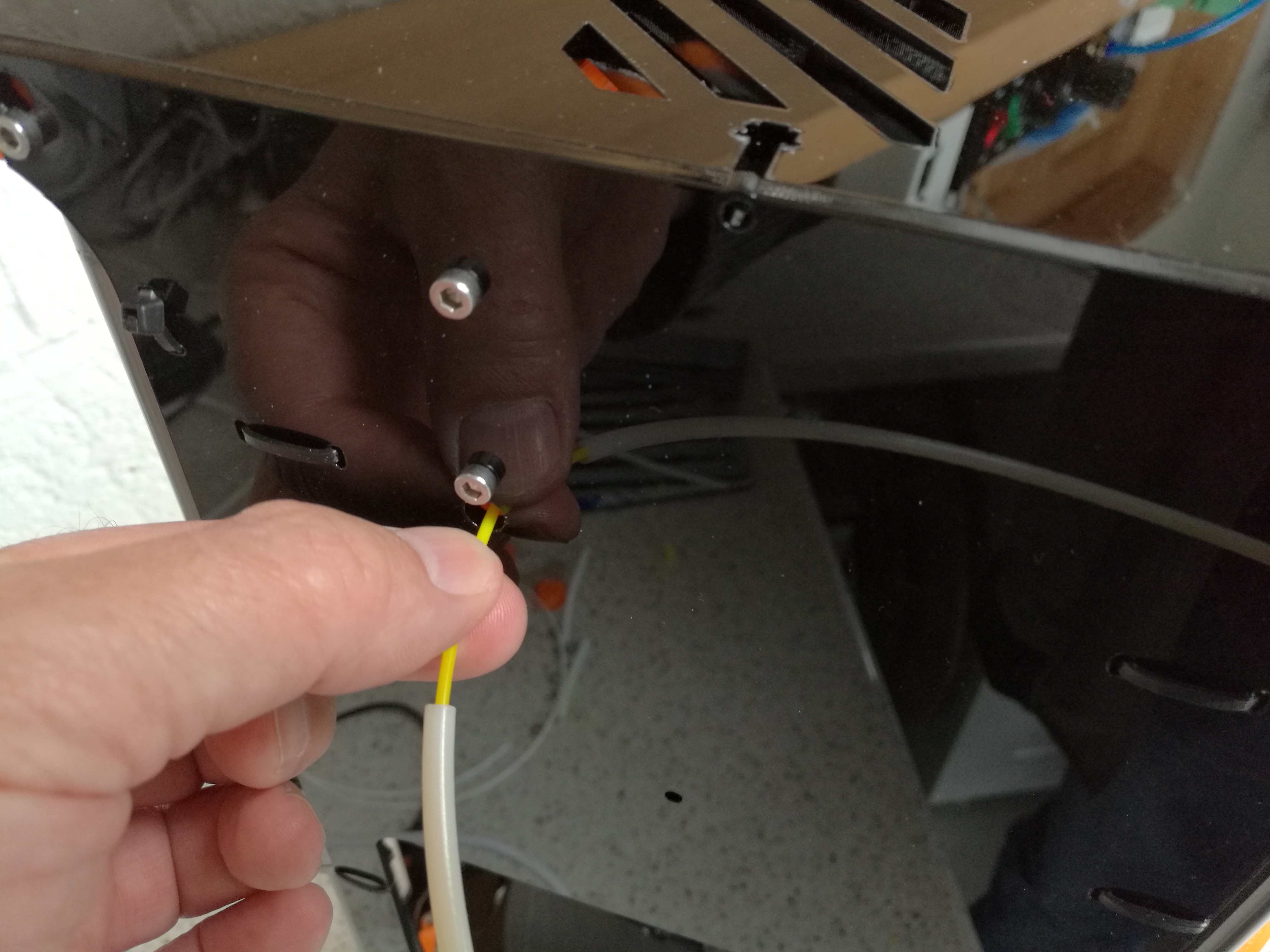
| You may find the next step easier with the filament guide tube removed from the extruder drive as shown in the photo. Also it may be easier if you remove the top panel of the machine.
Using the thumb wheel (you’ll have to reach up inside), engage the filament and feed a few centimetres through. Hold the thumb-wheel and try to pull the filament back out. If it slips easily, adjust the idler tension using the M4 button head screw in the extruder drive. If you removed it, return the filament guide to its hole. |
 |
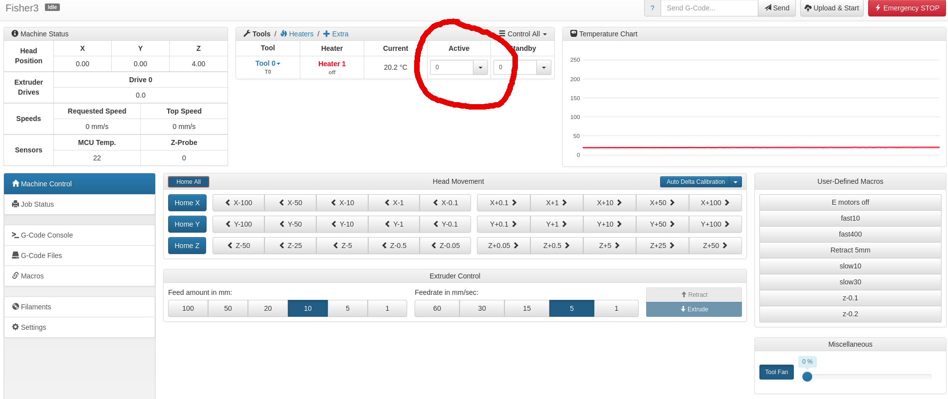
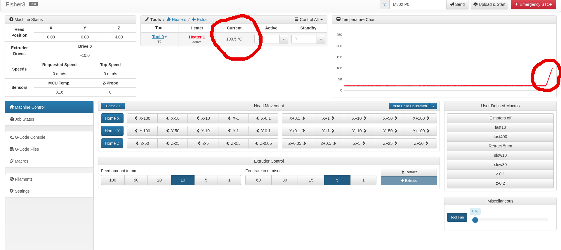
| In the Machine Control tab enter a value of zero as the Heater 1 Active temperature.
As the nozzle is still at room temperature, cold extrusion prevention must be overridden. Send the following G-Code: then send: T0 selects tool 0 (Fisher has only one tool – its extruder drive plus its hot end – and T0 is it). The M302 P1 command overrides the normal prohibition on trying to extrude filament when the hot end is cold.
|
 |
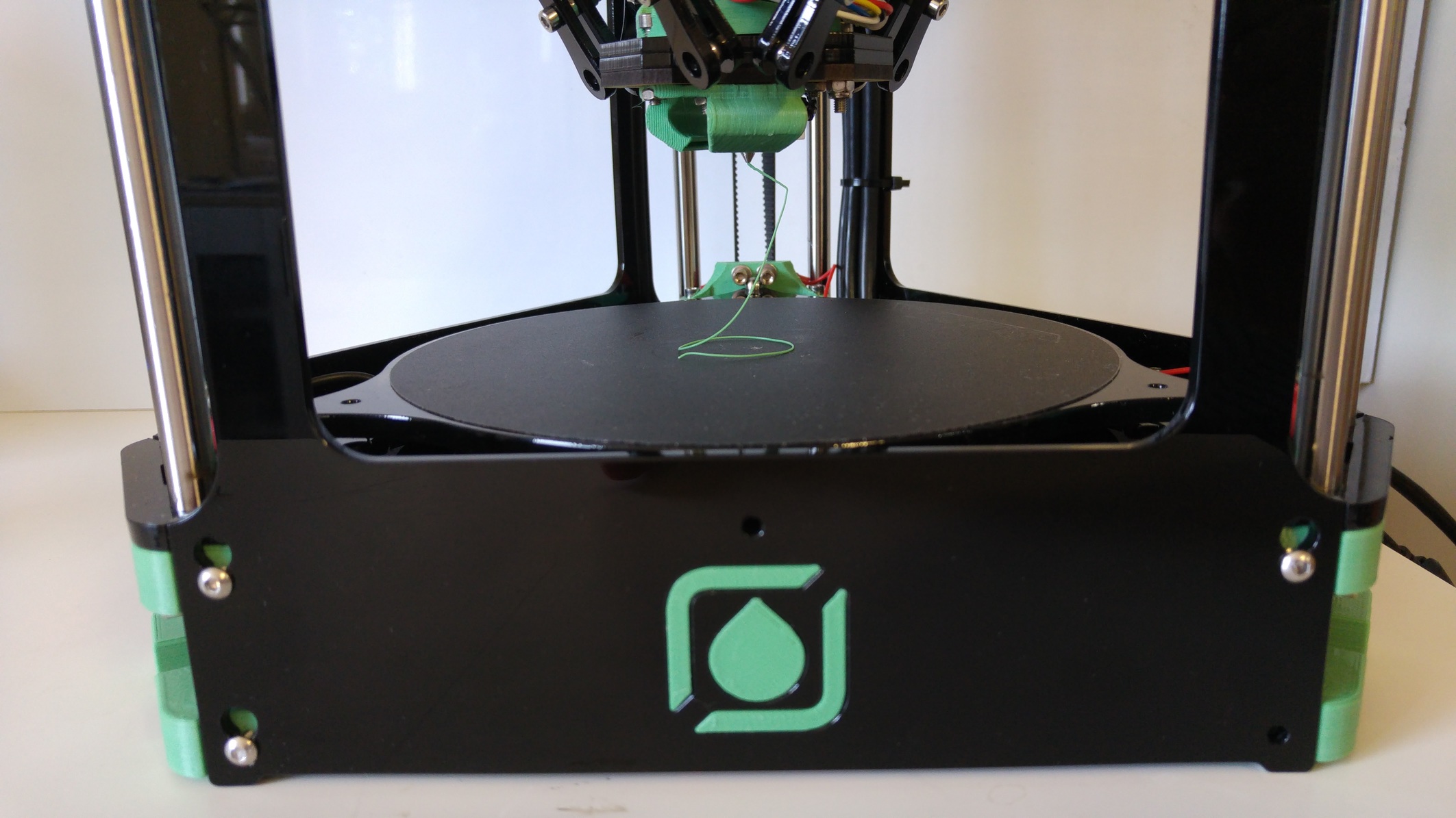
| Now advance the filament using the extrude button on the Machine Control tab, until it reaches the top of the heatsink. You should be able to see its end through the translucent tube (sometimes, in a bright room, a small torch helps). | 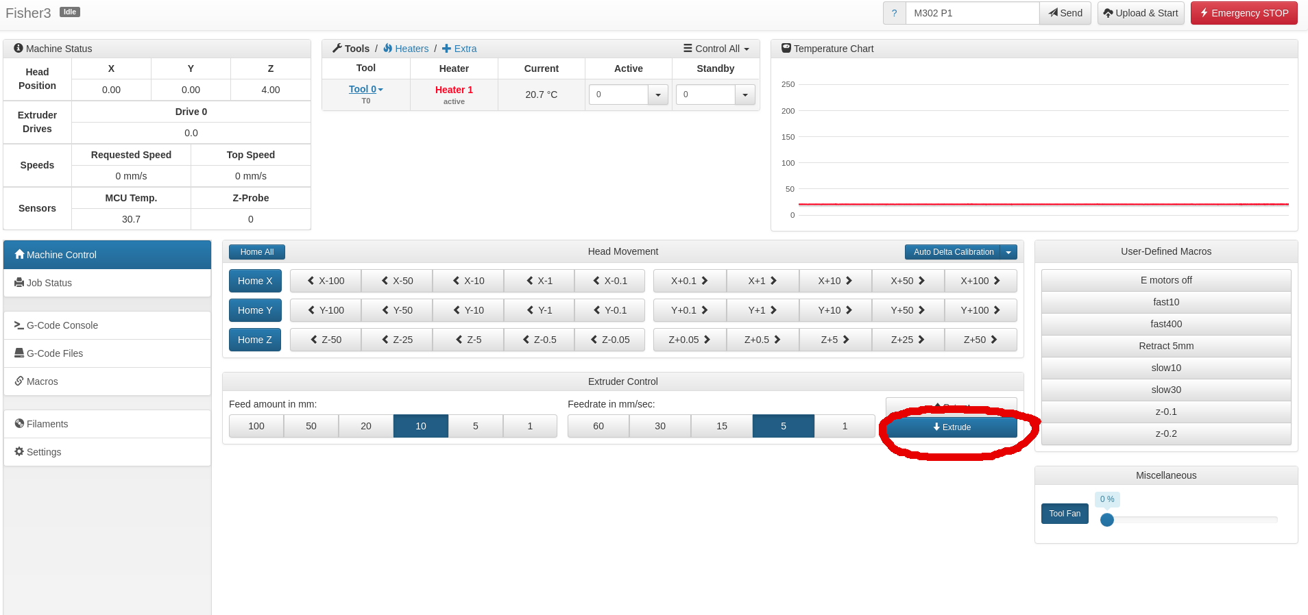 |
| Once satisfied the extruder drive is working, re-enable cold extrusion prevention using the following command:
|
 |
Hot End
| Once the temperature of the nozzle has reached 200 oC filament can be extruded. | 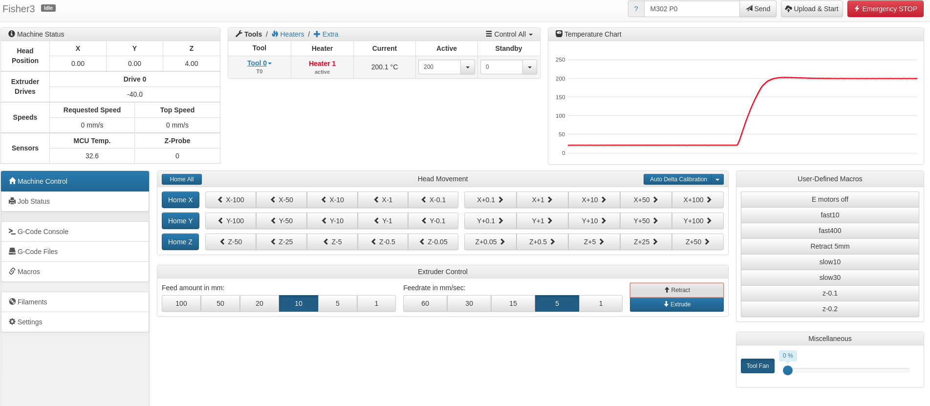 |
| The next step is to check extrusion. The extruder drive motor will be enabled, so send the following command to put it into an idle state: M84 E0 Or click on E motors off macro button.Using the thumbwheel, feed the filament into the hot end and extrude a couple of centimetres. With a steady feed, the filament should extrude without too much resistance. Back off the filament from the nozzle by 3 or 4 mm.If you removed the top panel above, replace it. |
|
Bed Probing
With the hot-end still at 200 oC click on Home All (or send ‘G28‘). Check the Z Probe value. This should be 0. If it isn’t one or more of the three bed corner contacts is not seated properly on its two cylinders. Tap the corners of the bed to re-seat it until Z Probe goes to 0. Take great care not to touch the hot end. |
 |
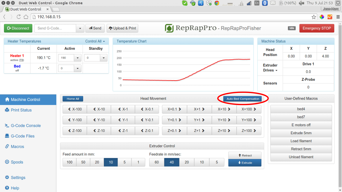
Click on Auto Delta Compensation (or send ‘G32‘). Before printing always do this when the hot end is hot.
The file sys/bed.g will be executed. That will probe the bed in a grid and record a map of its surface. If you do it when the hot end is cold any small pieces of filament stuck to the nozzle will cause the compensation to be inaccurate. When the head is hot, those plastic pieces are molten and just move out of the way as the bed is probed. |
 |
| The Duet firmware will display a map of the bed like this, which you can zoom and rotate with the mouse. It looks a bit alarming, but the vertical scale is exaggerated, of course. As you can see, this bed had an overall slope, and was also not quite a flat plane. Both of these are normal, and the firmware will use this information to print at right-angles to the bed and to compensate for any slight irregularities in it.
|
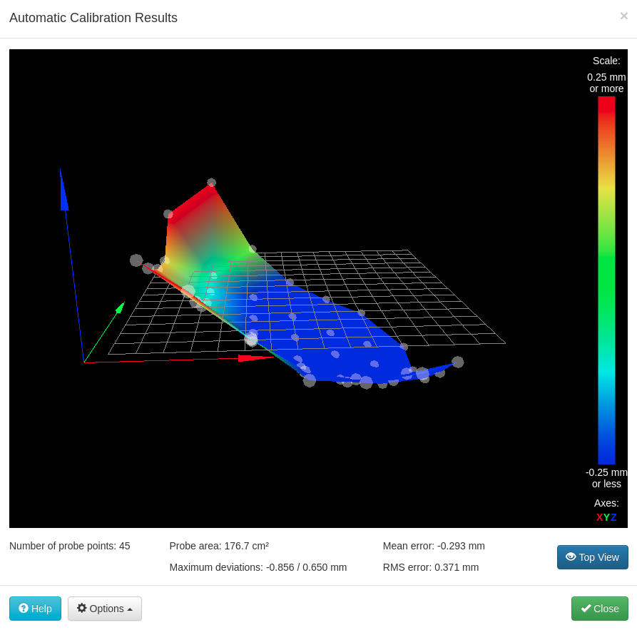 |
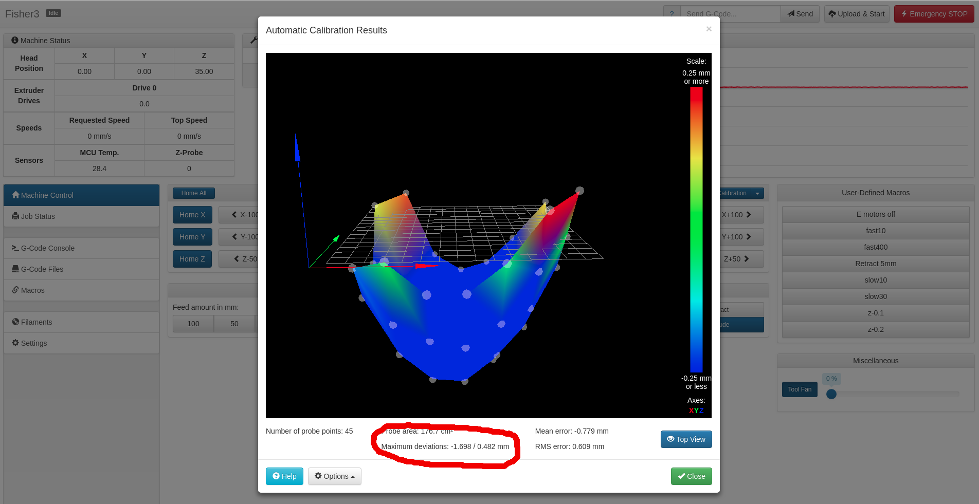
| If your bed map looks these pictures and the maximum deviations are under 2mm then move on to the bed probe offset section below. But if there is a bigger overall slope, or if the maximum deviations are over 2mm this will need to be corrected by editing the endstop adjustments in your config.g file. |
|
|
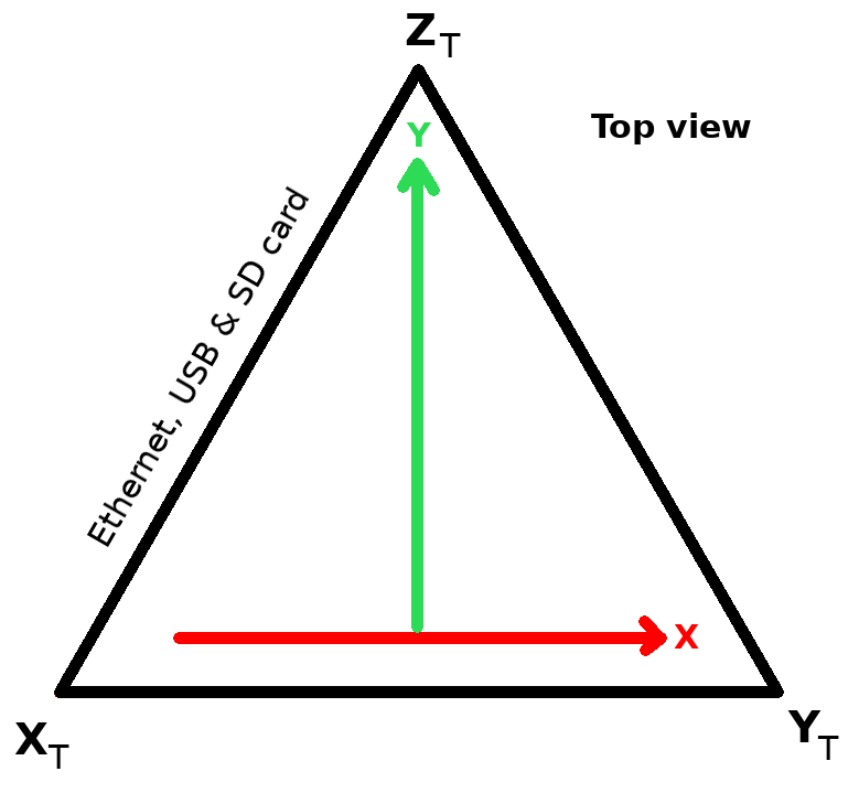
Rotate the map with the mouse so you can see the coloured axis arrows (X, Y and Z) for the X, Y and Z movements when printing marked on it. Make a note of where the map is high or low relative to the towers in the diagram on the right which is a plan view of the machine from above. The towers are labelled XT, YT, and ZT. The printing X and Y axes are also shown; these correspond with the X and Y axes in the previous picture. (We know this double use of X etc is slightly confusing, but the Duet has to control Cartesian RepRaps as well as delta ones like Fisher.) Close the map window. Click on ‘Heater 1’ to put it in standby mode. At around 120oC clean any solidifying plastic off the nozzle with tweezers. This is important for both this and the next sections, and the rest of this section can be done with the hot end cold. Go to the Settings > System Editor tab and click on the config.g file to edit it. Find these lines (near the end of the file):
The X, Y and Z values are offsets for the points on each tower, XT, YT, and ZT where the endstop switches trigger. These are repeatable, but not always equal. Change the X, Y, and Z values to raise or lower the surface according to the note you made. So, for example, if the map was too high by the XT tower, change the line to:
and so on. Adjustments of 1 or 2 millimetres should work fine. Save the file and reboot your Duet when asked. Click on the ‘Home All’, then ‘Auto Bed Compensation’ to give you a new map. It should be improved, but you will probably have to iterate this process two or three times to get things right. As mentioned in the previous section, the bed doesn’t have to be competely flat. The compensation is effective even when it isn’t. |
 |
Bed Probe Offset
Next we need to allow for the slight compression of the rods when the bed is probed. (This doesn’t happen when printing, which is a near-zero force process.)
| Send:
M208 S1 Z-50 followed by:
This will move the nozzle to about 2mm above the centre of the bed. But it may not be exactly 2mm – the elasticity of the machine means that, when the bed probing triggers the bed contacts, that may not correspond exactly to the point Z=0. However, this elasticity is repeatable, and so can be compensated for. Using the Z-0.05 jog button move the nozzle down until it just touches the bed. Use a magnifying glass if you have to. Note the Z coordinate that the machine thinks it is at. Suppose it is A mm. Clearly we want this to be 0. Navigate to the Settings tab -> System Editor and select the file config.g to edit. Find the line near the end that says:
The Z value sets the height at which the bed contacts are considered to trigger. Change this value to -A. So if A were 0.35mm the line would become:
Save the file. The firmware will ask you if you want to reboot. Say yes. (If you didn’t do the endstop adjustment above, this will also turn off the hot end heater. If you did, it will already be off.) |
|
| If the hot end was hot, as it cools remove any filament from the tip with tweezers. You will find that around 120 oC the filament is still soft enough to remove, but sufficiently coherent to all pull away at once. This is a good way to remove random bits of filament from around the nozzle. Make sure the nozzle is clean when it gets to room temperature.
If it was cold, you should have already done this. |
Prepare for Printing
Your RepRap Fisher 3D printer is now almost ready for its first print. Check the following before proceeding…
Filament spool is loaded. Threaded balls are locked. Belts are equally tensioned. Top panel is fitted. Print bed is in place.
Back – Bed, Top Plate and Belts Next – Printing