
Build Instructions – Base Assembly – Tower Assembly – Panels and Rods – Effector Assembly – Extruder Drive
Hot End Assembly – Electronics – Bed, Top Plate and Belts – Commissioning – Printing – Troubleshooting
Goal
By the end of this section, you will have assembled the print bed, put the rest of the covers on the machine, and added the drive belts and filament spool holder.
Bed Assembly
You will need the following parts:
| # | Component | Qty | Type | |
| 1287 | Bed | 1 | Laser cut |
|
| 1137 | M3x8mm button head screw | 3 | Hardware | |
| 1298 | Bed Spacer | 3 | Laser cut bag | |
| 1262 | Buildtak Dia 165mm | 1 | Hardware |
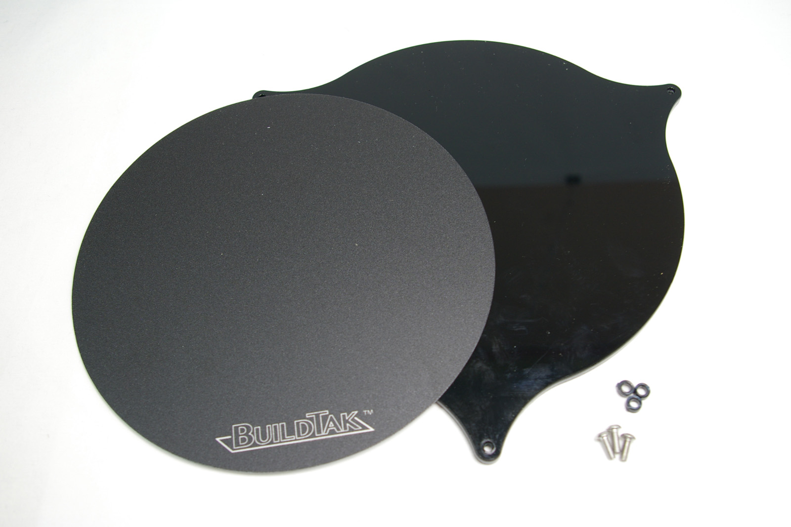
| Remove the protective film from the acrylic. | 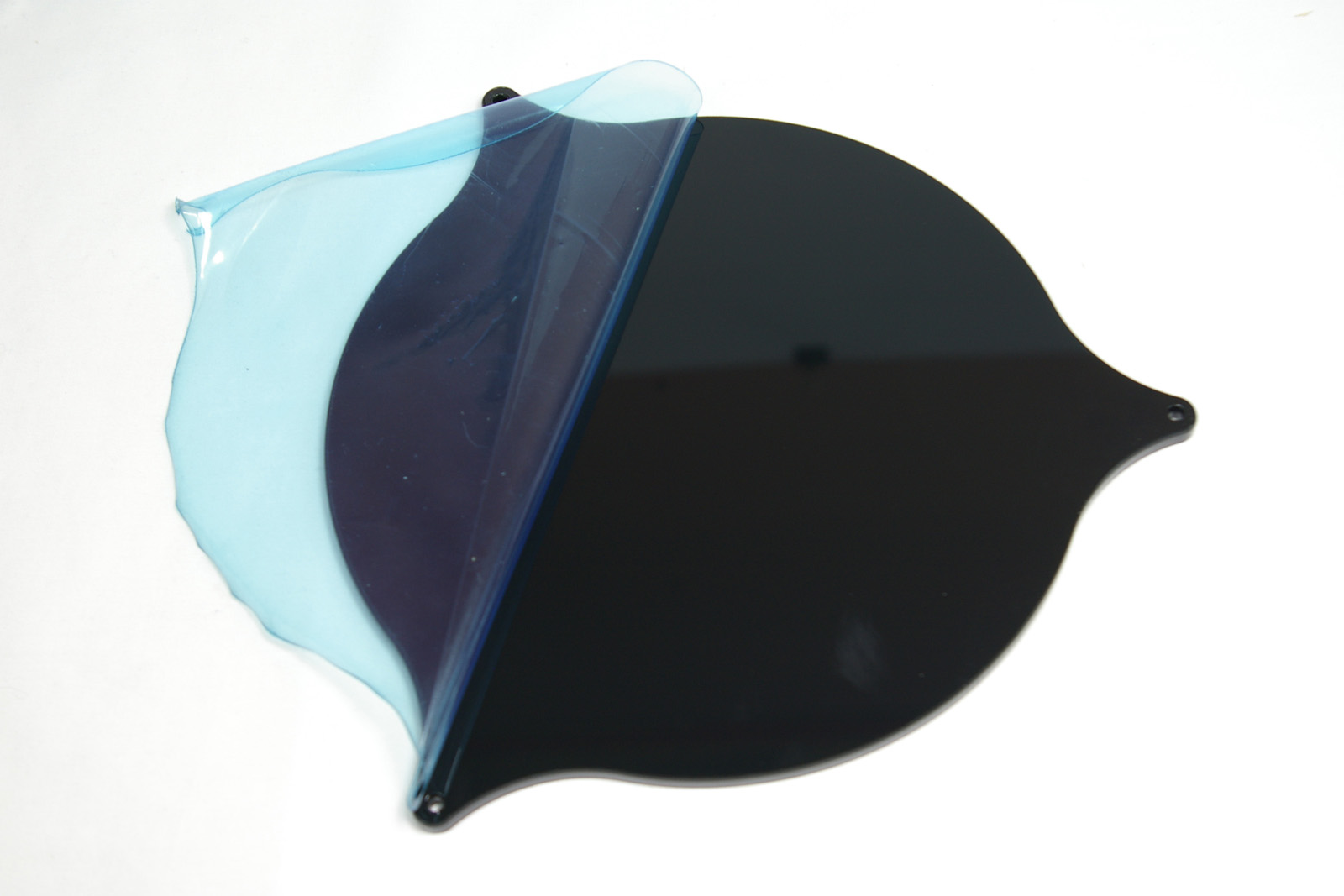 |
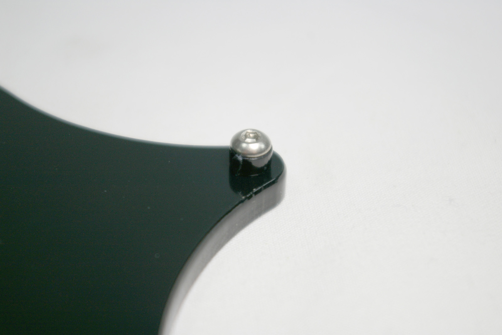
| Screw an M3x8mm button head screw through the bed spacer and self-tap into the acrylic bed. Repeat on the other two corners. |
|
| Remove the backing from the BuildTak sheet. The adhesive is quite strong. You may find it easiest to start peeling with a pair of tweezers. | 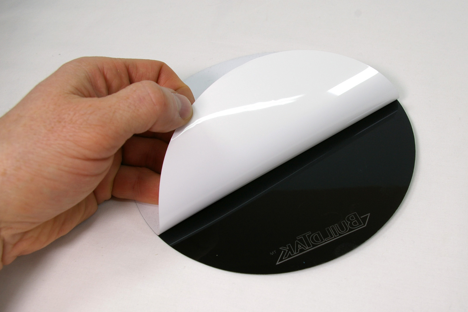 |
| The BuildTak is 165mm in diameter, the bed is 170mm in diameter, so start 2.5mm (or thereabouts) from the edge. Stick down one edge, then work across the bed, pushing the BuildTak sheet down as you go. This will stop air bubbles getting stuck under the BuildTak. | 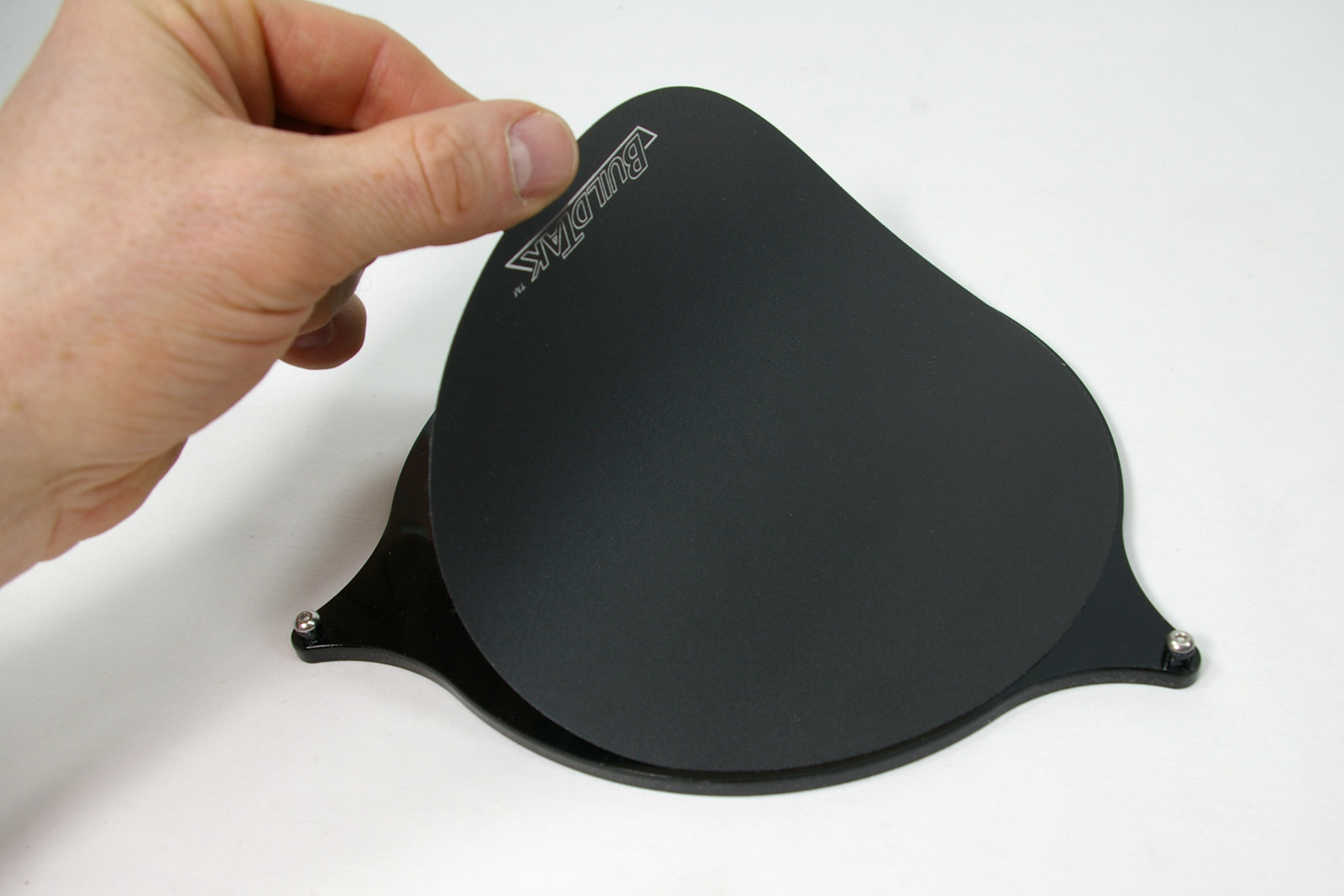 |
| The finished bed. | 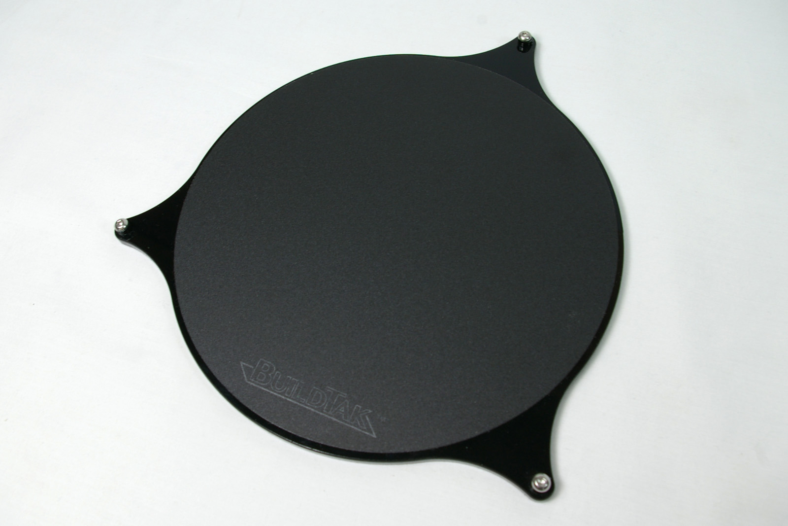 |
Fitting the Bed
You will need the following parts:
| # | Component | Qty | Type | |
| Bed | 1 | Assembled | 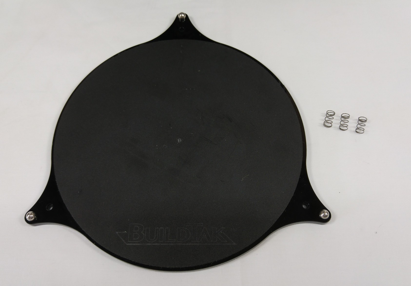 |
|
| 1251 | Bed Spring | 3 | Hardware |
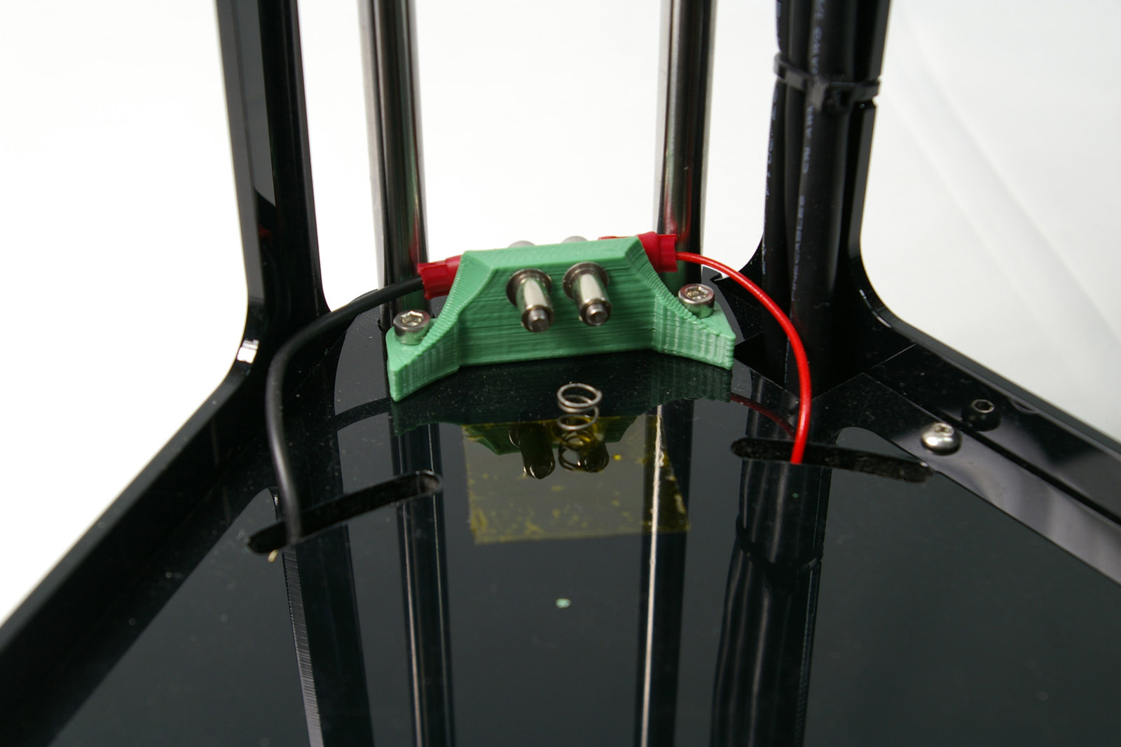
| Place a spring into each hole near the kinematic mounts. Hold them in place with a piece of tape. Put it over the hole, through the coils of the spring. This will stop the spring pinging out and disappearing when you remove the bed! |
|
| Drop the bed onto the springs with the button-head screws rotated a bit away from their electrical contacts. | 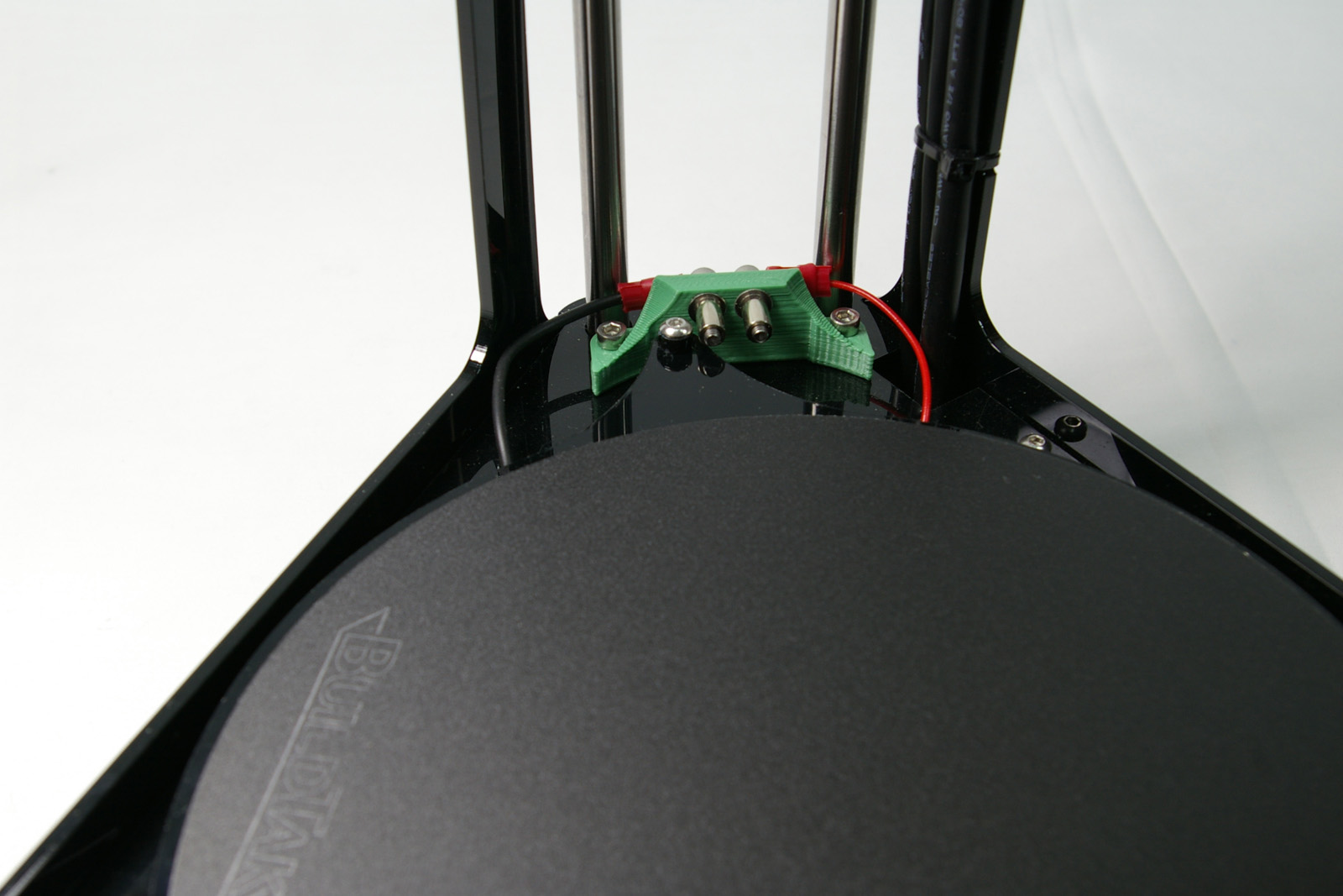 |
| Push the bed down and rotate, then release it allowing the springs to lift it into the spacers. Reverse the process for removal. | 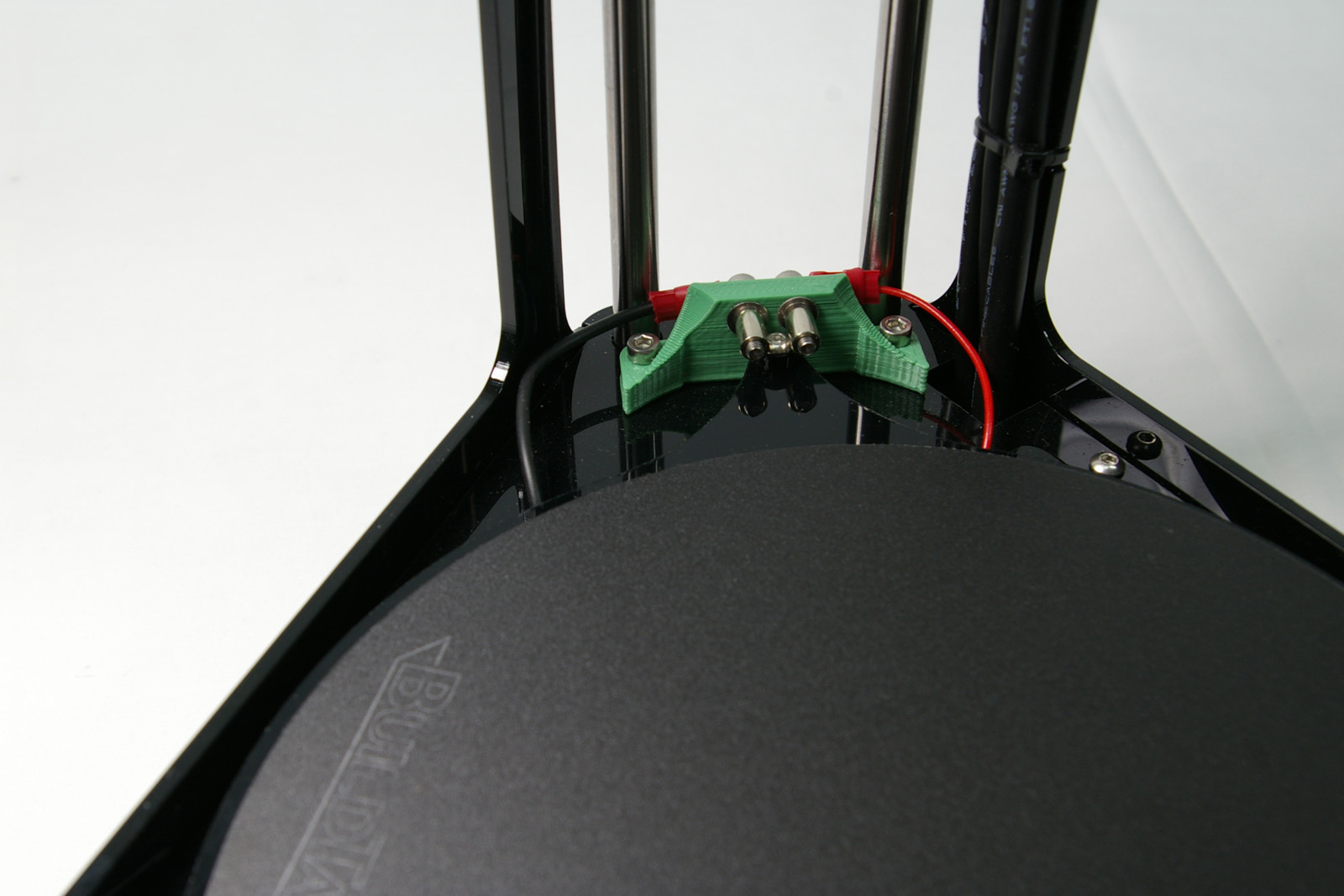 |
Spool Spigot
For RepRap Fishers shipped after 1 April 2019 (1178.2) you will already have fitted the MasterSpool spigot, so skip the rest of this section and go straight to Top Plate and Final Frame Fit below.
The spool spigot carries the spool on the side of the printer. You will need the following parts:
| # | Component | Qty | Type | |
| 1249 | Spigot | 1 | Printed | 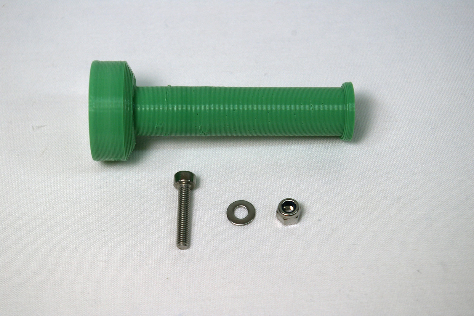 |
| 242 | M3x16mm cap head screw | 1 | Fastener | |
| 212 | M3 plain washer | 1 | Fastener | |
| 204 | M3 Nylock nut | 1 | Fastener |
| Drop the M3x16mm cap head screw into the spigot, and screw it through the end. | 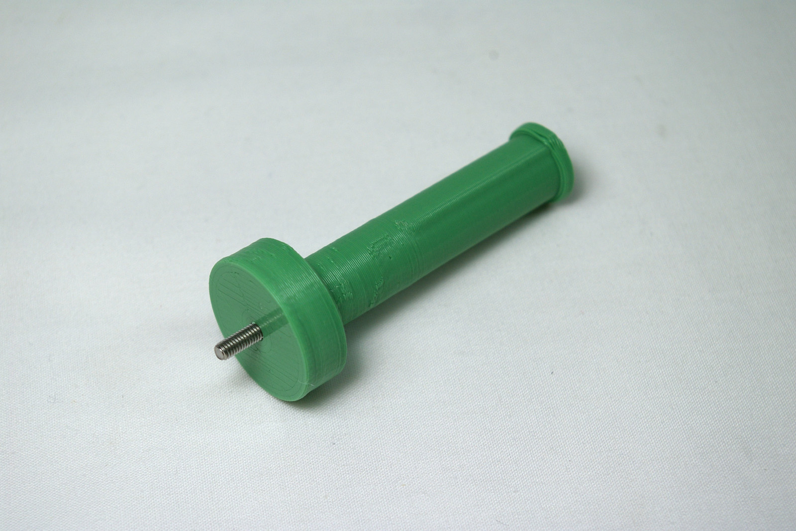 |
| Attach the spigot to the side panel through the hole under the extruder. Fasten with the M3 plain washer and M3 Nylock nut. | 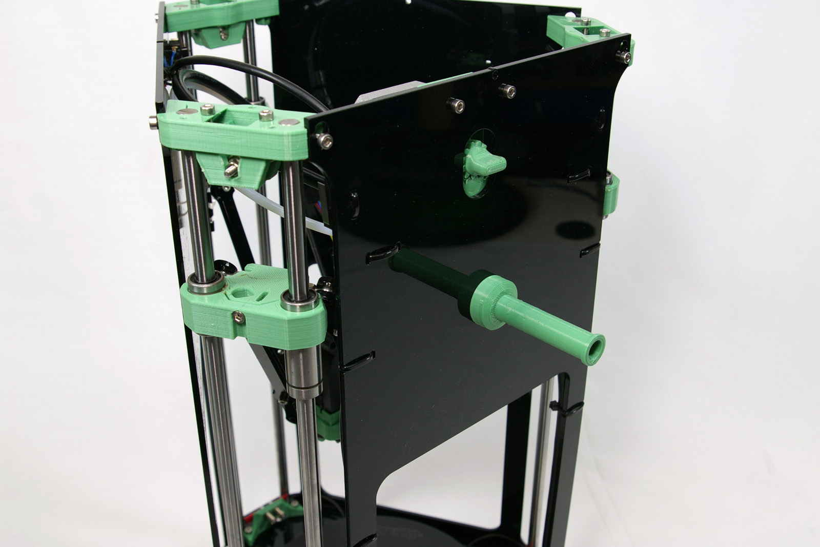 |
Top Plate and Final Frame Fit
You will need the following parts:
| # | Component | Qty | Type | |
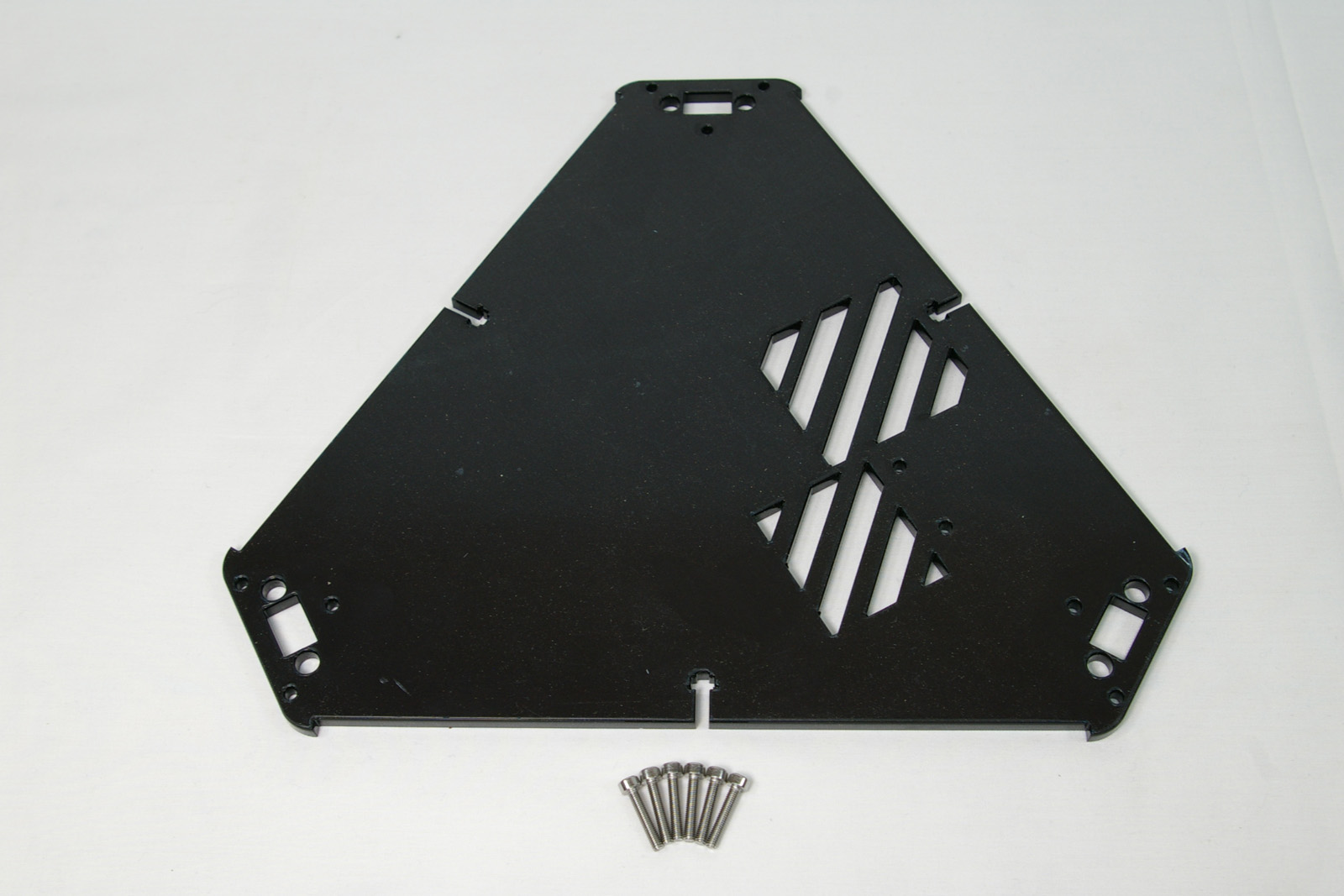
| 1284 | Top plate | 1 | Hardware |
|
| 242 | M3x16mm cap head screw | 6 | Fastener |
| Remove the protective cover from the acrylic top plate. | 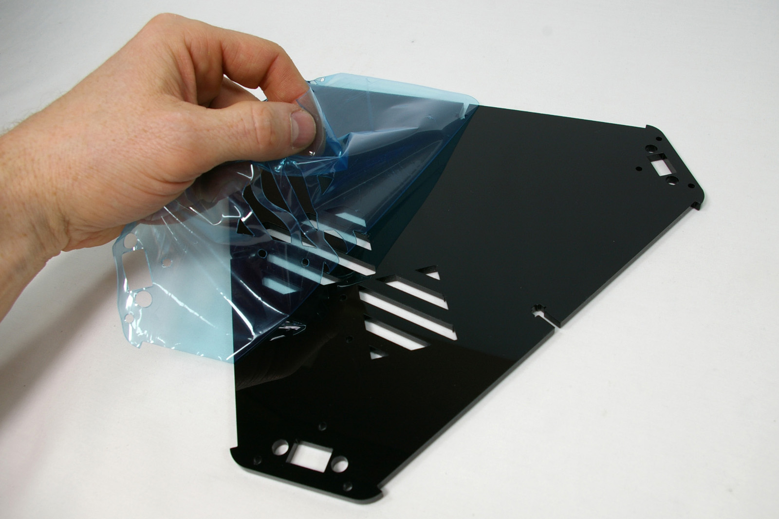 |
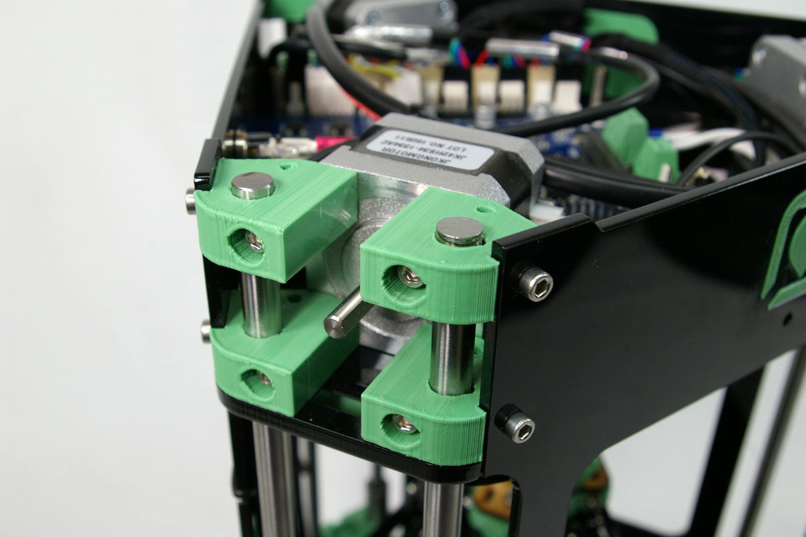
| Take the idler bearing assemblies that you set aside earlier and put them back in their holders (see also the next image). | 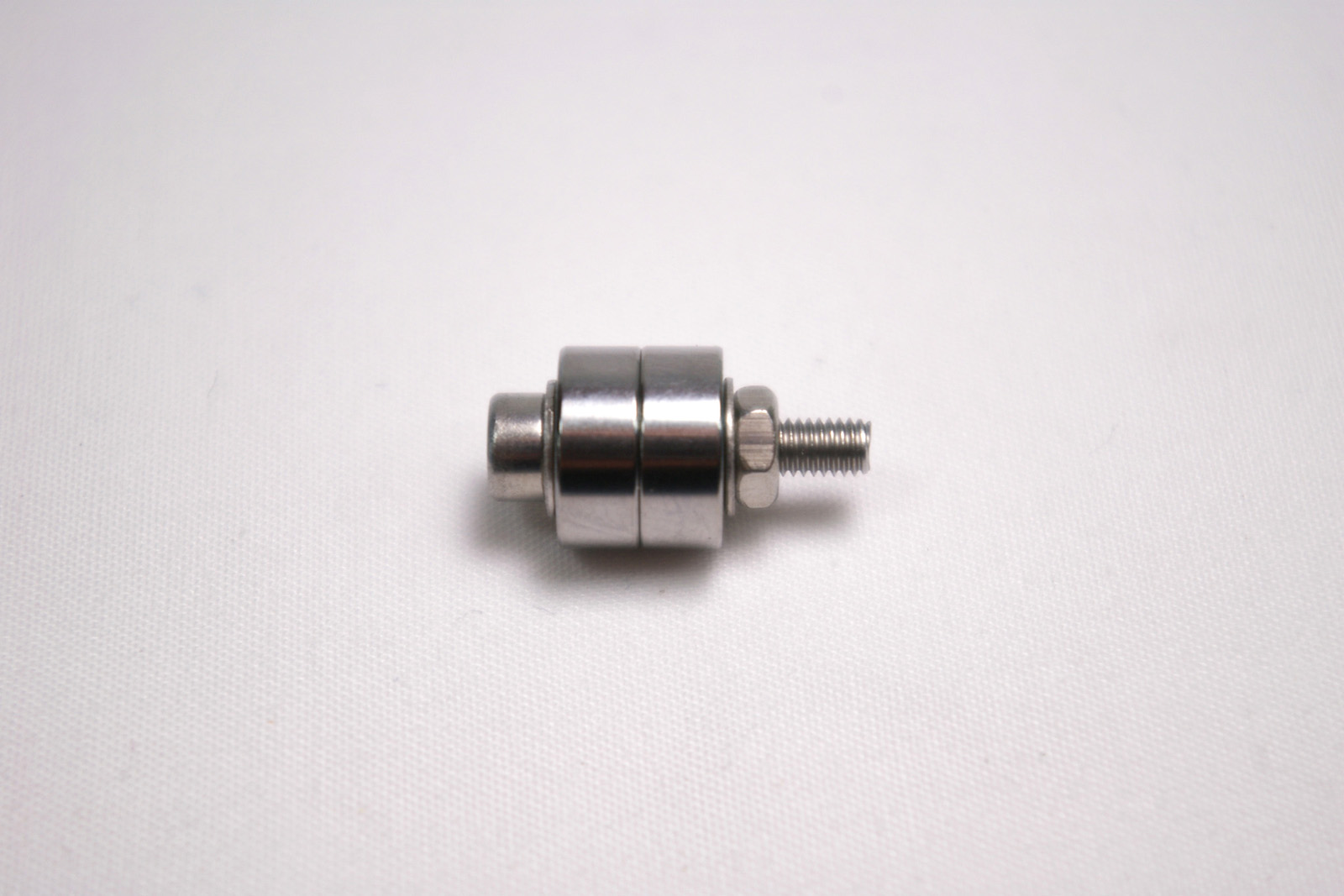 |
| First, make sure the rods are flush with the top of the idler. The top plate fits on top of this, stopping the idler sliding down the rods when the carriage belt is tightened. | 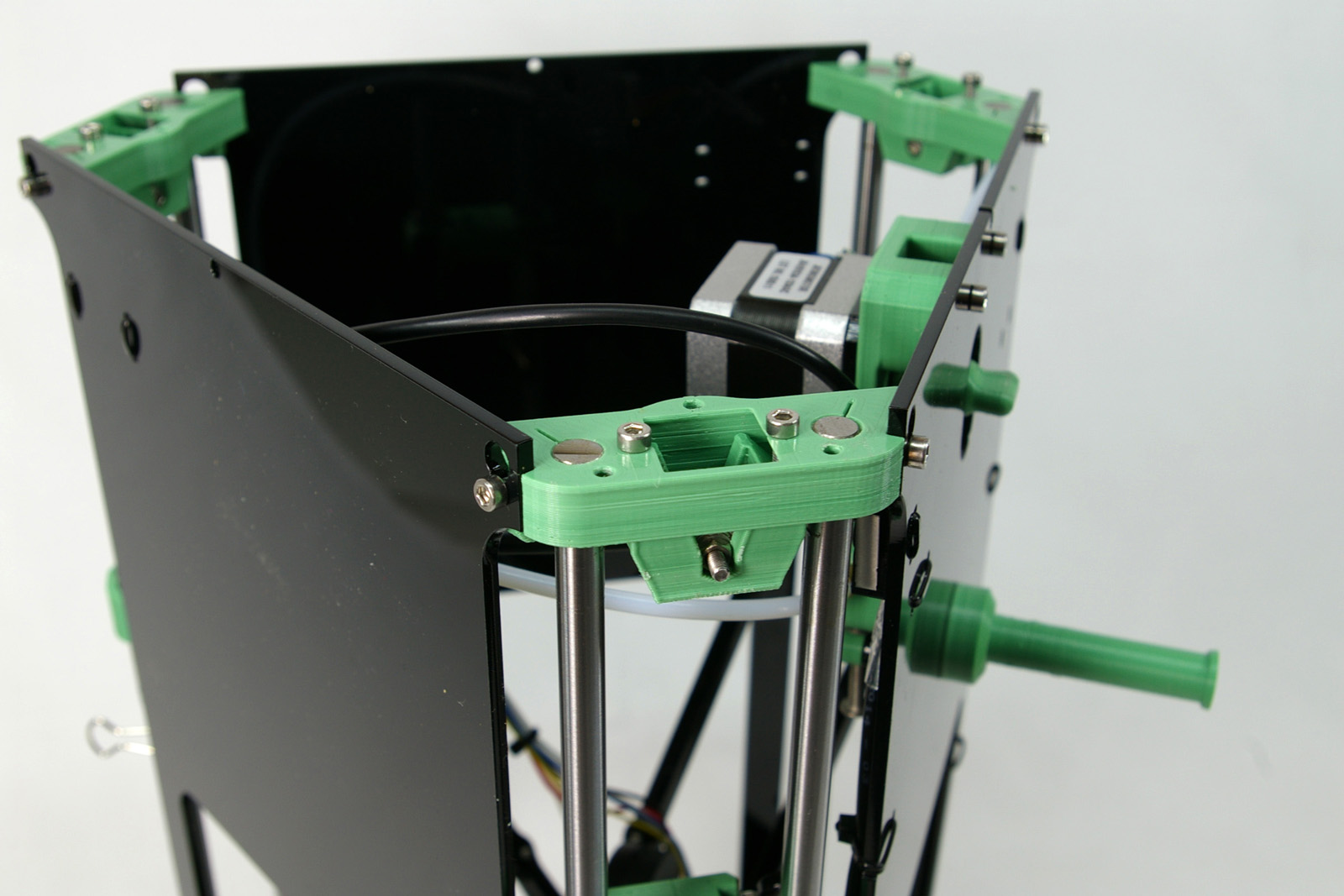 |
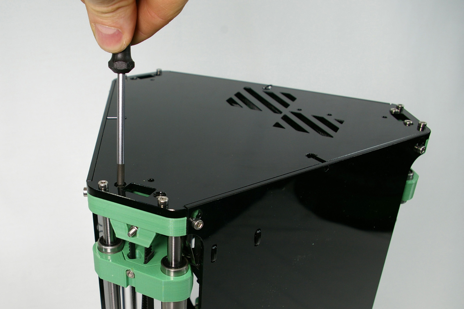
| Fit the top plate. Don’t screw it down just yet; you will need to adjust the side panels for their final fit. At the moment, the side panels will probably not be level with the top plate, and the screw that connects the side panel to the idler will not be fully engaged in the slot. | 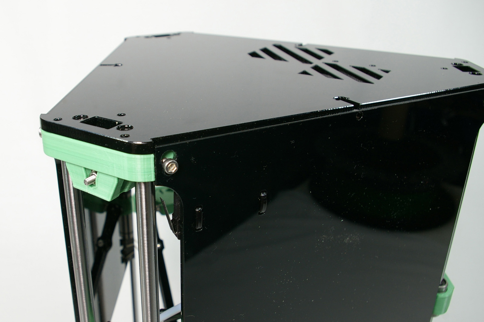 |
| Turn the printer upside down, so it’s resting on the top plate. Slacken all 12 motor mount screws (four at the bottom of each tower). | 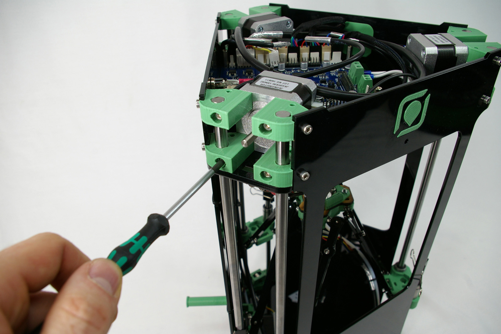 |
| Also slacken the six screws at the top of the side panels (two each on each panel, into the idler). | 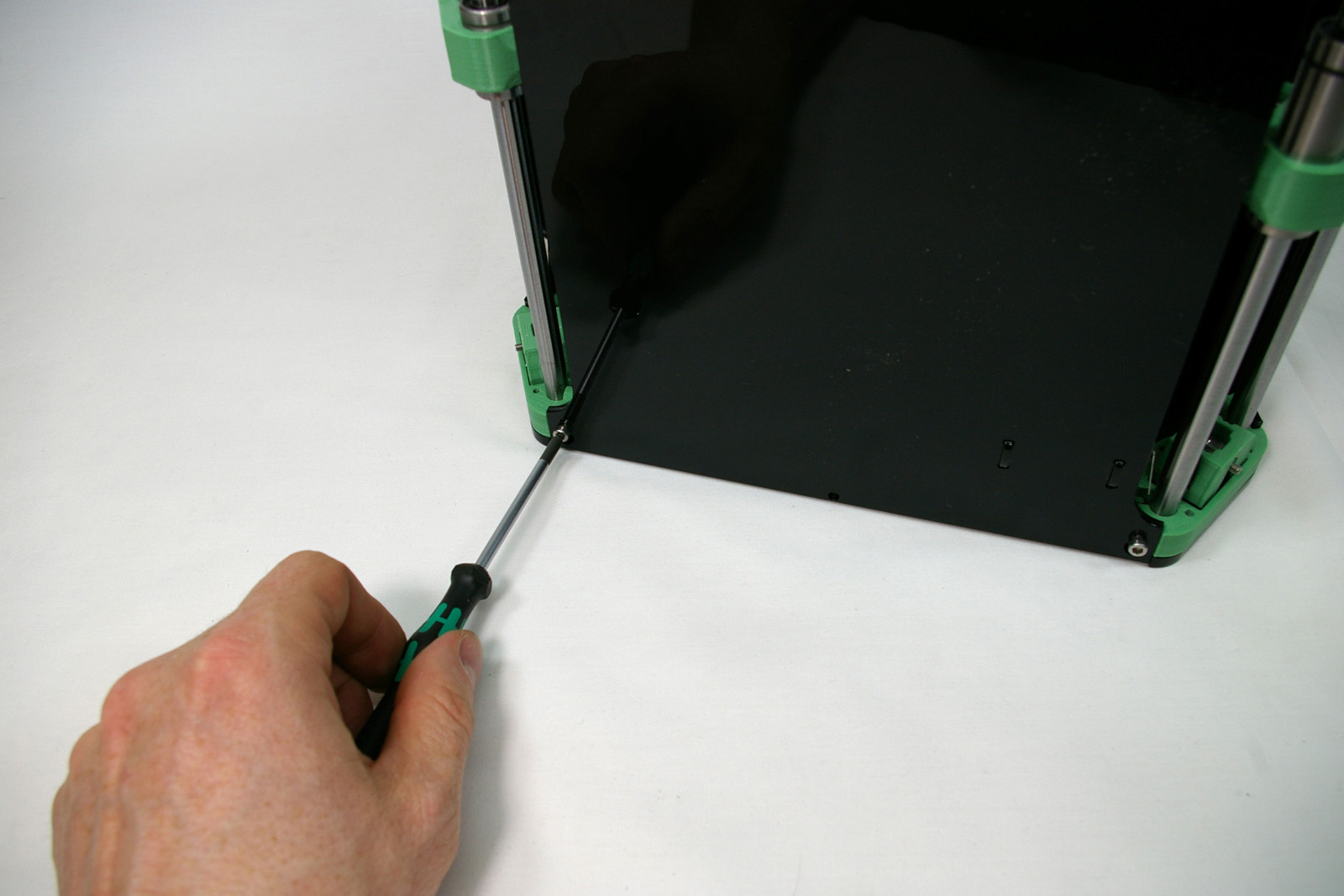 |
| Push gently but firmly down on each motor. The effect of this will be to push the motor down on the rods, until the side panel stops it. If you push too much, the side panel will start to bow. | 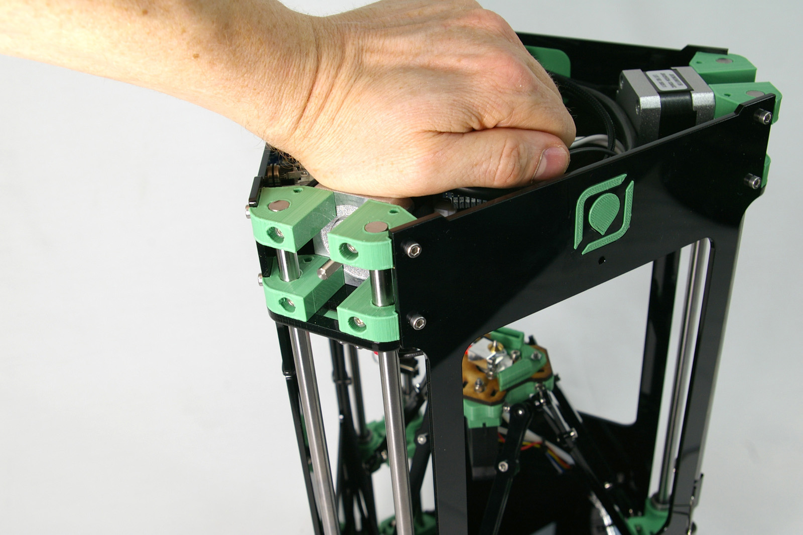 |
| The rods will probably poke out of the bottom of the motor mounts. Repeat on the other motors. |  |
| The end result should be that the side panels are flat against the surface, with the screw fully engaged in the slot. | 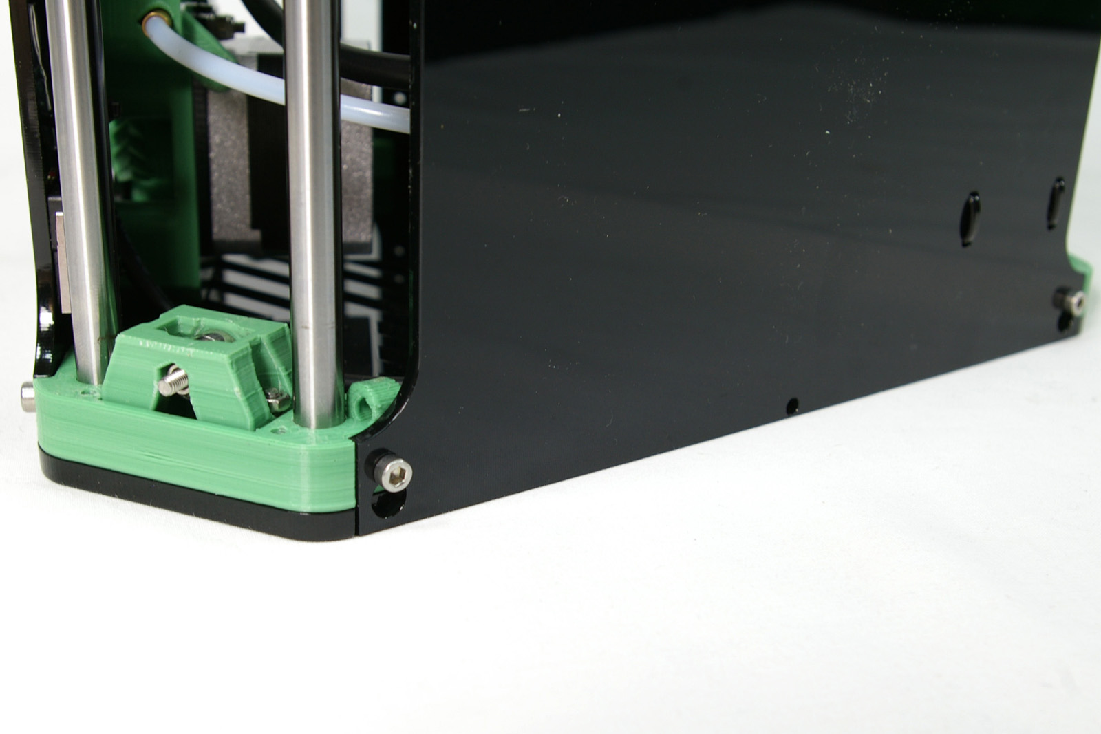 |
| Fully tighten the 12 motor screws. These clamp the rods at the bottom. |  |
| Tighten the six screws at the top of the side panels. This is easier to do with the printer upside down, as the M3 nut in the idler will not fall out. | |
| Turn the printer over, right way up. The top of the side panels should be flush with the top plate. Fit the top plate with the six M3x16 cap head screws into each idler. | 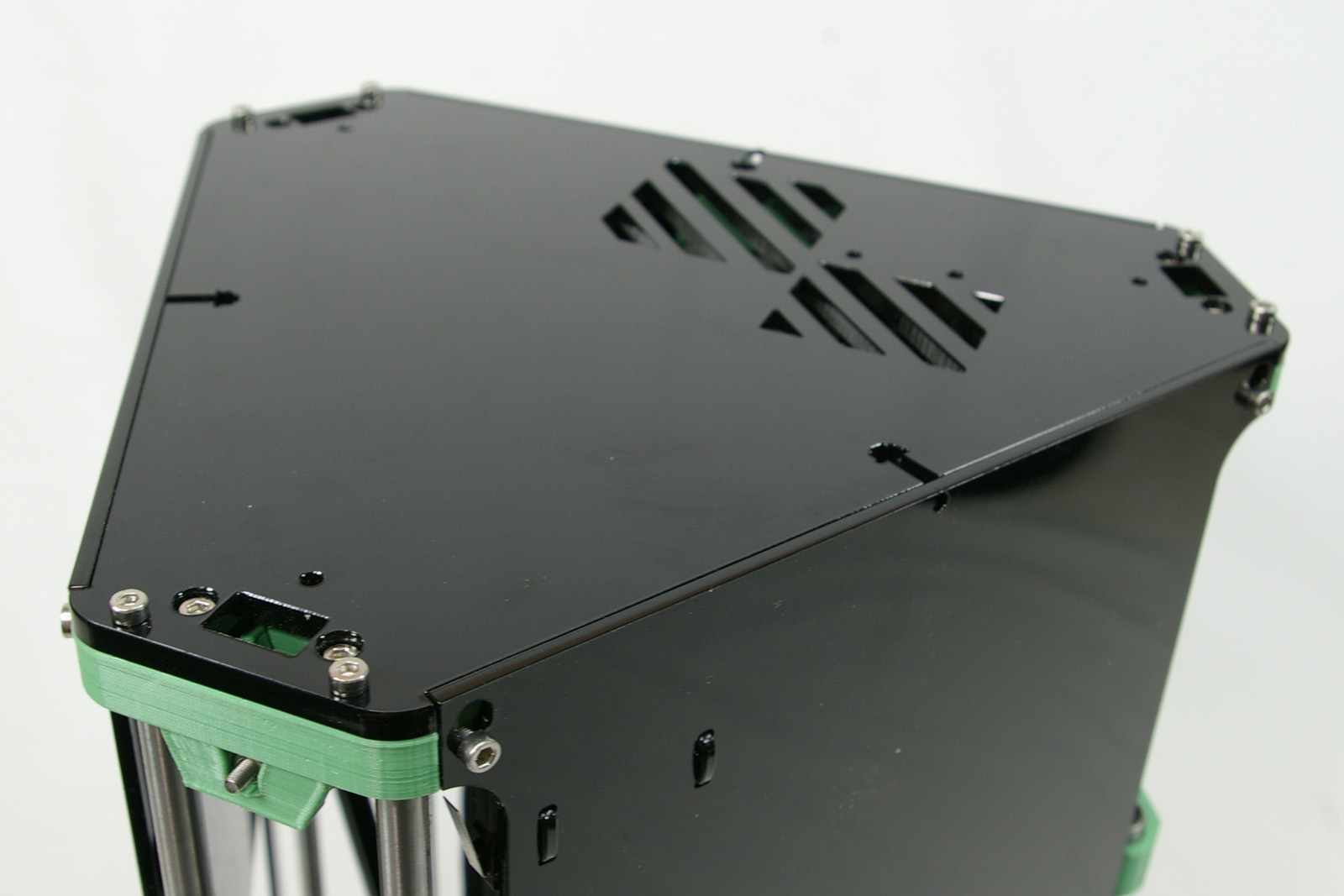 |
| For RepRap Fishers shipped before 1 April 2019 skip this step and go to Drive Pulleys and Belts below.
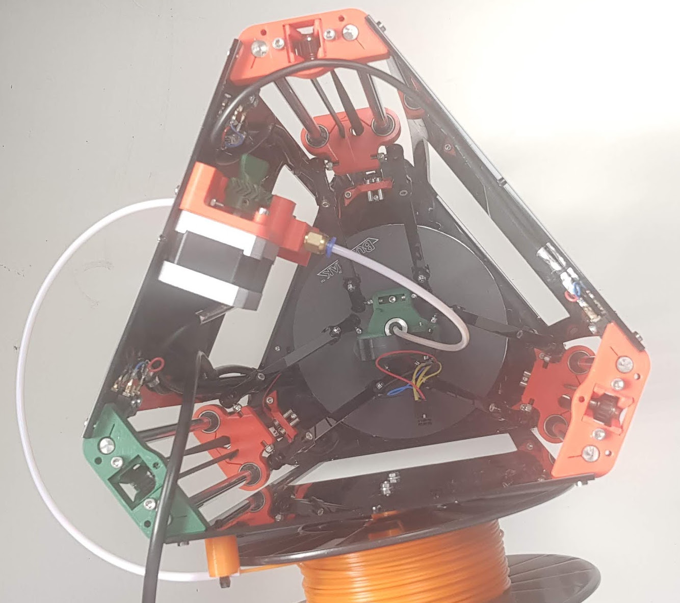
Lead the PTFE filament guide tube from the spacer to which it is attached round to the filament input hole for the extruder drive. It will be too long, so cut it carefully with a sharp blade to a length such that the PTFE loop has no sharp bends, but does not stick out too far. The picture shows the sort of loop round the outside of the corner of the machine that you’re aiming for. |
 |
| NOTE: Whenever you remove the top panel, you should slacken off the belt tension (see next step) first, or there will be a tendency for the idler to be pulled downwards, causing the side panels to bow. |
Drive Pulley and Belts
You will need the following parts:
| # | Component | Qty | Type | |
| 132 | MXL Timing Belt (2.7m) | 1 | Hardware | 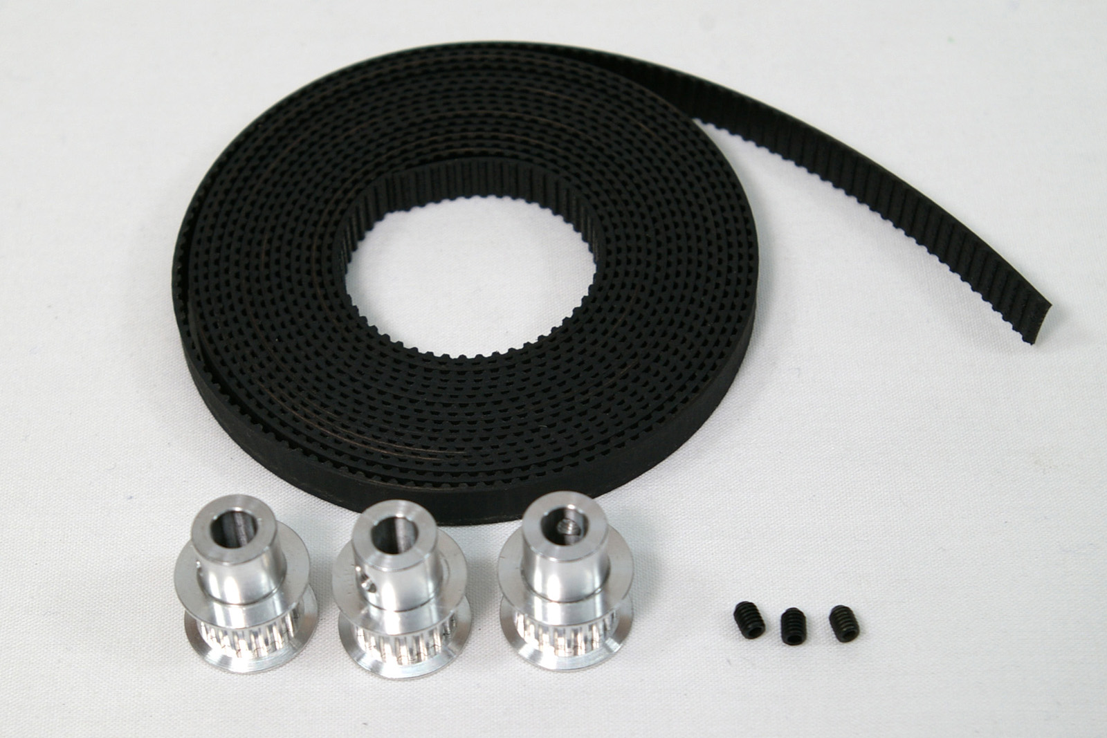 |
| 782 | Aluminium pulley 18 tooth MXL | 3 | Hardware | |
| 782 | M3 grub screw | 3 | Hardware |
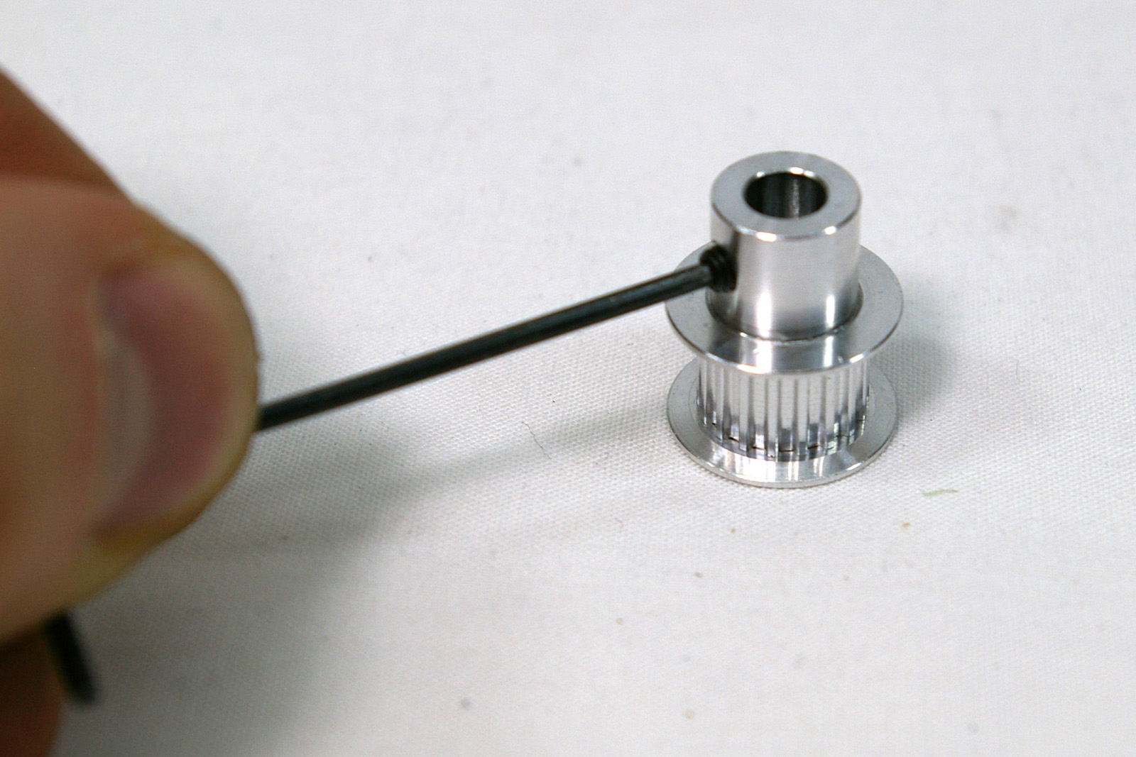
| Fit the grub screw to the pulley.
Some pulleys supplied have two grub screws. When fitting align one with the flat of the motor and remember to tighten them both. |
 |
| The motor shaft has a flat on one side of it. Turn the motor shaft so this points downwards. Slide the pulley onto the motor shaft, shank first. Align the grub screw with the shaft; it tightens onto the flat. Set the pulley so there is approximately 1mm between the face of the motor and the end of the pulley, then tighten the grub screw onto the flat of the motor shaft. You can align the pulley with the slot more accurately later, once the belt is on. | 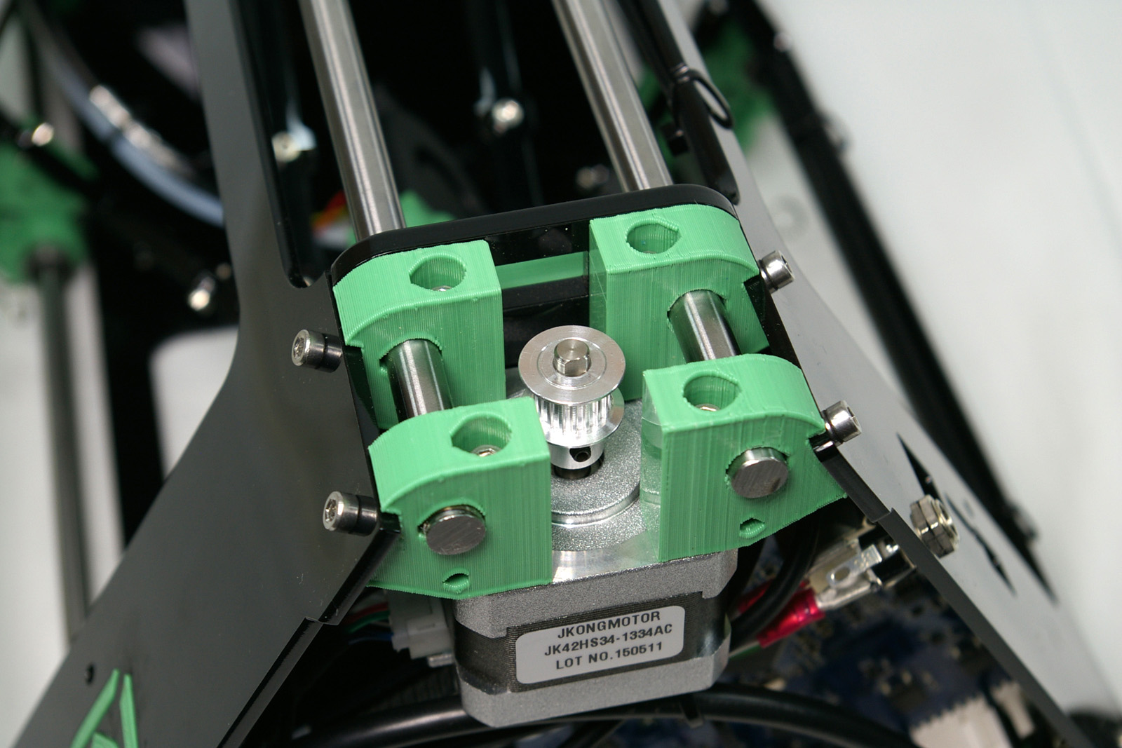 |
| Ensure the idler is at it’s lowest point by unscrewing the cap head screws retaining it from the top. Cut the belt into three equal-length pieces, each of which should be around 900mm long. Run the belt over the idler bearings, toothed side up. | 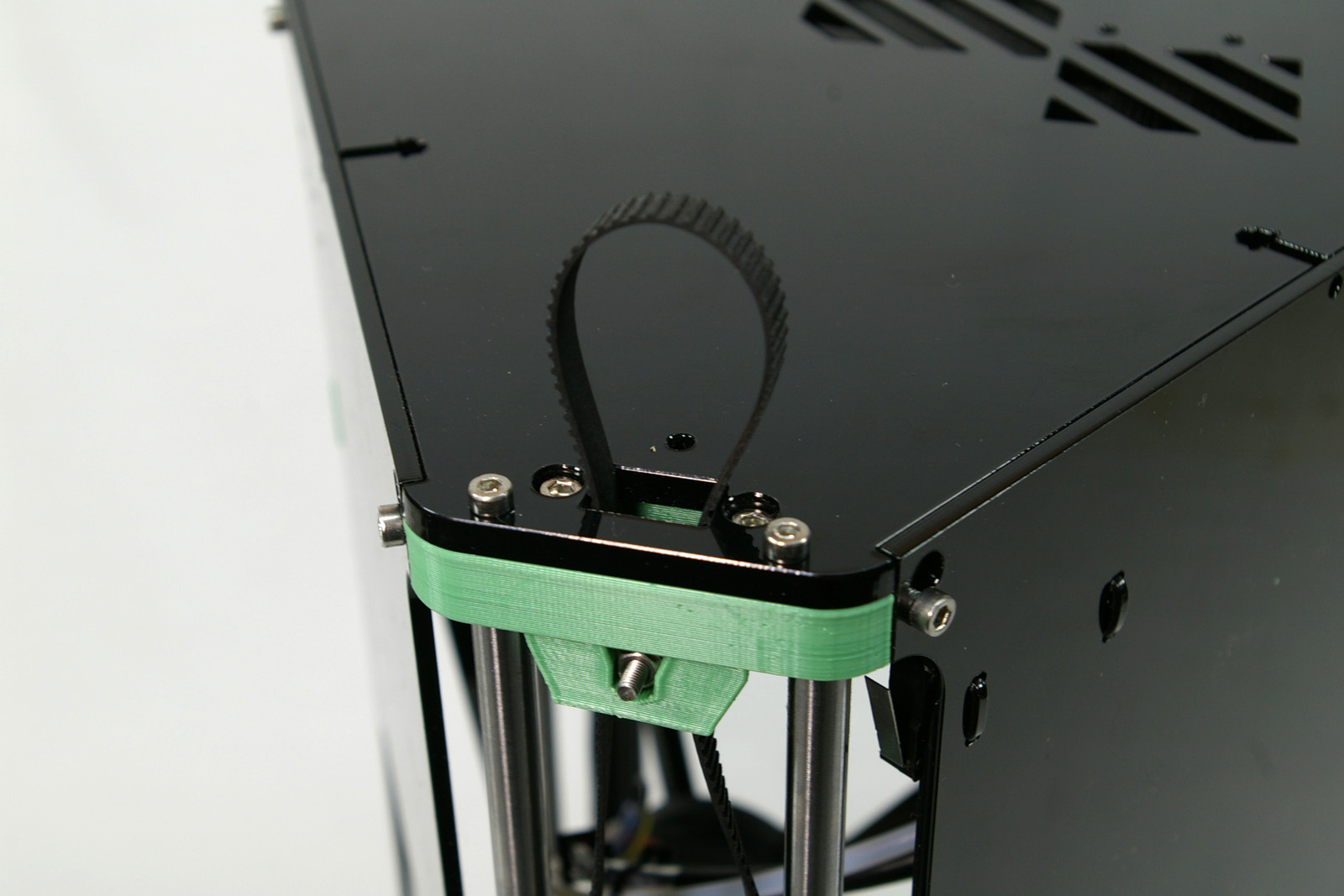 |
| Slip the belt through each slot in the carriage. Add a 180 twist to the belt going through the larger opening in the carriage (on the left side). | 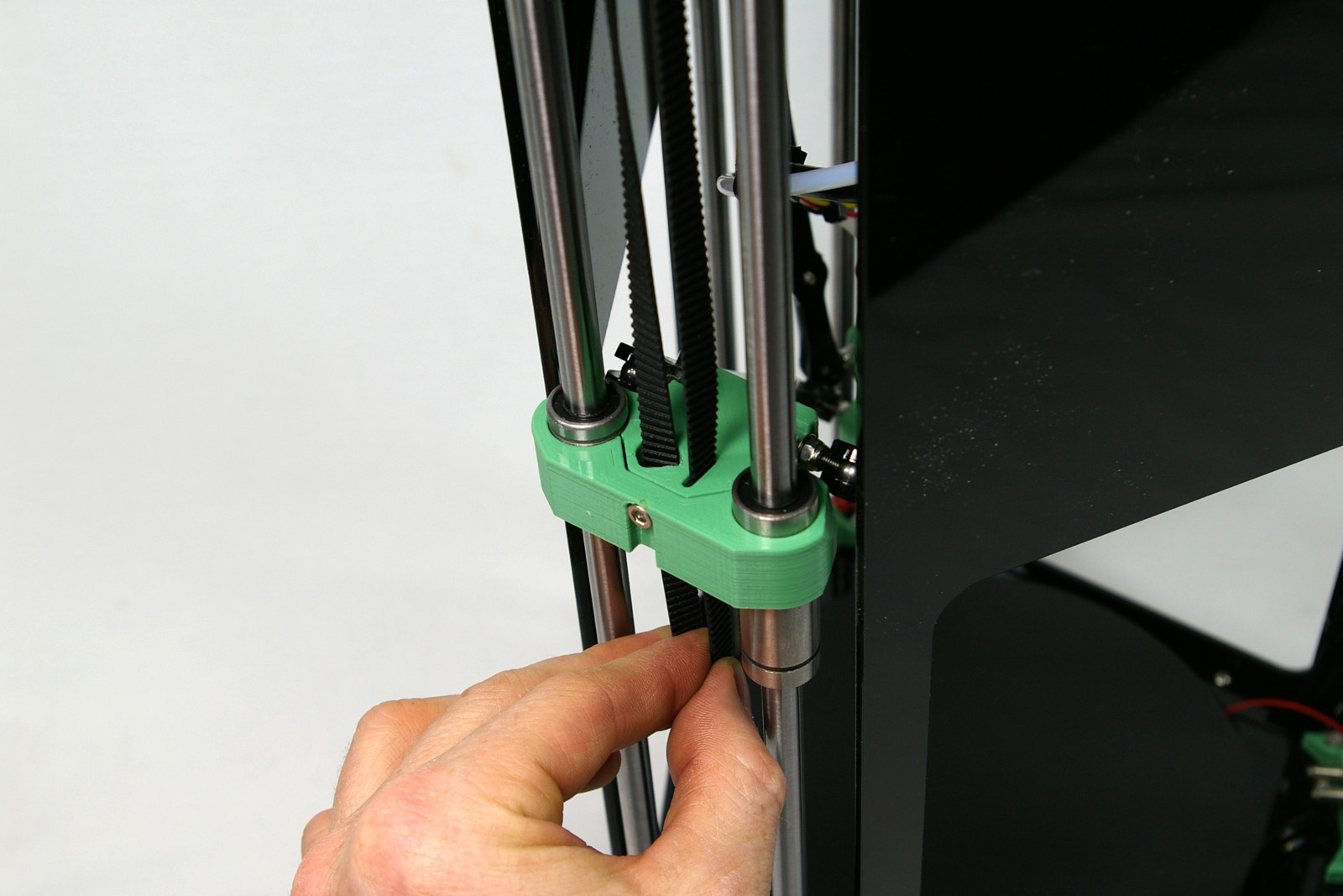 |
| Run the belt down, through the base plate, around the pulley, back up through the base plate, and up towards the carriage. | 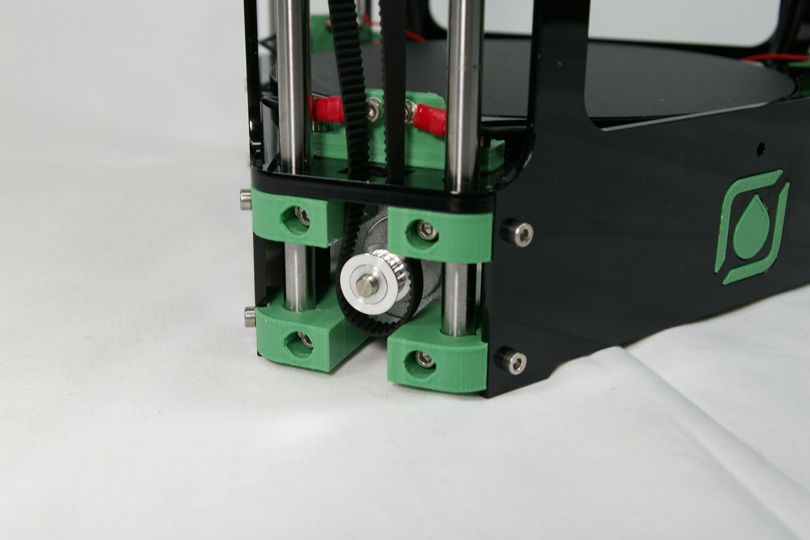 |
| Pull the ends of the belt together, to take the slack out of the belt. Engage the ends of the belt, so the teeth interlock. Push the carriage down while holding the belt stationary, which will force the end of the belt up through the slot in the carriage, locking the belt in the carriage. This may require a reasonable amount of force. | 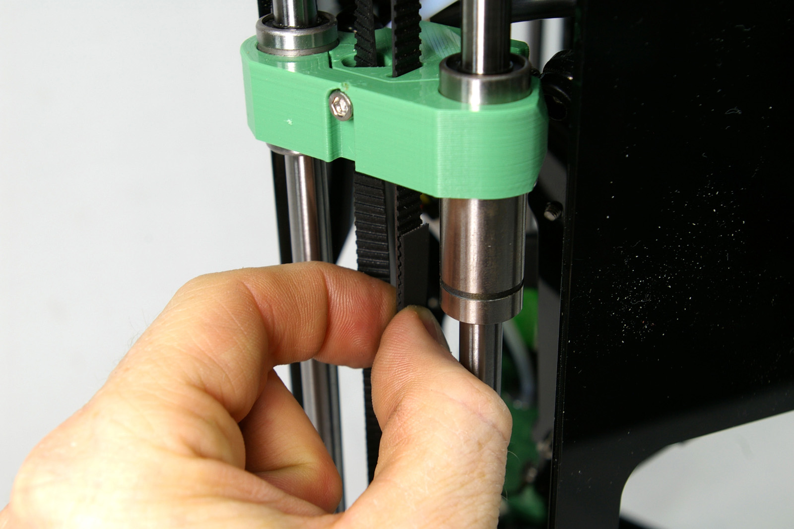
|
| If it’s too tight, you may need to file out the slot a little. If it’s loose in the carriage, use a shim (eg folded paper between the belt and carriage) to make it more positive. It will also get tighter as you tension the belt. | 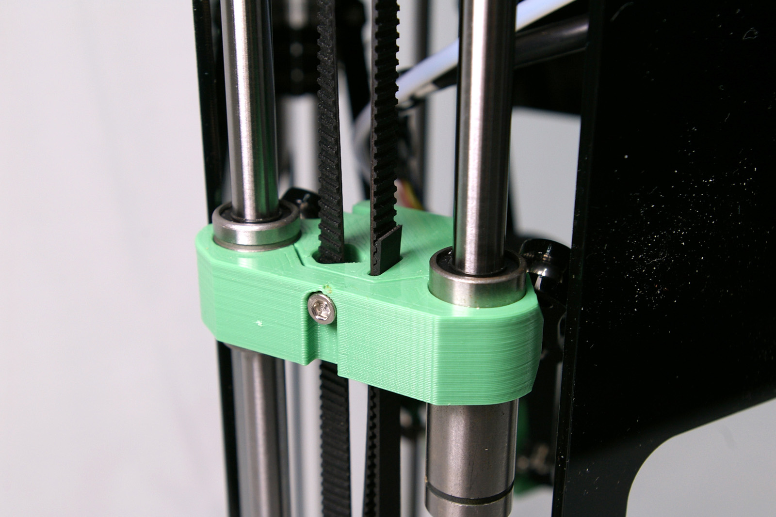 |
| Tension the belt by tightening the two screws holding the idler. To get the tension correct, move carriage to the top, and ‘pluck’ the belt. The tension is about right when you can just hear an audible bass note, similar to a bass guitar. If the belt is too loose, there will be backlash, but if it’s too tight, the motor will struggle.
Check that the motor pulleys are aligned and that the belts are straight. Slacken the pulley grub screws, amke adjustments, and then tighten them again as necessary. |
 |
Repeat the above steps for all three axes.
You have now completed the assembly of your Fisher and you will next move on to commissioning and printing. You will have a few components left over – threaded steel balls, fasteners etc. We have included a few extras as these were parts that went missing easily.
Back – Electronics Next – Commissioning