
Build Instructions – Base Assembly – Tower Assembly – Panels and Rods – Effector Assembly – Extruder Drive
Hot End Assembly – Electronics – Bed, Top Plate and Belts – Commissioning – Printing – Troubleshooting
Goal
By the end of this section, you will have built the effector.
Effector
The effector carries the hot end, and is moved in three dimensions by the movement of the carriages on the towers. You will need the following parts:
| # | Component | Qty | Type | |
| 1301 | Effector | 1 | Printed | 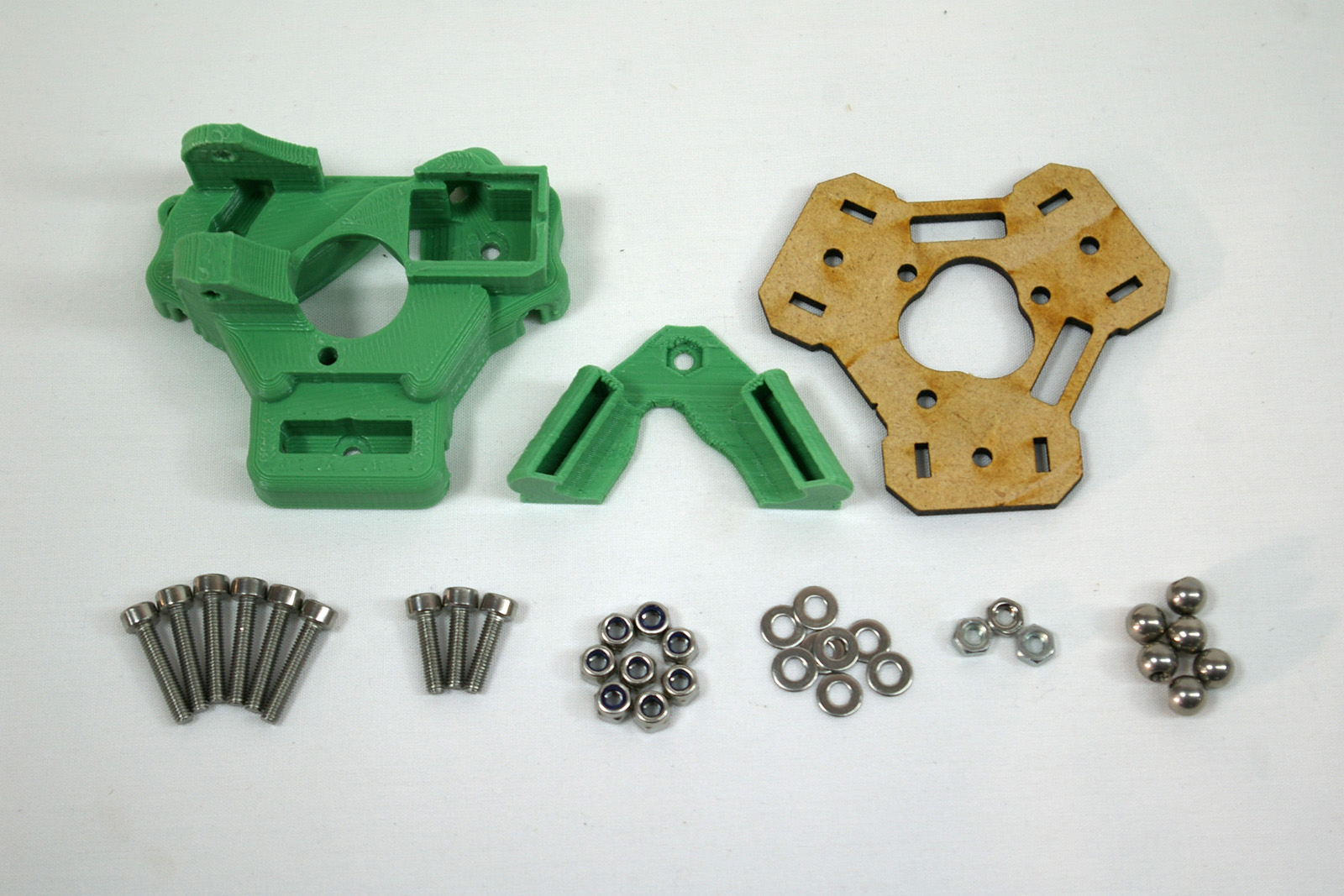 |
| 1247.1 | Nozzle Duct | 1 | Printed | |
| 1223 | Effector Plate (MDF) | 1 | Laser cut bag | |
| 242 | M3x16mm cap head screw | 6 | Fastener | |
| 257 | M3x12mm cap head screw | 3 | Fastener | |
| 204 | M3 Nylock nut | 8 | Fastener | |
| 212 | M3 plain washer | 8 | Fastener | |
| 258 | M3 nut | 3 | Fastener | |
| 1191 | 6mm Threaded steel ball | 6 | Hardware |
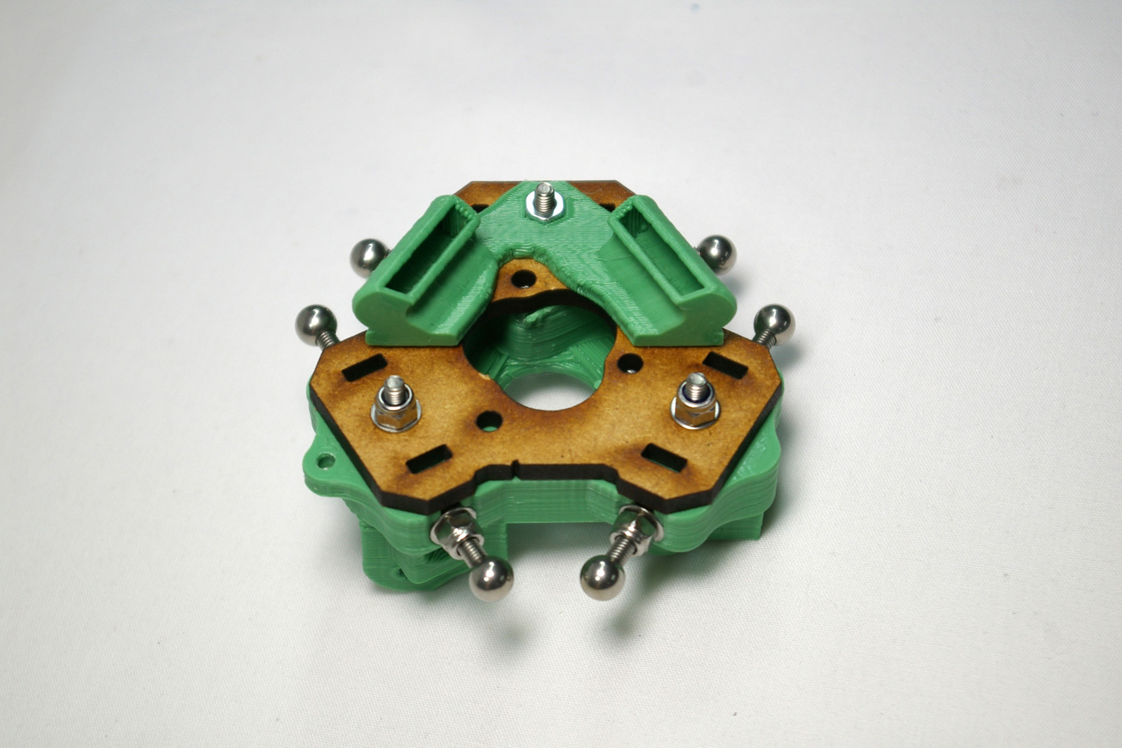
Connecting Rod Joints
| Take the printed effector, and fit six M3x16mm cap head screws, each secured with an M3 washer and M3 Nylock nut, similar to the carriage. | 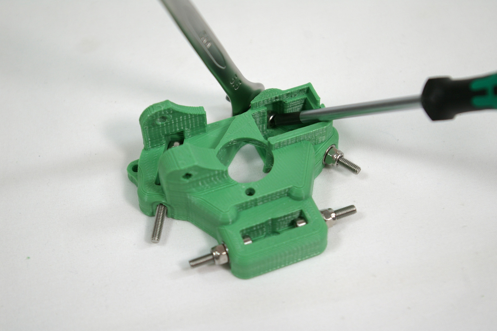 |
| Access to the M3x16mm cap head screws is possibly even more difficult than with the carriages. It really helps having a ball-ended Allen key! Tighten them as with the carriage assembly. | 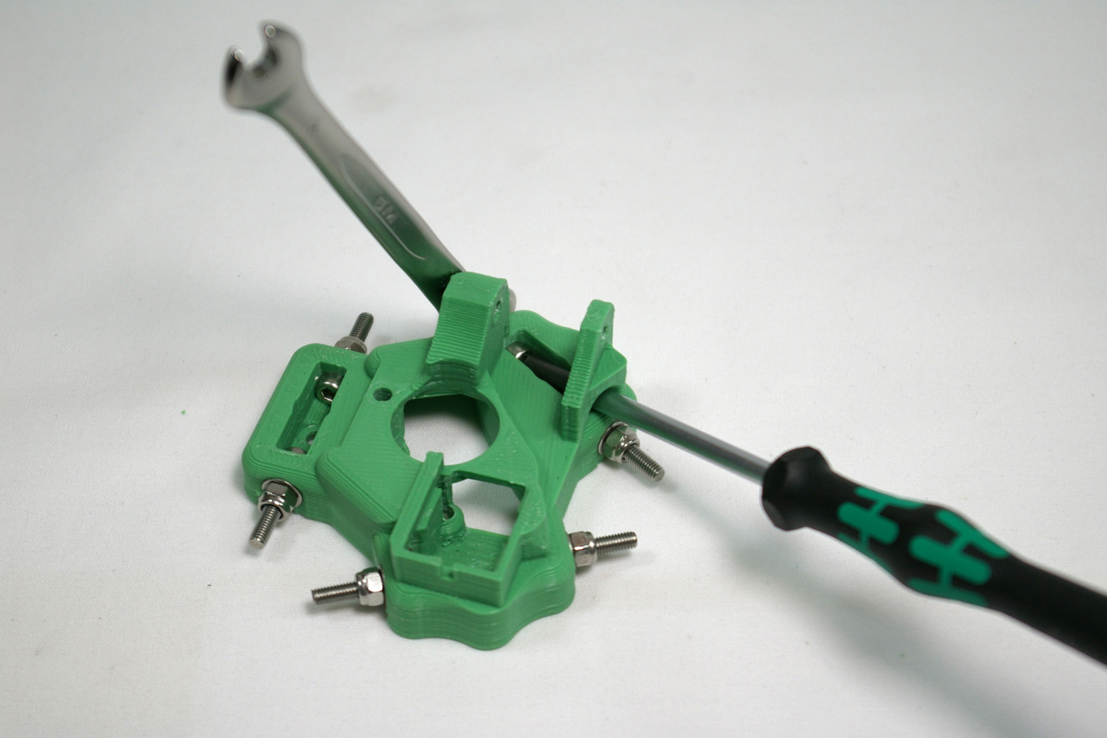 |
| As with the carriages, check that the screws are flat and straight. | 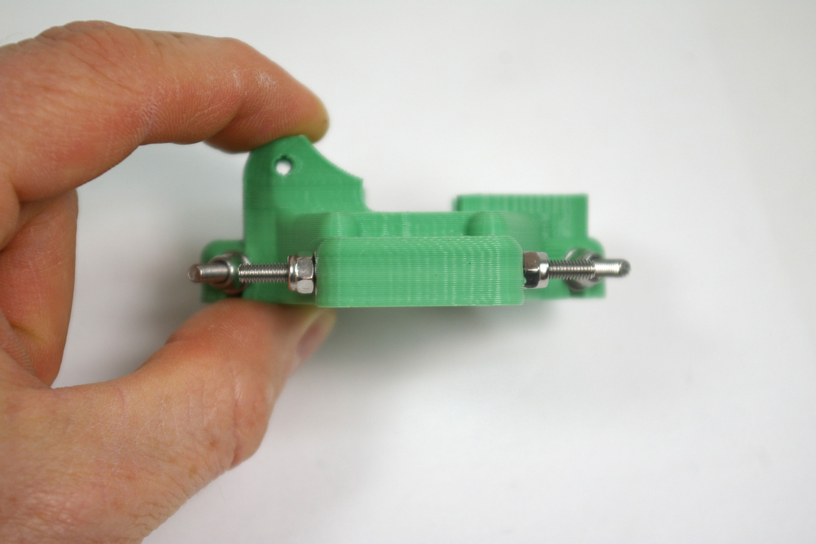 |
| Screw on a 6mm threaded steel ball to each side.
Make sure the balls are free from swarf inside, and that they are threaded. Screw the balls on finger tight, then check that the outside measurement of the balls is close to 57mm. |
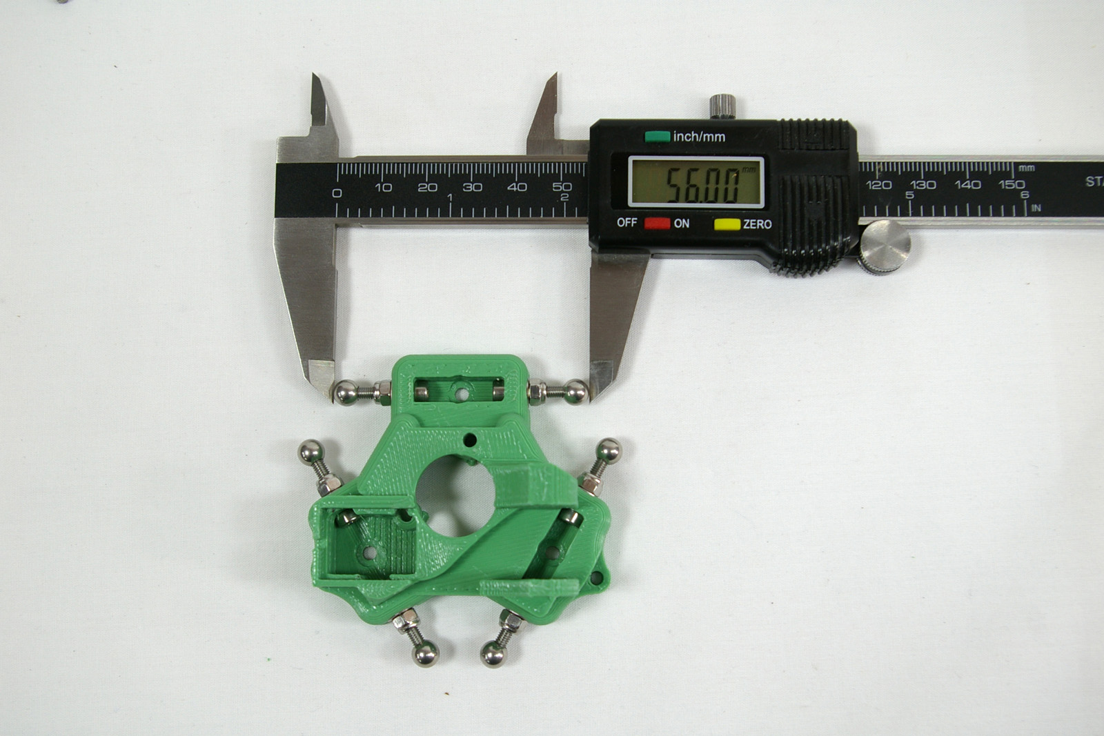 |
| You will now adjust all twelve balls – six on the towers, and six on the effector.
The precise distance between the balls is actually not that important. What is important is that the distance between the balls on the tower carriages (see earlier in the instructions), and those on the effector should all be the same, as close as possible. Get a pencil and paper and carefully measure and note down all six distances between the outside of all the balls. You are going to make them all the same distance apart as the biggest distance in your list. Rubber or surgical gloves are useful to avoid getting superglue on your fingers. Remove the balls in pairs, put a very small dab of superglue on the ends of the threads, and screw the balls back on. Adjust them before the glue sets to have the same gap as the biggest distance on your list. It may help to practice this a few times without the glue before doing it for real. Do not get glue on the surface of the balls. Leave them to set. |
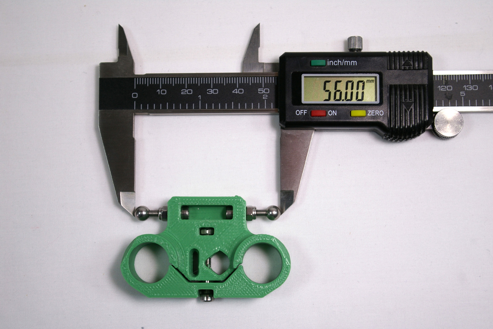 |
| NOTE: The rods that connect the carriage and effector must be parallel, so that the movement of the effector is always square to the carriage. If the distance between the balls is not the same, the rods will not be parallel, and the movement of the effector and hot end will not be consistent, and you may end up printing parts that are not dimensionally accurate. |
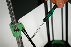
| When the glue has set, take the six rods that you set asside and attach them to the carriages.
If you wish you may put a little silicone grease on the six carriage balls to lubricate them and the rods. But don’t use mineral-oil based grease as this may damage the rods. And don’t lubricate the balls on the effector – that will be done later. Gently spread each rod, and slip it over the ball, so the hole in the rod locates around the ball. Fit it with the top screw head facing towards the centre of the machine; this is the easier way around for accessing the screws at the top and bottom. Tighten the screw until the rod holds the ball. If you wiggle the rod, there should be no play in the joint. |
 |
Effector Plate
| Turn the effector over, and fit two M3 nuts in the captive holes underneath. | 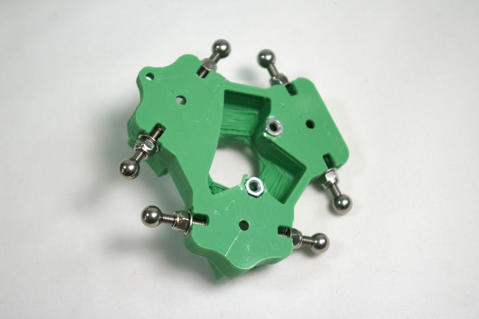 |
| Take the MDF effector plate, and orientate it so that the holes line up with M3 nuts, and duct holes match the effector. It only fits correctly one way! | 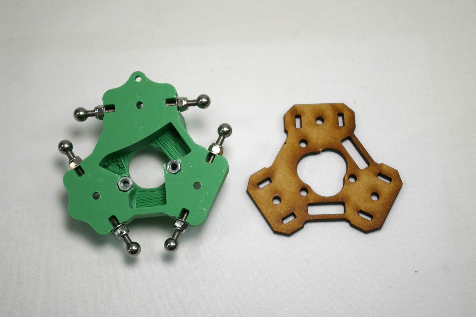 |
| From the top of the effector, put three M3x12mm cap head screws through the central holes, between the connecting rod joint screws. | 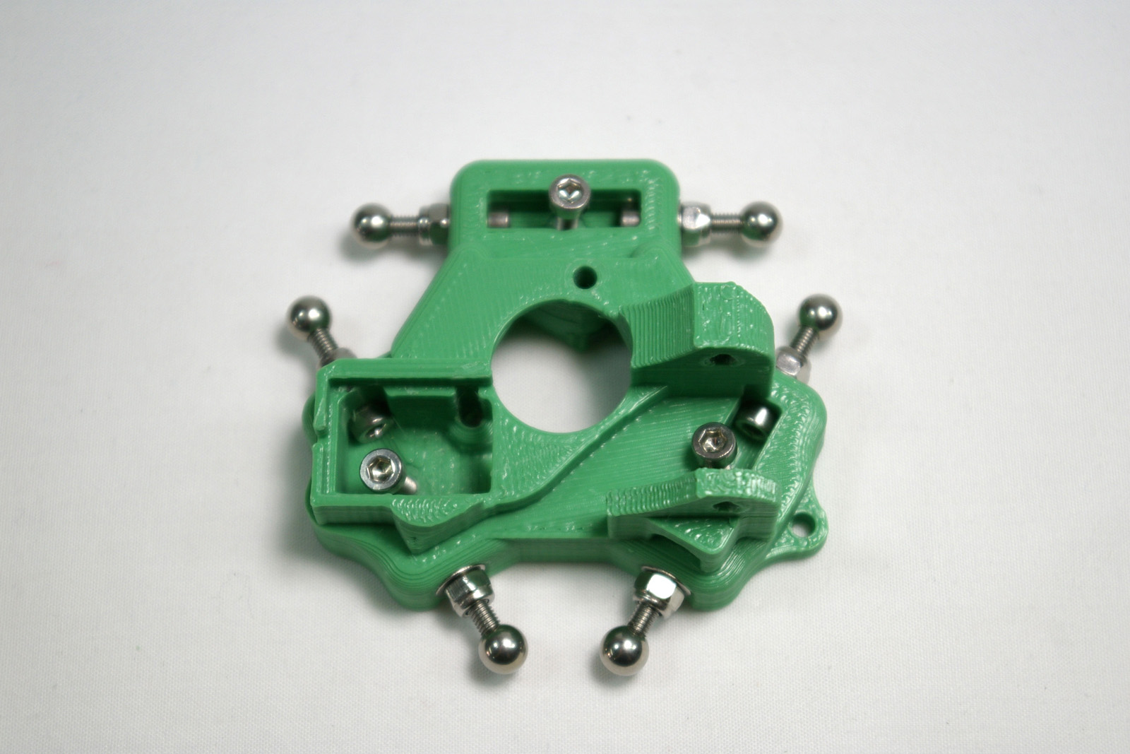 |
| Turn the effector back over, and fit the MDF effector plate, again making sure of the alignment. Use an M3 washer with M3 nylock nut on two of the screws, as shown. | 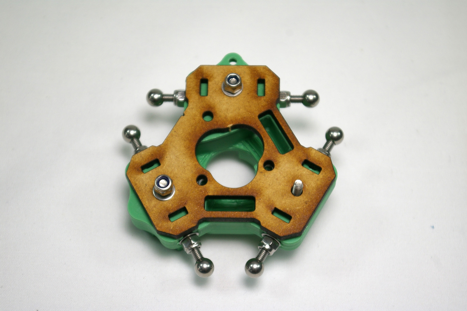 |
| Fit the fan duct on the final screw, with an M3 nut. Tighten all three screws to pull the effector together. | 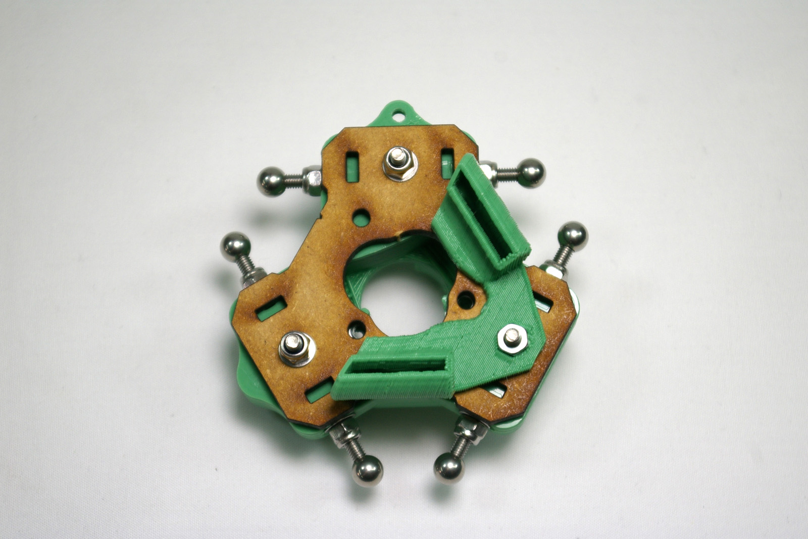 |
Back – Panels and Rods Next – Extruder Drive