
Build Instructions – Base Assembly – Tower Assembly – Panels and Rods – Effector Assembly – Extruder Drive
Hot End Assembly – Electronics – Bed, Top Plate and Belts – Commissioning – Printing – Troubleshooting
Goal
 By the end of this section, you will have completed the motor towers.
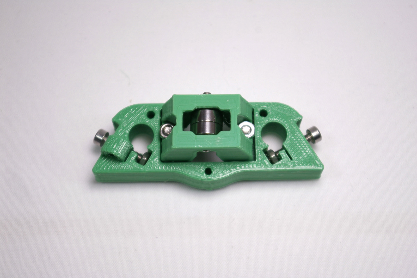
Carriage
The carriage runs on the towers, and three of them combine to move the effector, which carries the hot end, that prints parts. You will need the following parts:
| # | Component | Qty | Type | |
| 1304 | Carriage | 1 | Printed Part | 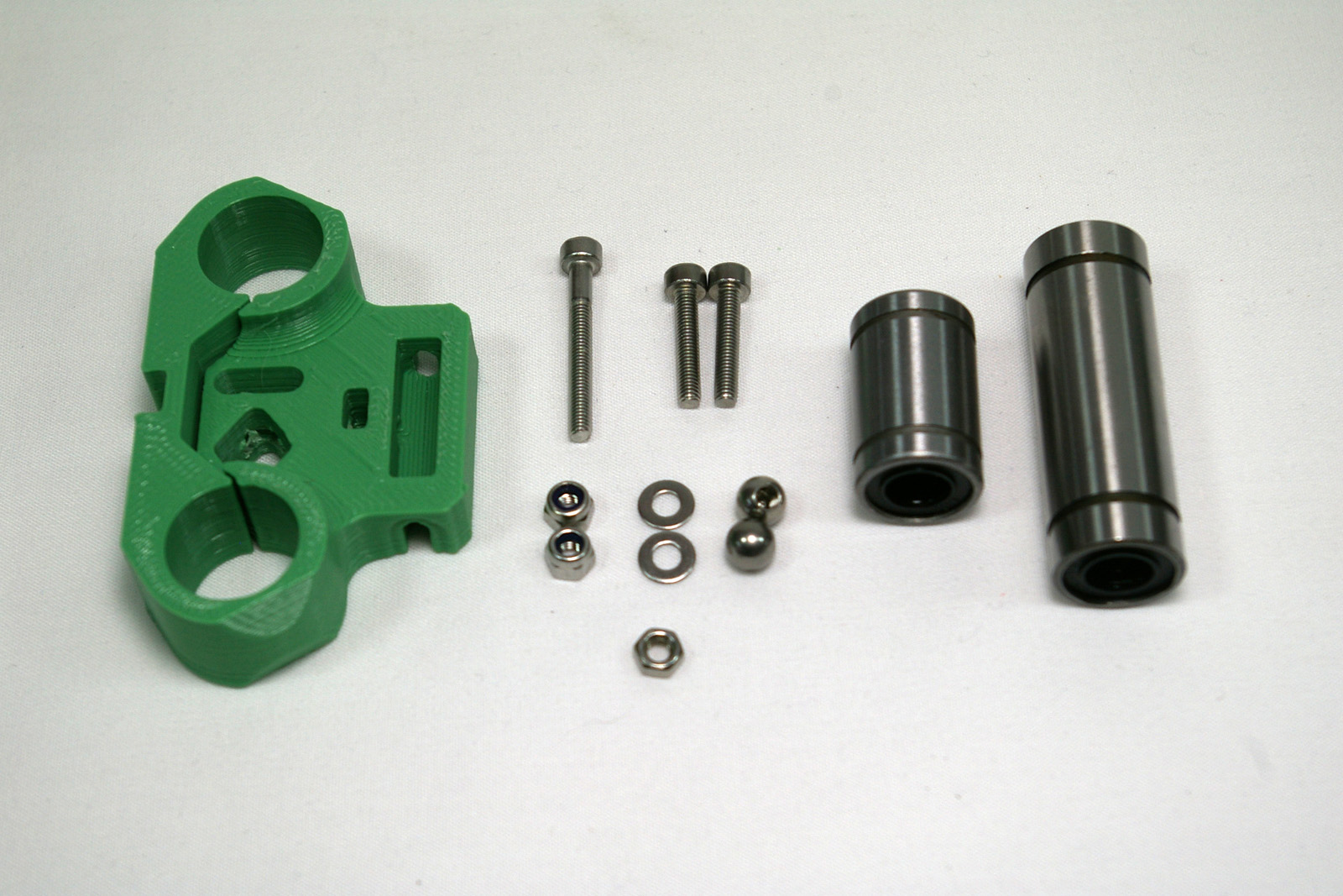 |
| 112 | M3x25mm cap head screw | 1 | Fasteners | |
| 242 | M3x16mm cap head screw | 2 | Fasteners | |
| 204 | M3 Nylock nut | 2 | Fasteners | |
| 212 | M3 plain washer | 2 | Fasteners | |
| 258 | M3 nut | 1 | Fasteners | |
| 1191 | 6mm threaded steel ball | 2 | Fasteners | |
| 287 | LM8UU linear bearing | 1 | Hardware | |
| 1182 | LM8LUU linear bearing | 1 | Hardware |
Connecting Rod Joints
| Using an M3x16mm cap head screw, fit this into the carriage as shown. Put an M3 plain washer, then an M3 Nylock nut, to hold it in place. | 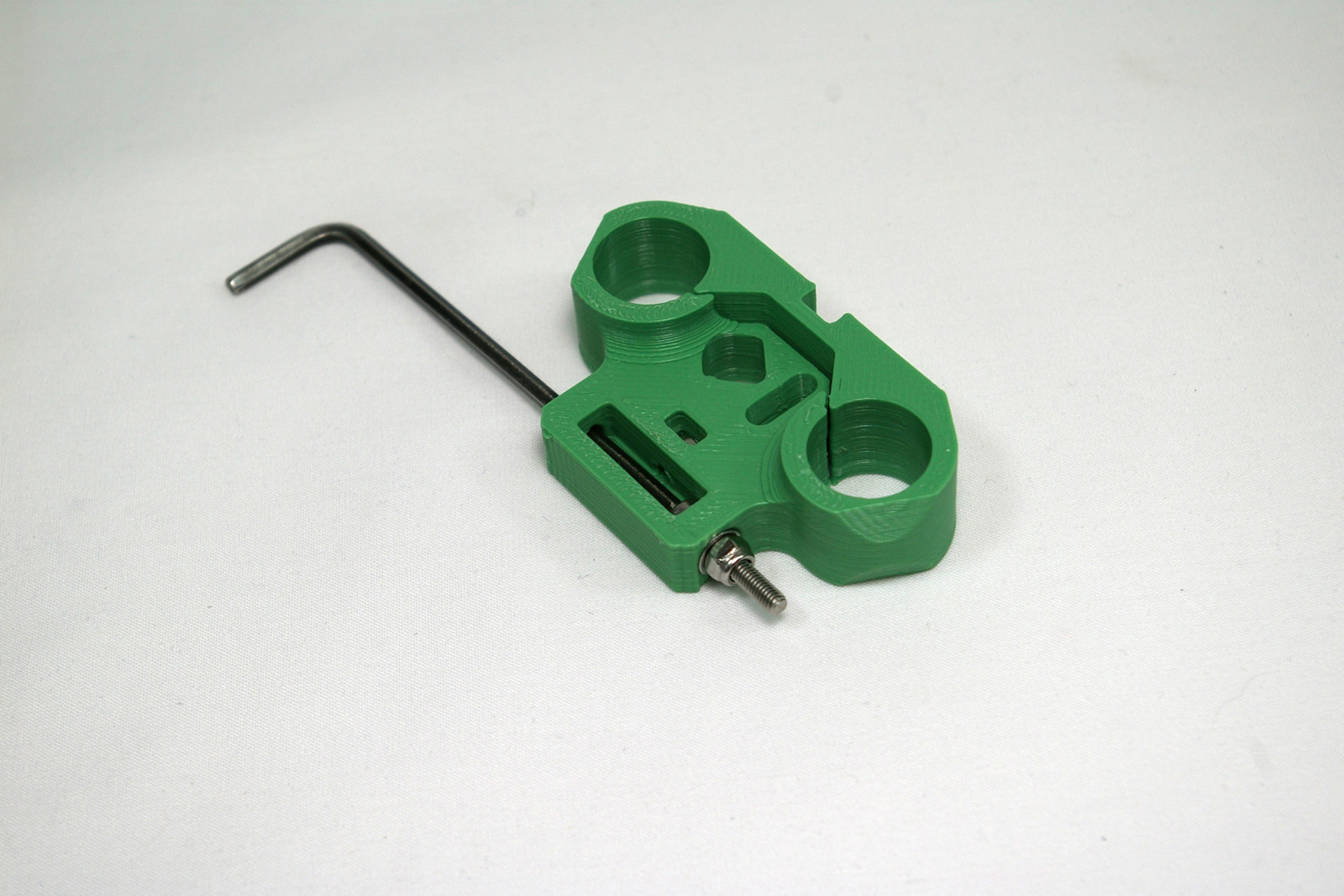 |
| Place the second M3x16mm cap head screw in the other side, secured with an M3 plain washer and M3 Nylock nut. This screw can be hard to access. It’s very handy to have a ball-ended Allen key, as this can hold the screw at an angle. | 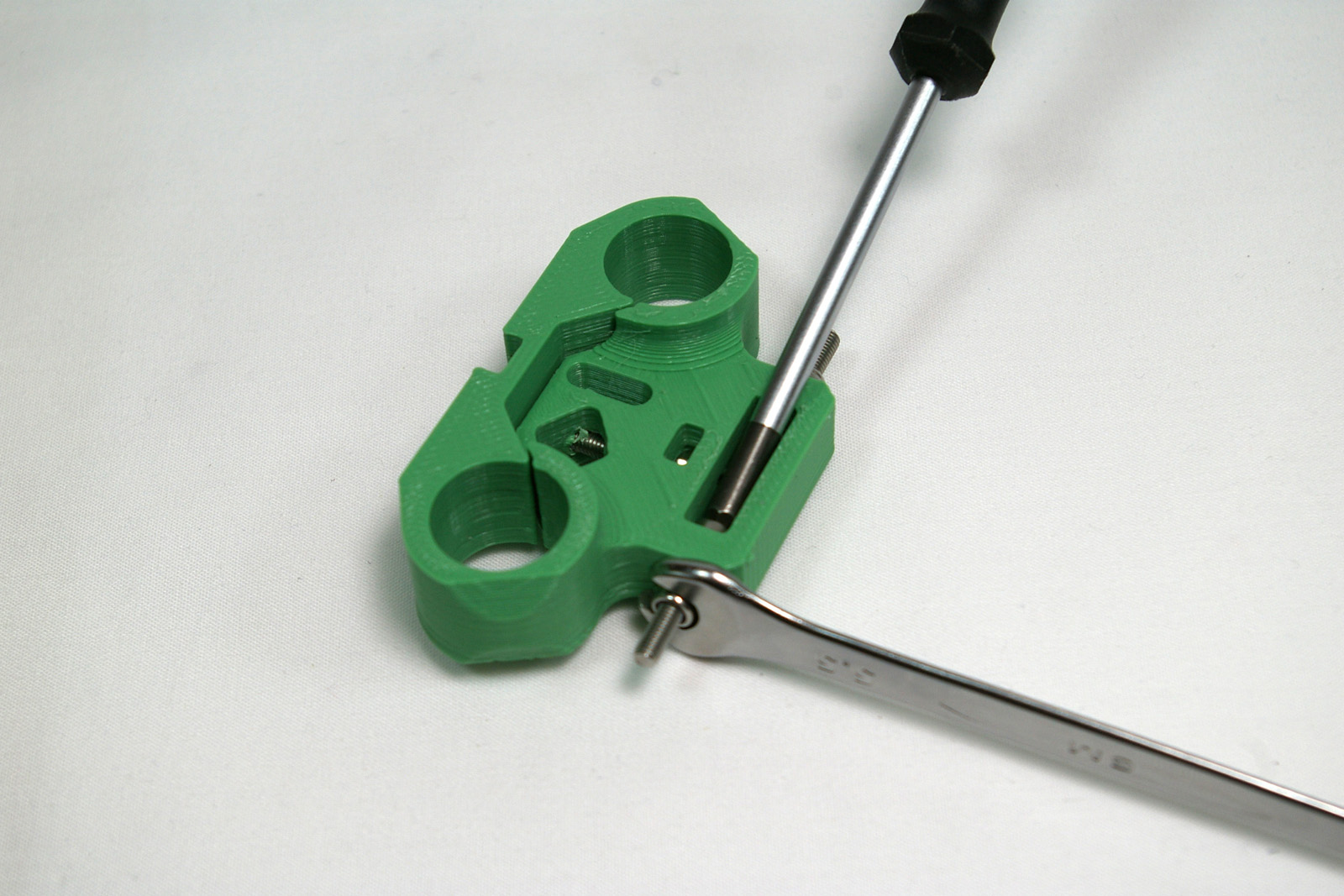 |
| But you can do the same thing with a normal Allen key, using the short side. Alternatively, cut down the Allen key, to make it easier to access the cap head screw. | 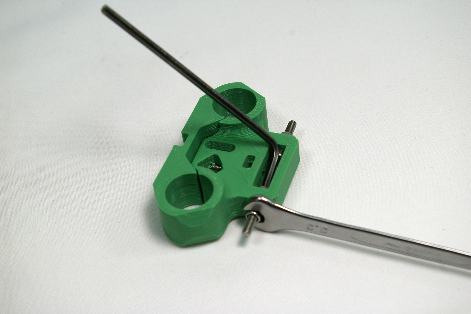 |
| Make sure the screws are straight and level. If they are not, this may distort the print. The nyloc nut and washer should force the screw straight. Tighten them so there is no movement in the screw. This shouldn’t need to be really tight, just pinched up. | 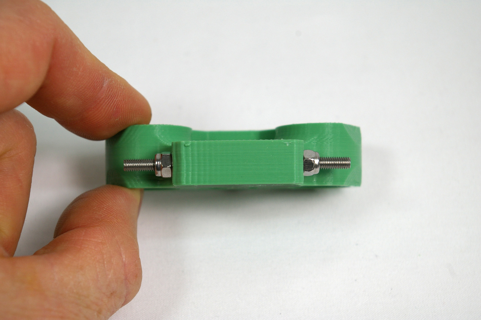 |
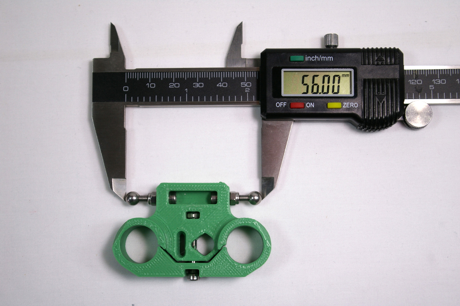
| Screw on a 6mm threaded steel ball to each side. Before fitting, make sure the balls are free from swarf inside, and that they are threaded. Screw the balls on hand tight, then check that the outside measurement of the balls is close to 57mm.
The final adjustment to the balls will be made later.
|
 |
Linear Bearings
| Drop the M3 plain nut into the nut trap in the centre of the carriage. | 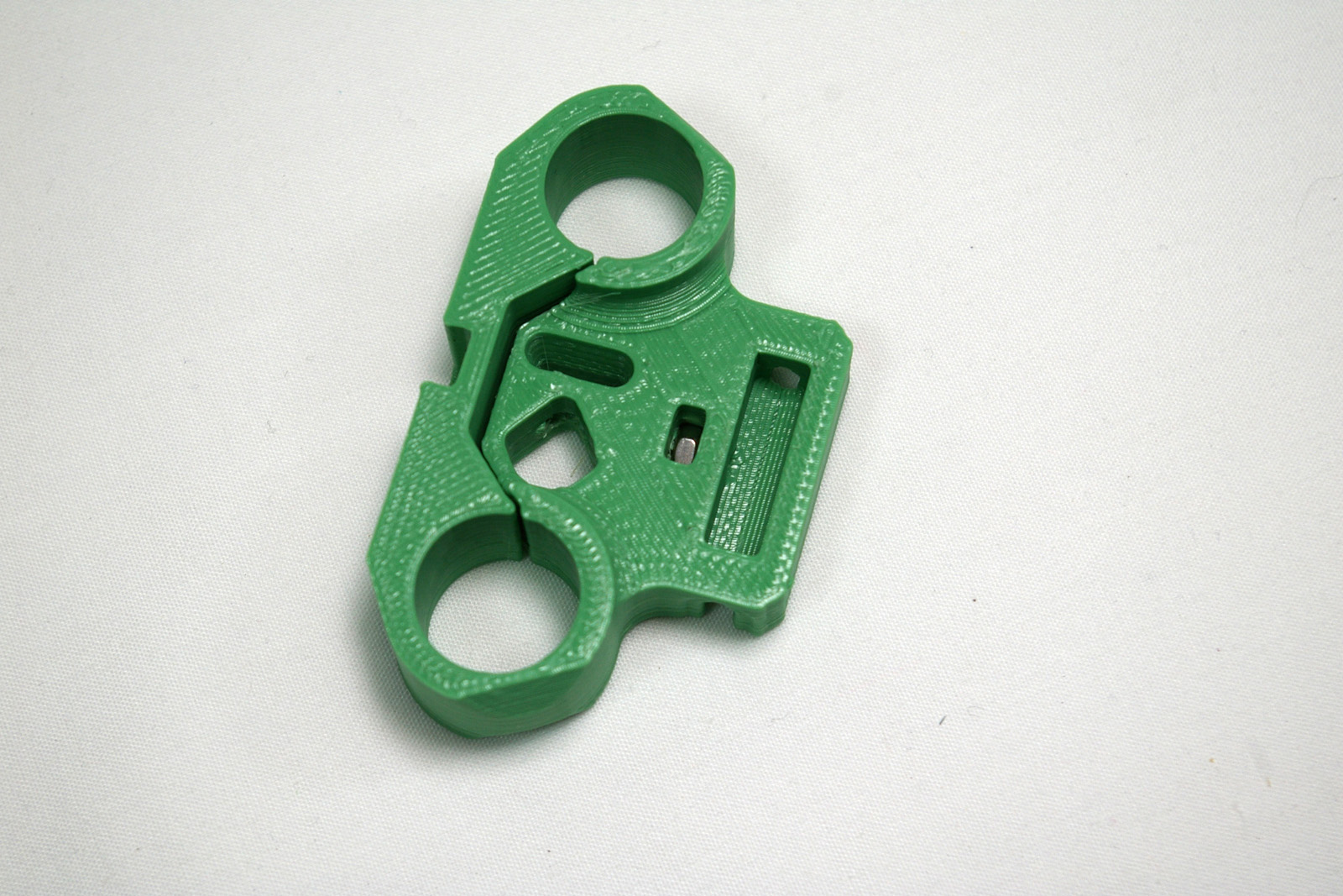 |
| Screw in the M3x25mm cap head screw from the front of the part. Don’t tighten it yet. | 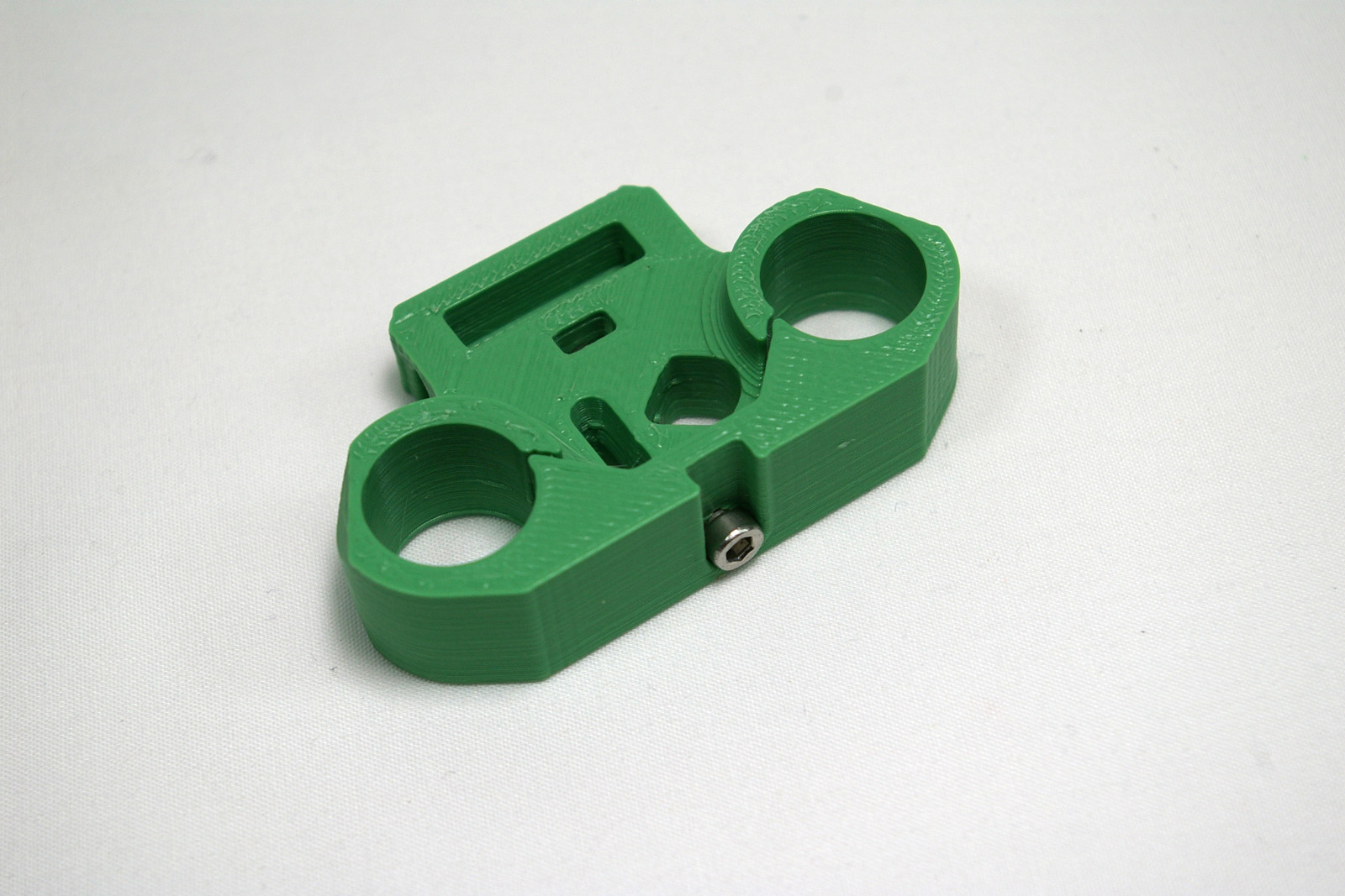 |
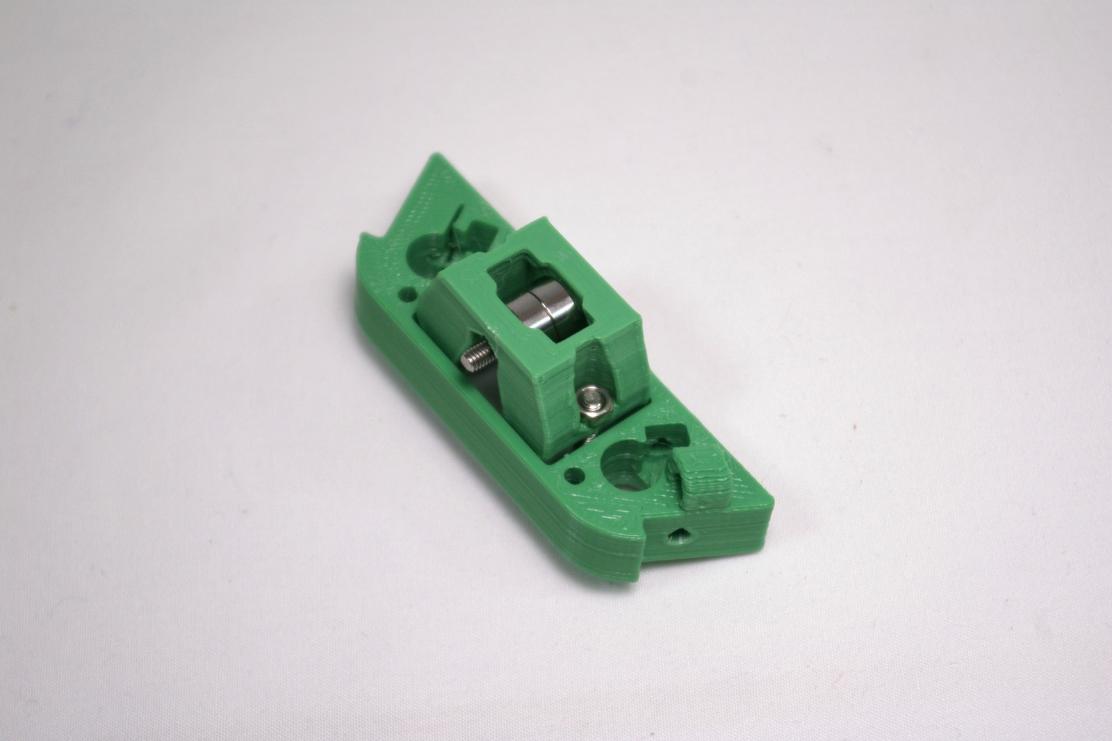
| Slide in the two 8mm linear bearings as shown. Note the orientation. | 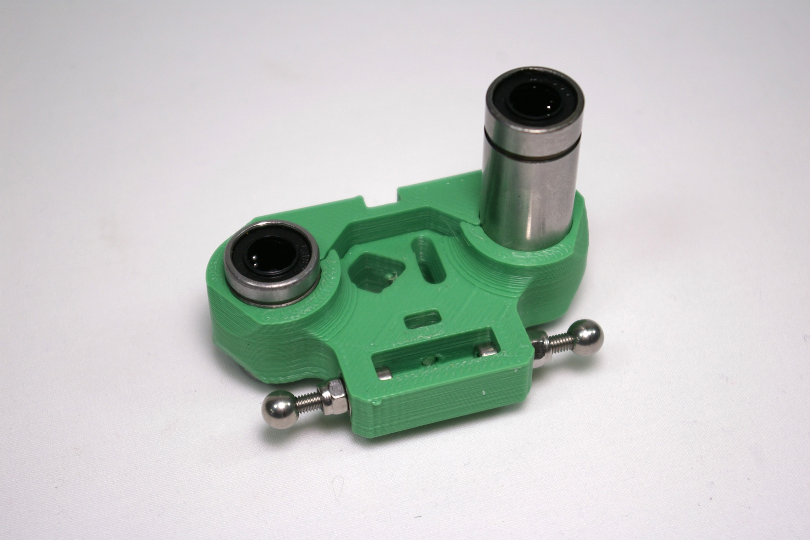 |
| The short bearing should have equal amounts of it showing above and below the carriage. The long bearing should be set at roughly the same height as the short bearing, on the top. Tighten the M3x25mm cap head screw to hold them in place. | 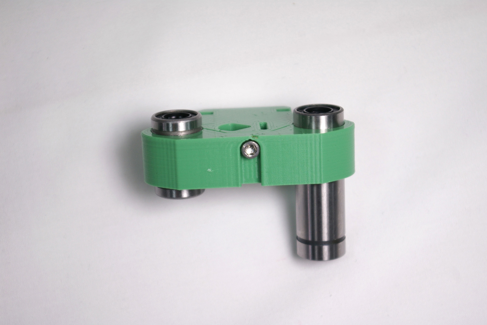 |
Repeat, Then Fit
| Build two more exactly the same.
|
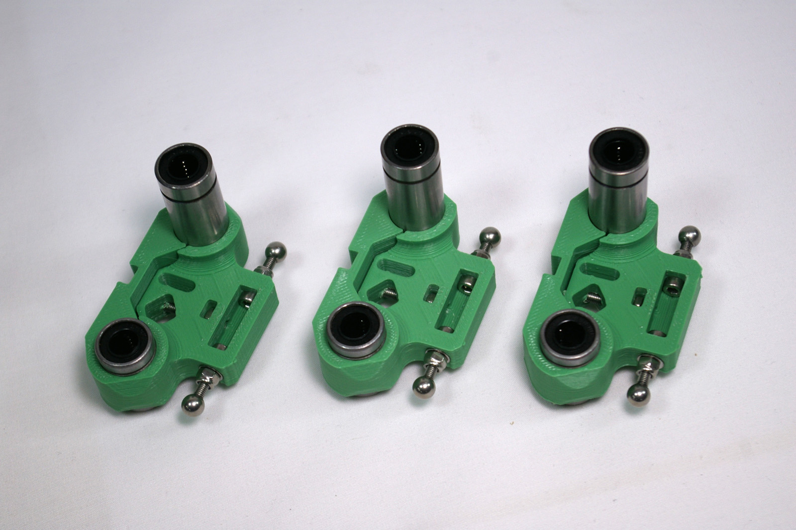 |
| Slide each carriage onto a tower, with the balls inwards, and the longest bearing on the right, downwards, as shown. | 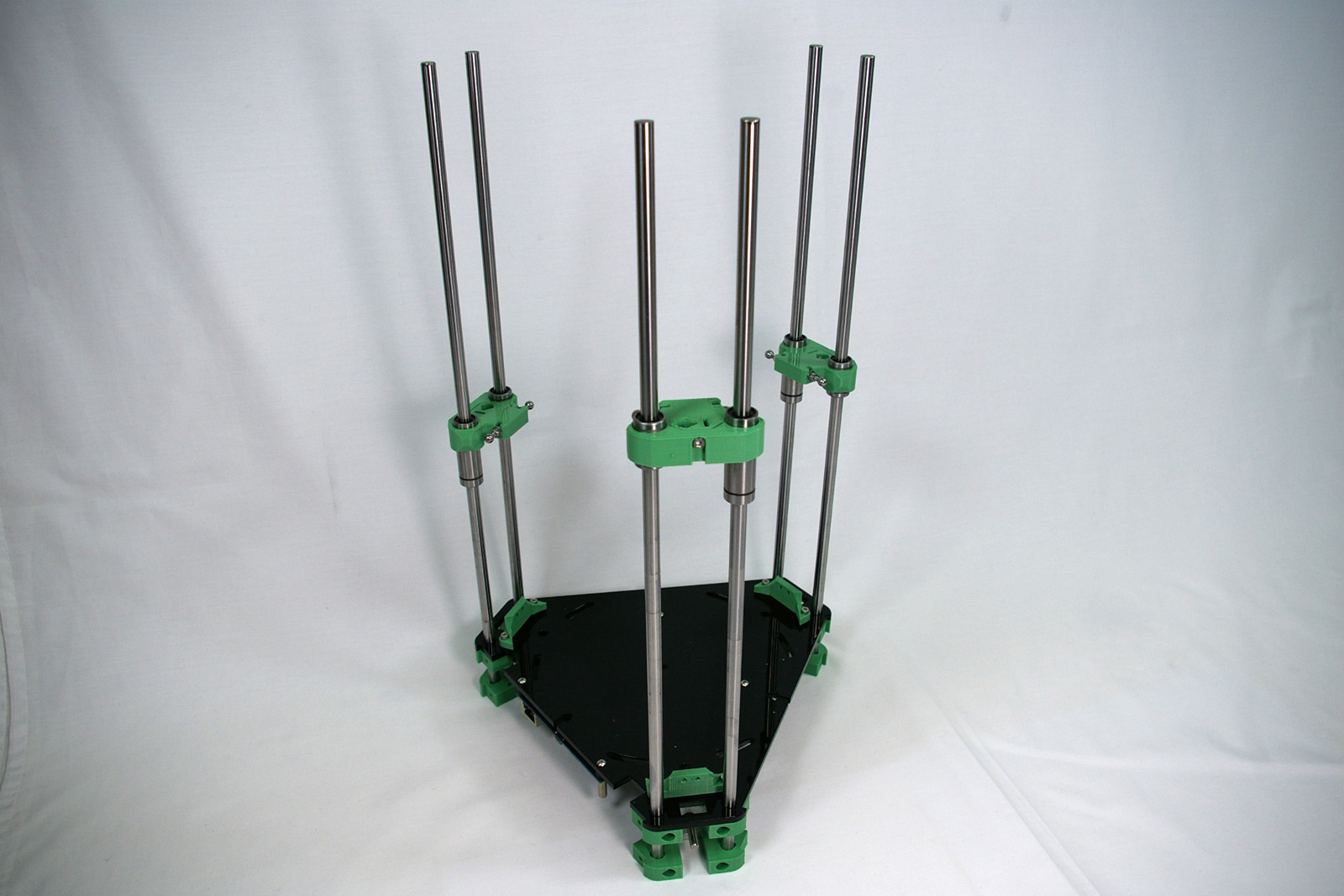 |
| NOTE: Take special care when sliding the bearings over the ends of the rods to ensure the axes of the rods and the bearings are aligned. It is possible to cause irreparable damage to the bearings by sliding them over the rod ends whilst misaligned, causing some of the balls to fall out. |
Idler Bracket Assembly
The idler bracket is at the top of the tower, and provide the bearing around which the belt will go, which drives the carriage. You will need the following parts:
| # | Component | Qty | Type | |
| 1285 | Idler bracket | 1 | Printed | 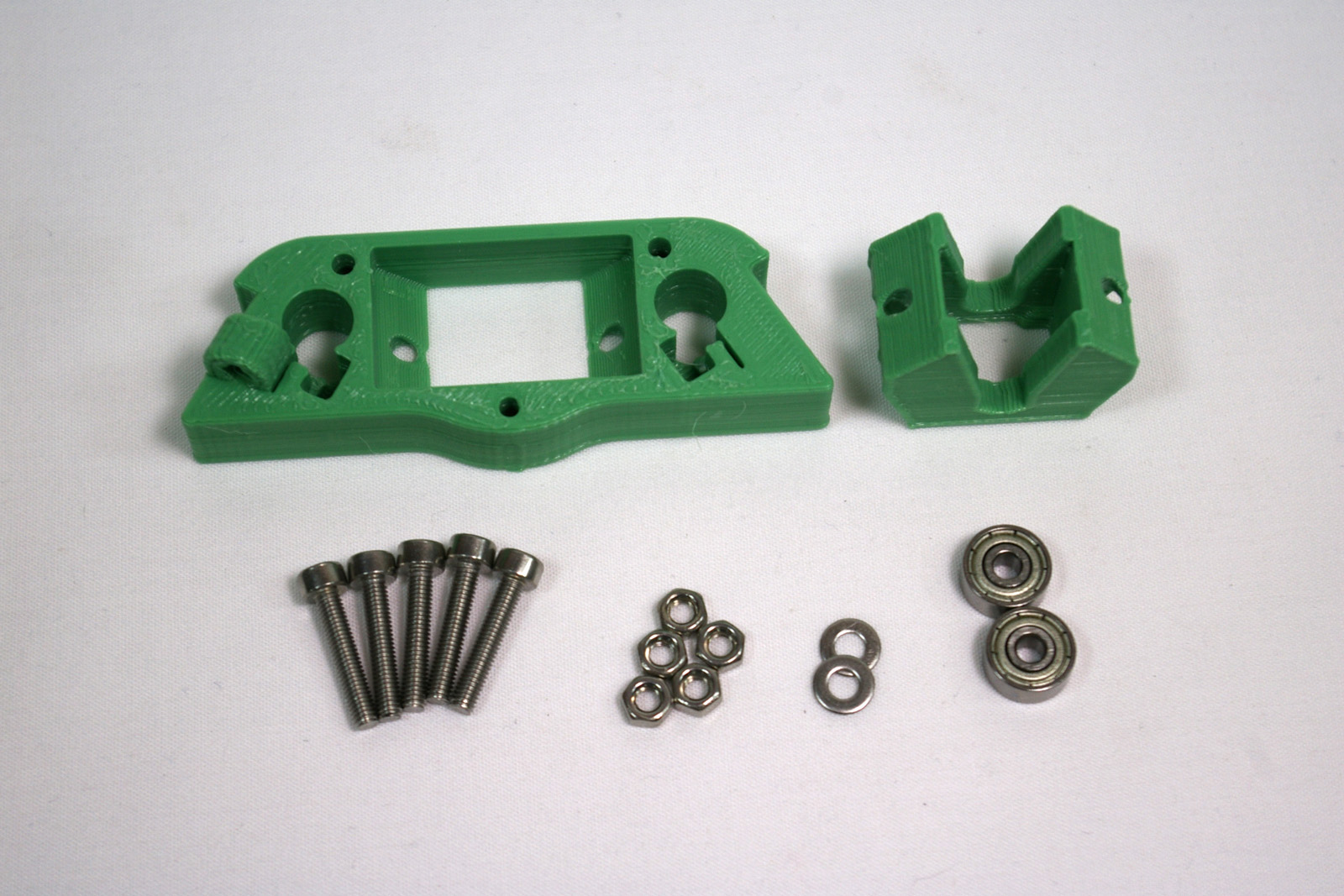 |
| 1243.1 | Idler | 1 | Printed | |
| 242 | M3x16mm cap head screw | 5 | Fastener | |
| 258 | M3 nut | 5 | Fastener | |
| 212 | M3 plain washer | 2 | Fastener | |
| 279 | 623 bearing | 2 | Hardware |
Idler
| Assemble the idler bearing in this order: M3x16mm cap head screw, M3 plain washer, 2 x 623 bearing, M3 plain washer, M3 nut. | 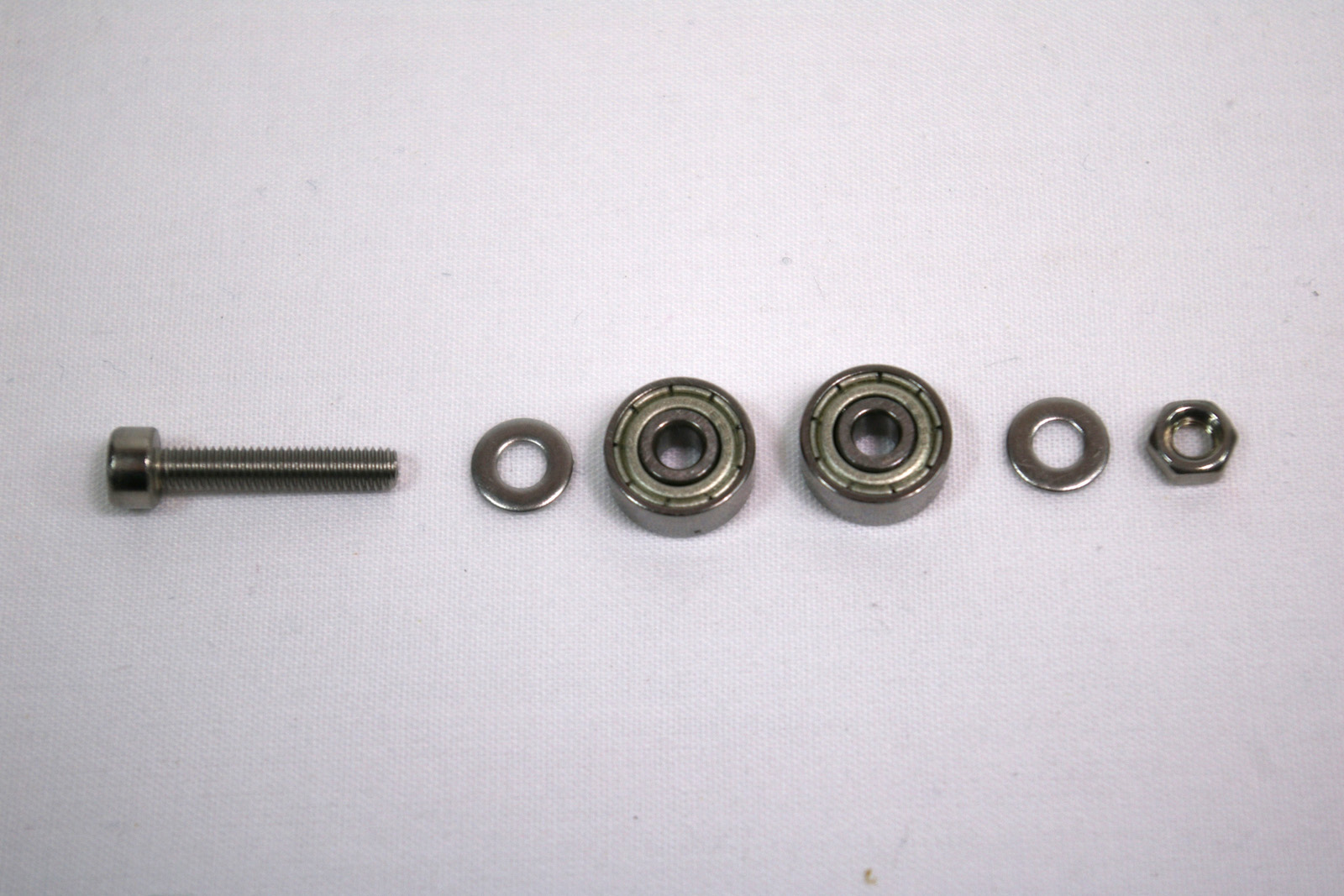 |
| Tighten this up, but check that the 623 bearings can rotate freely. If they stick, try turning the washer around. These tend to have a rounded side and a more flat side; put the rounded side towards the bearing. | 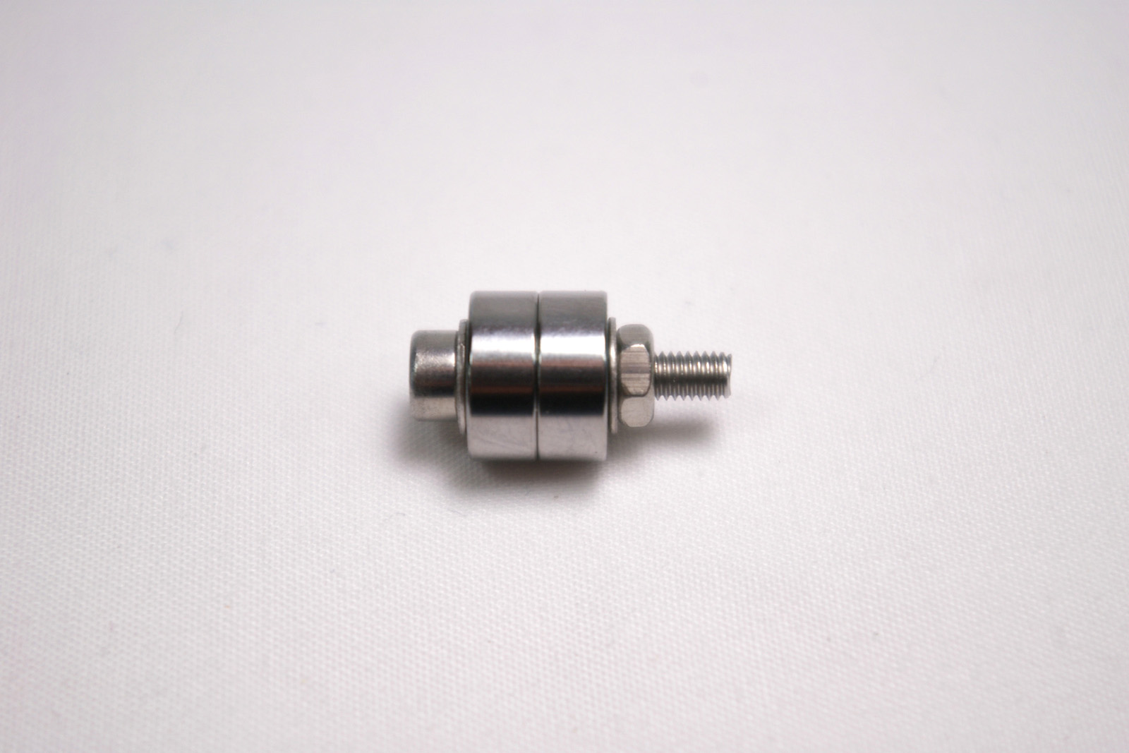 |
| Push the idler bearing assembly into the printed idler part. The two side are different, with a seat for the M3 nut on one side, and for the screw head on the other. | 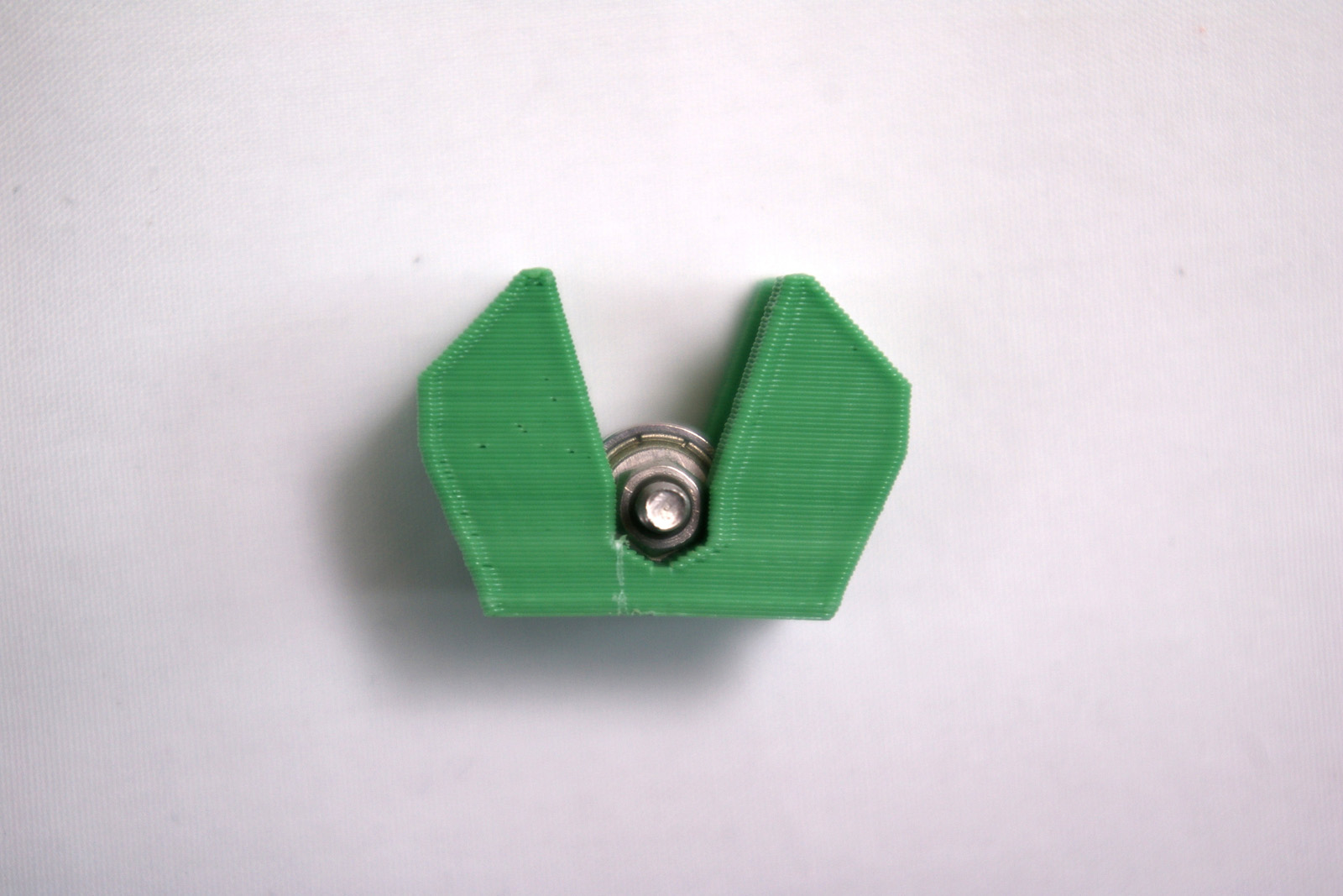 |
| Make sure the idler bearing assembly is seated fully in, and the bearings are level with the idler printed part. | 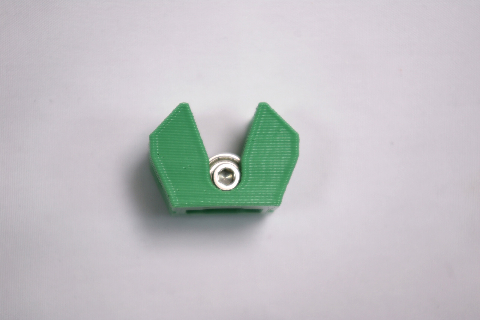 |
Idler Bracket
| Push two M3x16mm cap head screws through the idler bracket, as shown. | 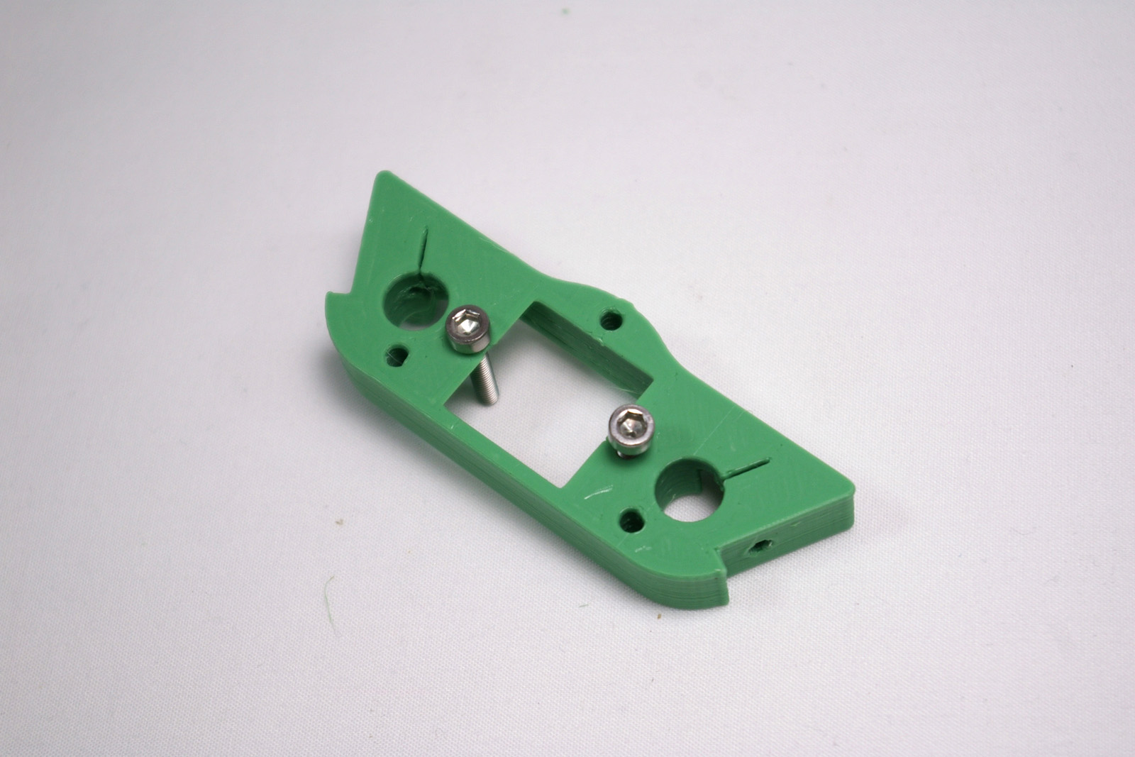 |
| Push an M3 nut into each recess in the idler printed part. Screw the idler up into the recess in the idler bracket. This will later be used to tension the drive belts, so may be left loose at this stage. |
 |
| Drop an M3 nut into the nut trap recess, and screw in the last two M3x16mm cap head screws as shown. These will hold the top of the side panels, so again, leave these loose at this stage.Take the idler bearing assembly out of its bracket and put it to one side. It will be re-inserted later. |
 |
Repeat, then fit, again
| Build two more idler brackets, exactly like the first. | 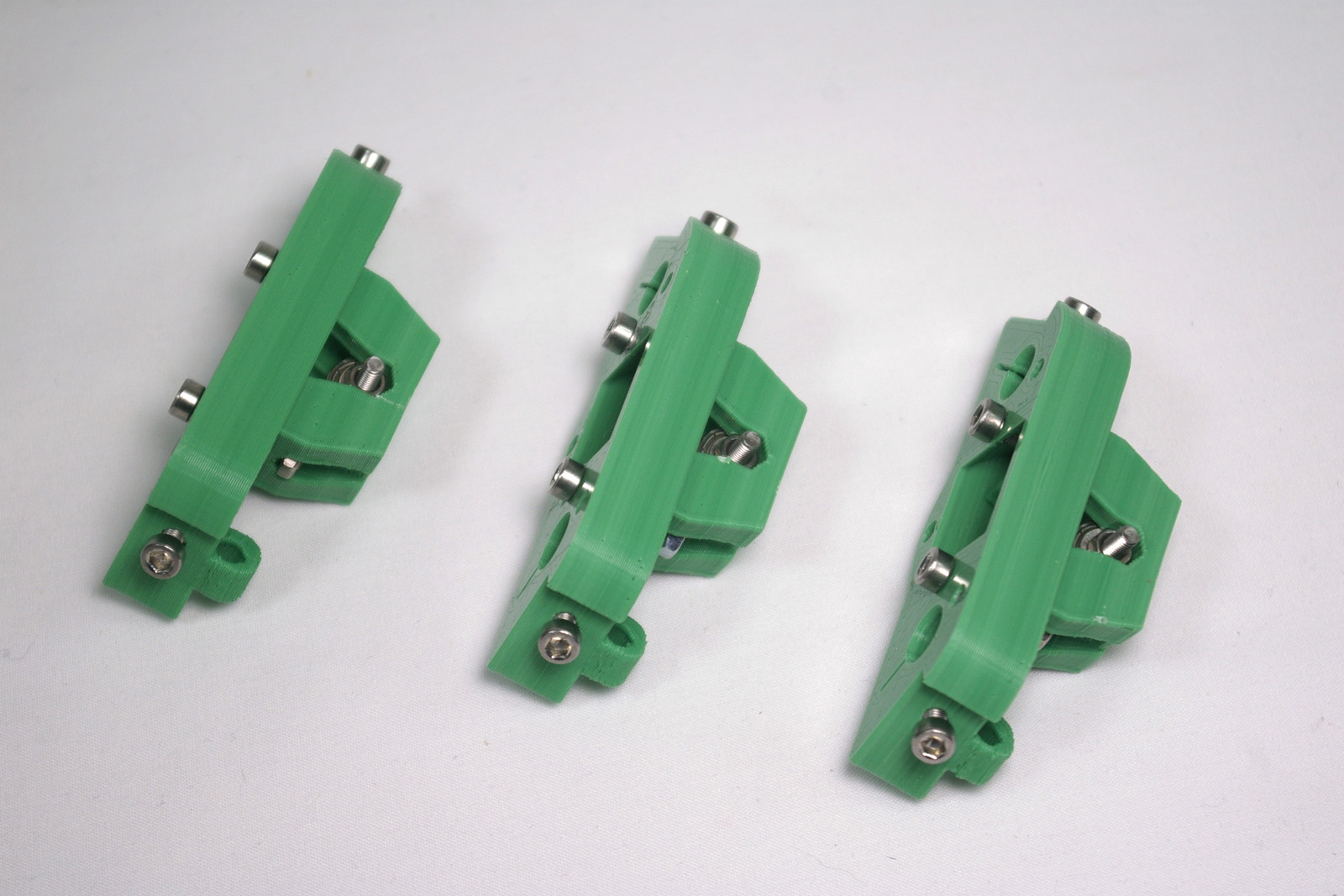 |
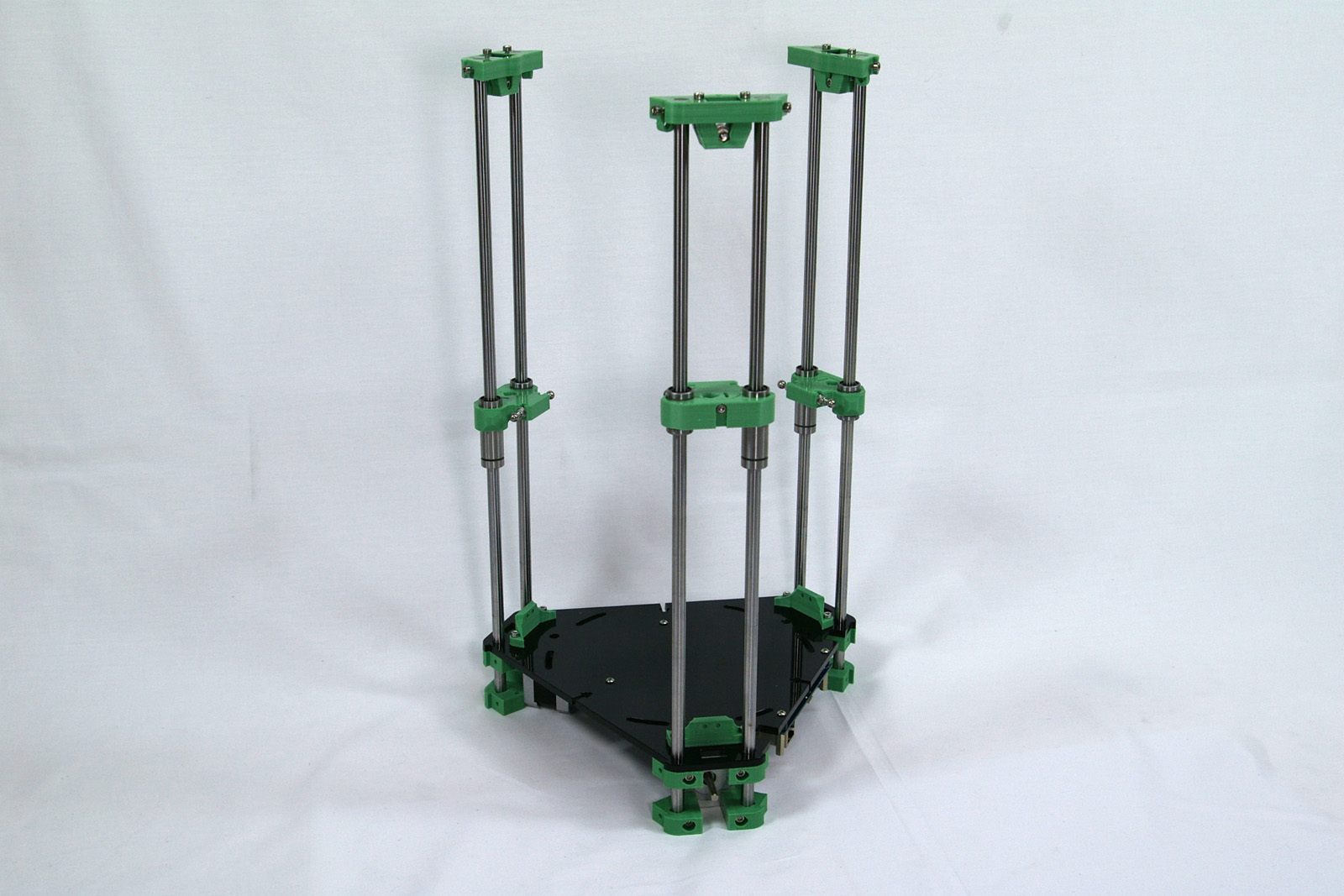
| Fit them, one on each tower, as shown. The smooth rod should be flush with the surface of the idler bracket. | 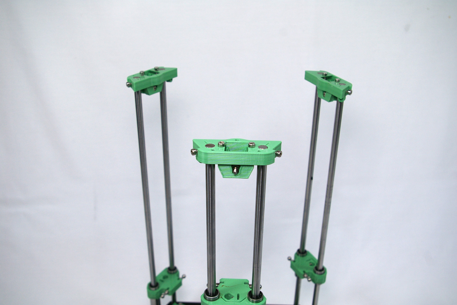 |
| The printer so far. |  |
Back – Base Assembly Next – Panels and Rods